Principles of Atoric Lens Design - Laramy-K Optical
Principles of Atoric Lens Design - Laramy-K Optical
Principles of Atoric Lens Design - Laramy-K Optical

Create successful ePaper yourself
Turn your PDF publications into a flip-book with our unique Google optimized e-Paper software.
<strong>Principles</strong> <strong>of</strong> <strong>Atoric</strong> <strong>Lens</strong> <strong>Design</strong><br />
Darryl Meister, ABOM<br />
<strong>Lens</strong> Talk<br />
SOLA Technical Marketing Vol. 27, No. 03 (Jan. 1998)<br />
BACKGROUND<br />
Industry studies have shown that approximately<br />
70% <strong>of</strong> all spectacle wearers receive a cylinder<br />
correction for astigmatism. Further, 50% <strong>of</strong> these<br />
wearers have corrections with over 0.50 D <strong>of</strong><br />
cylinder power. This article will show that<br />
conventional lens design does not adequately<br />
address the peripheral optical performance <strong>of</strong><br />
lenses with cylinder power. Moreover, it will<br />
explain how new ‘atoric’ lens designs can provide<br />
superior optical performance for all patients—<br />
including those with astigmatism.<br />
IN REVIEW<br />
Our discussion <strong>of</strong> ‘atoricity’ expands upon the<br />
principles and concepts that appeared in an earlier<br />
issue <strong>of</strong> <strong>Lens</strong> Talk (July 1998). Before continuing, we<br />
should review a few key points from this previous<br />
article:<br />
• Spectacle lenses suffer from various ‘lens<br />
aberrations’ that affect the quality <strong>of</strong> peripheral<br />
vision afforded by the lens. <strong>Optical</strong> performance<br />
can be improved by reducing these aberrations,<br />
or ‘optimizing’ the lens.<br />
• <strong>Lens</strong>es produced with optimum spherical front<br />
base curves are <strong>of</strong>ten referred to as ‘best form<br />
lenses,’ since these lenses reduce the lens<br />
aberrations that can blur peripheral vision.<br />
Today, most manufacturers provide best form<br />
lenses.<br />
• Early lenses employed spherical curves simply<br />
because these were relatively easy to produce in<br />
glass using simple tools. With the advent <strong>of</strong> highspeed<br />
computing, plastic lens casting, and<br />
numerically-controlled grinding techniques, lens<br />
manufacturers developed the ability to rapidly<br />
produce more sophisticated lens surfaces like<br />
aspherics.<br />
• Although steeper best form lenses provide<br />
excellent peripheral vision, they can be relatively<br />
thick, heavy, and bulbous. To answer the need<br />
for thinner, lighter, and flatter lenses that still<br />
maintained excellent optical performance,<br />
manufacturers began to use aspheric surfaces on<br />
spectacle lenses—<strong>of</strong>ten in conjunction with<br />
higher-index materials.<br />
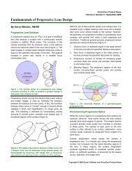
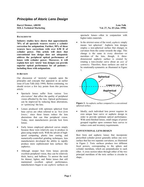
• In the strictest sense <strong>of</strong> the word, aspheric simply<br />
means ‘not spherical.’ Aspheric lens designs<br />
employ a non-spherical surface that changes in<br />
curvature from the center towards the edge. This<br />
change is the same in every direction—or<br />
meridian—<strong>of</strong> the lens, though. A threedimensional<br />
aspheric surface is created by<br />
rotating a non-circular curve about an axis <strong>of</strong><br />
symmetry. Therefore, these surfaces are said to<br />
be rotationally-symmetric as illustrated in Figure<br />
1.<br />
Spherical<br />
SYMMETRY AXIS<br />
Aspherical<br />
Figure 1. An aspheric surface compared to a conventional<br />
spherical surface.<br />
• Ideally, each individual lens power requires its<br />
own unique base curve or aspheric design in<br />
order to provide optimum optical performance.<br />
With semi-finished lenses, small ranges <strong>of</strong> power<br />
grouped together upon common base curves to<br />
reduce costs and inventory requirements.<br />
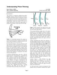
CONVENTIONAL LENS DESIGN<br />
Best form and aspheric lenses that incorporate<br />
prescribed cylinder power generally utilize one toric<br />
surface that has two separate curvatures, as illustrated<br />
in Figure 2. Toric surfaces produce two different<br />
focal powers, corresponding to the sphere and<br />
cylinder meridians, which are perpendicular to each<br />
other. A cross section taken through either <strong>of</strong> the two<br />
principal meridians <strong>of</strong> the toric surface is circular in<br />
shape.<br />
Page 1
Cylinder<br />
Meridian<br />
Curve<br />
Figure 2. Toric surface with circular cross sections.<br />
Sphere<br />
Meridian<br />
Curve<br />
Sphero-cylindrical lenses that use toric surfaces to<br />
produce cylinder power vary in power between the<br />
sphere and cylinder meridians <strong>of</strong> the lens, as shown in<br />
Figures 3 and 4. This is not the case with spherical<br />
lenses, which have a constant power around each<br />
meridian <strong>of</strong> the lens. Consider the comparison below:<br />
+2.00 D<br />
+2.00 D<br />
+2.00 D<br />
+2.00 D<br />
+2.00 D<br />
+2.00 D +2.00 D<br />
+2.00 D<br />
meridian, or the average power (spherical equivalent)<br />
<strong>of</strong> the lens. In lenses with low cylinder power the<br />
performance differences are generally negligible, but<br />
in higher cylinder powers the field <strong>of</strong> clear vision is<br />
<strong>of</strong>ten considerably reduced—no matter which<br />
approach is used. Best form and aspheric lenses with<br />
cylinder power could more accurately be described as<br />
a ‘best compromise’ lens.<br />
ATORIC LENS DESIGN<br />
Over the past few years, additional advances in lens<br />
design have provided lens designers with the ability<br />
to produce surfaces even more complex than the<br />
rotationally-symmetrical aspheric designs described<br />
earlier. By literally varying the amount <strong>of</strong> asphericity<br />
from one meridian <strong>of</strong> the lens to another, an atoric<br />
surface can be produced. Just as aspheric denotes a<br />
surface that departs from being completely spherical,<br />
‘atoric’ denotes a surface that departs from being an<br />
exact circular toric. Figure 5 depicts one possible<br />
atoric surface.<br />
Aspheric<br />
Sphere<br />
Curve<br />
+2.00 sph<br />
Figure 3. This +2.00 D spherical-powered lens has the<br />
same power through every raidal direction (or meridian) <strong>of</strong><br />
the lens.<br />
+2.00 D<br />
+1.50 D<br />
+1.00 D<br />
+1.50 D<br />
+1.00 D<br />
Aspheric<br />
Cylinder<br />
Curve<br />
+1.50 D +1.50 D<br />
+2.00 D<br />
+2.00 -1.00 × 090<br />
Figure 4. This sphero-cylindrical lens varies in power<br />
from meridian to meridian. The 90° meridian contains the<br />
sphere power <strong>of</strong> +2.00 D, and the 180° meridian contains<br />
the combined sphere and cylinder power: +2.00 + -1.00 =<br />
+1.00 D.<br />
Because each lens power requires its own lens form<br />
to eliminate aberrations, the design <strong>of</strong> lenses with<br />
sphere and cylinder powers cannot be entirely<br />
optimized using conventional spherical surfaces. The<br />
lens designer may choose the optimum front curve<br />
based upon the sphere meridian, the cylinder<br />
Figure 5. An atoric surface with a differing amount <strong>of</strong><br />
asphericity applied to the sphere and cylinder meridians.<br />
<strong>Atoric</strong>ity is an extension <strong>of</strong> aspheric design<br />
technology, allowing lens designers to optimize for<br />
both the sphere and cylinder powers <strong>of</strong> a lens. This<br />
ensures that nearly all wearers enjoy the same wide<br />
field <strong>of</strong> vision, especially those with astigmatism.<br />
<strong>Atoric</strong> lenses consistently outperform either best form<br />
(with spherical base curves) or rotationallysymmetrical<br />
aspheric lenses across a wide range <strong>of</strong><br />
prescriptions.<br />
The atoric lens provides a significantly wider field <strong>of</strong><br />
perfectly clear vision, and consistently provides<br />
optical performance superior to conventional lens<br />
designs over a wide range <strong>of</strong> lens powers—especially<br />
higher cylinder powers. Let’s look at the differences<br />
Page 2
etween best form, aspheric, and atoric optimization<br />
strategies using an actual prescription. Figure 6<br />
compares the ‘relative asphericity’ (an abstract<br />
correction concept used here for illustrative purposes)<br />
<strong>of</strong> three different lens designs for the following<br />
prescription: +2.00 -1.00 × 090.<br />
0.0<br />
-4.0<br />
-1.5<br />
0.0<br />
0.0<br />
Spherical Surface<br />
-4.0<br />
0.0<br />
0.0 0.0<br />
-4.0<br />
0.0<br />
Aspheric Surface<br />
-4.0<br />
-4.0<br />
-4.0 -4.0<br />
-2.5<br />
-4.0<br />
-2.5<br />
-2.5 -2.5<br />
-4.0<br />
0.0<br />
-4.0<br />
-1.5<br />
<strong>Atoric</strong> Surface<br />
Figure 6. Relative asphericity (or correction factors) for<br />
spherical, aspheric, and atoric surfaces.<br />
These values more or less represent the relative<br />
departure <strong>of</strong> the surface from a perfect circle through<br />
each meridian, and can be thought <strong>of</strong> as the amount <strong>of</strong><br />
asphericity present through that meridian. The further<br />
this value departs from 0.0, the more aspheric (or<br />
non-circular) the curvature <strong>of</strong> the surface is through<br />
that meridian. We can think <strong>of</strong> this relative value as<br />
the ‘correction factor’ for now (again, strictly for our<br />
purposes).<br />
Spherical surface. It has a relative value <strong>of</strong> 0.0 in<br />
every direction (or meridian)—meaning that it is<br />
perfectly spherical in every direction. Therefore, the<br />
+2.00 D sphere meridian receives the same correction<br />
factor <strong>of</strong> 0.0 as the +1.00 D cylinder meridian does.<br />
We know these two powers should be optimized<br />
differently, since a +1.00 D power requires a flatter<br />
base curve than a +2.00 D power.<br />
Aspheric surface. It has a relative value <strong>of</strong> -4.0,<br />
indicating the aspheric lens departs significantly from<br />
the spherical lens in every direction (or meridian).<br />
This is what is meant by the phrase ‘rotationallysymmetric’—the<br />
lens surface have the same curvature<br />
in every direction, and can be produced by simply<br />
rotating a single curve with the appropriate relative<br />
asphericity about an axis. Again, the aspheric lens<br />
provides only the one correction factor <strong>of</strong> -4.0<br />
through every meridian.<br />
<strong>Atoric</strong> surface. Note how the relative asphericity<br />
changes from meridian to meridian. The +2.00 D<br />
meridian has a correction factor <strong>of</strong> -4.0, while the<br />
+1.00 D meridian has a factor <strong>of</strong> -1.5. In essence,<br />
each meridian <strong>of</strong> the lens has been adjusted with the<br />
correction factor specifically required for that<br />
particular power. This ensures that both the sphere<br />
and cylinder meridional powers—as well as all <strong>of</strong> the<br />
powers in between—are properly optimized.<br />
Unfortunately, conventional spectacle lens surfacing<br />
equipment was not designed to manufacture these<br />
rather complex surfaces. For instance, modern<br />
cylinder machines and lap tools—which are used for<br />
fining and polishing the generated lens surface—can<br />
only produce spherical and circular toric surfaces<br />
because <strong>of</strong> the geometry and motions involved.<br />
Although there are systems available that use either a<br />
‘cut and coat’ process or a numerically-controlled<br />
milling machine along with flexible-pad polishing,<br />
these systems are quite expensive and cost-prohibitive<br />
for most laboratories at this point.<br />
Currently, most atoric lenses are available in either <strong>of</strong><br />
two forms: factory finished stock lenses—which have<br />
had the atoric surface molded at the factory, and<br />
custom-ground semi-finished lenses—which have had<br />
the atoric surface ground using the equipment<br />
described above (typically also at the factory level).<br />
The atoric design strategies that we’ve discussed so<br />
far are generally applicable to any single vision (or<br />
even multifocal) lens design. Certain manufacturers<br />
have begun <strong>of</strong>fering ‘atoric’ progressive addition<br />
lenses, but it should be noted that these atoric designs<br />
differ slightly from the design that we have looked at<br />
so far. These designs still optimize for both the sphere<br />
Page 3
and cylinder powers <strong>of</strong> the lens. In addition, however,<br />
these manufactures advertise that their lenses can also<br />
be optimized for other parameters, like aberrations<br />
produced by prism or by viewing through the near<br />
zone <strong>of</strong> the lens obliquely. This additional freedom is<br />
possible since each lens is custom ground (unlike<br />
finished, stock lenses). These surfaces are even more<br />
complex, or arbitrary, than the atoric surfaces used<br />
for stock lenses, and each lens has to be individually<br />
designed and fabricated using expensive equipment—<br />
usually at the factory level. Consequently, such lenses<br />
require additional shipping time and are considerably<br />
more expensive.<br />
Because <strong>of</strong> their obvious superiority to conventional<br />
lens designs over a wide range <strong>of</strong> prescriptions, we<br />
should expect to see more atoric single vision and<br />
progressive addition lenses in the future. We can now<br />
look at some optical performance comparisons<br />
between the three lens designs for plus and minus<br />
sphero-cylindrical prescriptions. All three <strong>of</strong> the lens<br />
designs shown in Figure 7 are from the same<br />
manufacturer. The white area within the frame<br />
represents the field <strong>of</strong> perfectly clear vision, while the<br />
shaded area represents the region <strong>of</strong> reduced optical<br />
quality and potential blur for the wearer.<br />
Field <strong>of</strong> Perfectly Clear Vision Comparison<br />
Best Form Poly Aspheric Poly <strong>Atoric</strong> Poly<br />
Rx:<br />
+4.00 –2.00<br />
Rx:<br />
-6.00 –2.00<br />
Figure 7. Comparison <strong>of</strong> the fields <strong>of</strong> perfectly clear vision for best form, aspheric, and atoric polycarbonate lens designs. Two<br />
prescriptions are shown. Note that the atoric lens design consistently provides a larger area <strong>of</strong> clear vision.<br />
Page 4