Methods for Estimating Lens Thickness - Laramy-K Optical
Methods for Estimating Lens Thickness - Laramy-K Optical
Methods for Estimating Lens Thickness - Laramy-K Optical

You also want an ePaper? Increase the reach of your titles
YUMPU automatically turns print PDFs into web optimized ePapers that Google loves.
<strong>Methods</strong> <strong>for</strong> <strong>Estimating</strong> <strong>Lens</strong> <strong>Thickness</strong><br />
Darryl Meister, ABOM<br />
<strong>Optical</strong> World<br />
SOLA Technical Marketing Vol. 26, No. 201 (Aug. 1997)<br />
BACKGROUND<br />
Often, it is beneficial <strong>for</strong> the eyecare professional<br />
to predict the finished thickness of a pair of<br />
spectacle lenses. Determining the change in<br />
thickness that results from the patient’s use of a<br />
different frame or lens style is a common example.<br />
Patients investing a considerable amount of money<br />
into thinner and lighter lenses want to know just<br />
how thin their new lenses will be. This is a<br />
question that often strikes fear in the hearts of<br />
unprepared opticians. Those armed with the<br />
knowledge required to provide the answer,<br />
however, quickly earn the respect of their<br />
patients. Even these opticians face a greater<br />
challenge today, since the advent of newer highindex<br />
lenses.<br />
REVIEWING SURFACE GEOMETRY<br />
The purpose of this article is to present the<br />
procedures and <strong>for</strong>mulas necessary to calculate the<br />
thickness of an ophthalmic lens. We will use<br />
relatively precise equations at first, and then go on to<br />
develop simpler expressions from these that can be<br />
utilized <strong>for</strong> estimating the approximate thickness. It<br />
will be shown that these simplified methods will<br />
provide reasonably accurate values <strong>for</strong> your patient,<br />
without the need <strong>for</strong> tedious, time-consuming<br />
mathematics.<br />
The first step towards determining the thickness of a<br />
given lens is developing an understanding of the<br />
relationship between surface power, diameter, and<br />
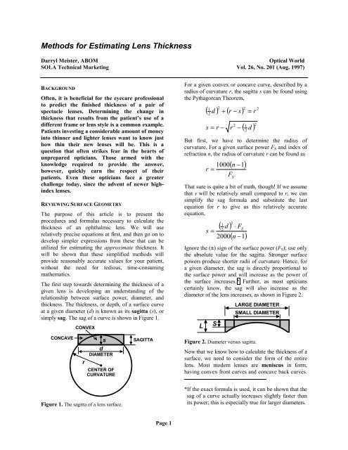
thickness. The thickness, or depth, of a surface curve<br />
at a given diameter (d) is known as its sagitta (s), or<br />
simply sag. The sag of a curve is shown in Figure 1.<br />
CONVEX<br />
For a given convex or concave curve, described by a<br />
radius of curvature r, the sagitta s can be found using<br />
the Pythagorean Theorem,<br />
( 1 2<br />
2<br />
d ) + ( r − s) 2<br />
= r<br />
2<br />
s = r −<br />
r<br />
2<br />
−<br />
1<br />
( d ) 2<br />
2<br />
But first, we have to determine the radius of<br />
curvature. For a given surface power F S and index of<br />
refraction n, the radius of curvature r can be found as<br />
( n )<br />
1000 −1<br />
r =<br />
F S<br />
That sure is quite a bit of math, though! If we assume<br />
that s will be relatively small compared to r, we can<br />
simplify the sag <strong>for</strong>mula and substitute the last<br />
equation <strong>for</strong> r to give us this relatively accurate<br />
equation,<br />
1 2<br />
( d ) ⋅ F<br />
2 S<br />
( n −1)<br />
s =<br />
2000<br />
Ignore the (±) sign of the surface power (F S ); use only<br />
the absolute value <strong>for</strong> the sagitta. Stronger surface<br />
powers produce shorter radii of curvature. Hence, <strong>for</strong><br />
a given diameter, the sag is directly proportional to<br />
the surface power and will increase as the power of<br />
the surface increases.* Further, as most opticians<br />
certainly know, the sag will also increase as the<br />
diameter of the lens increases, as shown in Figure 2.<br />
L<br />
S<br />
LARGE DIAMETER<br />
SMALL DIAMETER<br />
CONCAVE<br />
r<br />
s<br />
d<br />
DIAMETER<br />
•<br />
CENTER OF<br />
CURVATURE<br />
SAGITTA<br />
Figure 2. Diameter versus sagitta.<br />
Now that we know how to calculate the thickness of a<br />
surface, we need to consider the <strong>for</strong>m of the entire<br />
lens. Most modern lenses are meniscus in <strong>for</strong>m,<br />
having convex front curves and concave back curves.<br />
Figure 1. The sagitta of a lens surface.<br />
*If the exact <strong>for</strong>mula is used, it can be shown that the<br />
sag of a curve actually increases slightly faster than<br />
its power; this is especially true <strong>for</strong> larger diameters.<br />
Page 1
If the dioptric value of the front curve is greater than<br />
the value of the concave back curve, the lens will be<br />
positive (plus) in power. Similarly, if the dioptric<br />
value of the back curve is greater than the value of the<br />
convex front curve, the lens will be negative (minus)<br />
in power. Because these lenses have two surface<br />
curves, we need to consider the sag of both the front<br />
curve (s 1 ) and the back curve (s 2 ) <strong>for</strong> determining<br />
thickness.<br />
Generally, we are concerned with finding the<br />
maximum thickness of the lens. This will be the<br />
center thickness of plus lenses and the edge thickness<br />
of minus lenses. These lenses are often produced with<br />
a certain amount of minimum (or additional)<br />
thickness, as well. There<strong>for</strong>e, in addition to the<br />
thickness of each curve, we also need to add<br />
additional edge thickness <strong>for</strong> plus lenses (the thinnest<br />
point of the lens) and additional center thickness <strong>for</strong><br />
minus lenses (also the thinnest point of the lens).<br />
Figure 3 depicts the factors affecting the final center<br />
thickness of a meniscus plus lens.<br />
EDGE<br />
s CENTER<br />
1<br />
s 2<br />
Figure 3. A meniscus plus lens.<br />
To determine the final center thickness of a plus lens,<br />
use<br />
Center = s − s2<br />
1 +<br />
Edge<br />
To determine the final edge thickness of a minus lens,<br />
use<br />
Edge = s − s1<br />
2 +<br />
Center<br />
Yes, this is also a bit complex <strong>for</strong> a world demanding<br />
fast answers. When dealing with spectacle lenses of<br />
low-to-moderate power and reasonable diameter,<br />
however, we can further simplify the process by<br />
ignoring the surface curves and <strong>for</strong>m of the lens<br />
altogether! This is simply an extension of our earlier<br />
sagittal approximation, which says that the sag of a<br />
curve will be directly proportional to its power. So,<br />
how is this possible?<br />
This is possible because the surface powers of a lens<br />
(F 1 and F 2 ) must vary at the same rate to provide a<br />
given lens power F, so that*<br />
F = F 1 + F 2<br />
*This relationship holds true <strong>for</strong> thin lenses, and is in<br />
line with our approximation.<br />
As a consequence, the sags of each curve must also<br />
vary at the same rate. There<strong>for</strong>e, the difference<br />
between the sags will remain constant as the surface<br />
powers change. 1<br />
To visualize this concept, consider the <strong>for</strong>m of the<br />
lens as being flat, so that the lens power is produced<br />
by one surface curve with a single sagitta. The flat<br />
plus lens will have a convex front curve and a plano<br />
(flat) back curve, while the flat minus lens will have a<br />
plano front curve and a concave back curve. With the<br />
use of our approximation, the difference between the<br />
sags of the front and back curves will remain<br />
constant.<br />
At this point, we merely have to add the desired<br />
amount of minimum thickness to determine the final,<br />
maximum thickness of the lens. These simplified<br />
lenses are illustrated in Figures 4 and 5.<br />
SINGLE SAG<br />
EDGE<br />
Figure 4. A plano-convex plus lens.<br />
CENTER<br />
SINGLE SAG<br />
Figure 5. A plano-concave minus lens.<br />
We will now substitute the power of the lens (F)—<br />
ignoring the (±) sign—<strong>for</strong> the surface power (F S ) in<br />
our simplified sag <strong>for</strong>mula,<br />
s =<br />
2000<br />
1 2<br />
( d ) ⋅ F<br />
2<br />
( n −1)<br />
And, to determine the final maximum thickness of the<br />
lens, use the expression<br />
<strong>Thickness</strong> = s + Minimum<br />
And now a word about minimum center thicknesses...<br />
The manufacturer’s center thickness guidelines ensure<br />
that these lenses will have enough thickness to<br />
provide acceptable flexural stability and impact<br />
resistance.<br />
Most minus lenses will be either surfaced to or<br />
supplied in finished <strong>for</strong>m with centers between 1.0<br />
mm and 2.2 mm, depending upon the type of lens<br />
material and design. <strong>Lens</strong>es intended <strong>for</strong> rimless or<br />
safety frames, <strong>for</strong> instance, may be slightly thicker.<br />
To make things even easier, we can solve the<br />
equation <strong>for</strong> various values of the diameter d and the<br />
index n in advance. A table of such constants, which<br />
are called K-values, can be prepared and kept readily<br />
available. 2 From this point on, to approximate the<br />
Page 2
maximum thickness <strong>for</strong> a given index and diameter,<br />
we need to only multiply the appropriate K-value (K)<br />
by the power F of the lens. Remember to also add the<br />
minimum thickness. A sample table of K-values is<br />
provided later on in Table 1.<br />
<strong>Thickness</strong> = F × K + Minimum<br />
So far, so good—right? Up to this point, we have<br />
assumed two things: a lens power and a lens blank<br />
diameter. Obviously, the power should be known. If<br />
the diameter is unknown, a few more computations<br />
may be necessary. It is important to note that the<br />
center thickness of a finished plus lens is fixed with<br />
respect to the initial diameter of the lens blank. Once<br />
cast, plus lenses can only be surfaced to smaller<br />
diameters and thinner centers. When using finished<br />
plus lenses, the factory blank size should be utilized<br />
<strong>for</strong> determining the center thickness.<br />
The patient’s frame dimensions and interpupillary<br />
distance (distance PD) are required to determine the<br />
minimum blank size <strong>for</strong> a given pair of eyeglasses.<br />
The minimum blank size will be the smallest lens<br />
diameter required <strong>for</strong> a particular frame and lens<br />
combination. The dimensions of a typical spectacle<br />
frame, using the boxing system, are illustrated in<br />
Figure 6.<br />
A<br />
The effective diameter is twice the distance from the<br />
geometric center (GC) of the frame to the farthest<br />
point along the eyewire. The ED is essentially the<br />
minimum lens diameter that will completely<br />
encompass the frame, in the absence of decentration.<br />
If we know the patient’s interpupillary distance (PD),<br />
the eyesize (A) of the frame, and the width of the<br />
bridge (DBL), we can find the decentration (Dec)<br />
with<br />
A + DBL - PD<br />
DEC =<br />
2<br />
Combining both equations gives us<br />
MBS = ED + A + DBL - PD<br />
It should be apparent that this rule of thumb method<br />
does not consider the frame shape or the angle of the<br />
effective diameter. Determining the actual effective<br />
radius of the lens will be more accurate, when<br />
possible. Once the lens has been decentered, the<br />
effective radius will usually be located along the midline<br />
and toward the temporal edge of the frame. For<br />
harlequin, aviator, and similar styles with high or low<br />
temporal corners, the effective radius may be<br />
displaced up or down slightly, as shown in Figure 7.<br />
EFFECTIVE RADIUS<br />
B<br />
GC<br />
•<br />
• OC<br />
ED<br />
• OC<br />
OC<br />
•<br />
Figure 6. The Boxing System.<br />
Dec<br />
Once the optical center has been decentered from the<br />
geometric center, the minimum blank size (MBS)<br />
becomes equal to twice the effective radius (ER) of<br />
the decentered lens, which is the distance from the<br />
decentered optical center (OC) to the farthest point<br />
along the eyewire: MBS = 2 × ER.<br />
This distance can be estimated with a simple frame<br />
measurement. An easy rule of thumb to remember <strong>for</strong><br />
single vision lenses states that the minimum blank<br />
size MBS is approximately equal to the sum of the<br />
effective diameter ED of the frame and twice the<br />
required decentration (Dec), or<br />
MBS = ED + 2 × Dec<br />
Figure 7. Some exotic frame shapes.<br />
In general, myopic (nearsighted) patients are more<br />
likely to be concerned with the thickness of their<br />
lenses, since the edges of their minus lenses are quite<br />
visible to others. Let’s take a closer look at<br />
calculating the edge thickness of a minus lens.<br />
But first, we need to discuss lenses that require a<br />
cylinder component, since these lenses complicate<br />
matters somewhat. For simplicity, we are specifically<br />
concerned with the effective power of the lens<br />
through the horizontal (180°) meridian. The effective<br />
radius should be close to this meridian. For increased<br />
accuracy, you may choose to determine the effective<br />
power through the actual meridian of the effective<br />
radius. 3<br />
If the axis of the sphere power is close to 180°, the<br />
power of the lens through the horizontal meridian<br />
(F 180 ) is roughly equal to the sphere power S.<br />
Page 3
Table 1 K-values (Interpolate diameter values between the 5-mm increments)<br />
DIAMETER<br />
MATERIAL 40 45 50 55 60 65 70 75 80<br />
Hard Resin 0.40 0.51 0.63 0.76 0.90 1.06 1.23 1.41 1.60<br />
Crown Glass 0.38 0.48 0.60 0.72 0.86 1.01 1.17 1.34 1.53<br />
Spectralite ® 0.37 0.47 0.58 0.70 0.83 0.98 1.13 1.30 1.48<br />
Polycarbonate 0.34 0.43 0.53 0.65 0.77 0.90 1.05 1.20 1.37<br />
1.6 High-index 0.33 0.42 0.52 0.63 0.75 0.88 1.02 1.17 1.33<br />
1.66 High-index 0.30 0.38 0.47 0.57 0.68 0.80 0.93 1.07 1.21<br />
1.7 Glass 0.29 0.36 0.45 0.54 0.64 0.75 0.88 1.00 1.14<br />
If the axis is close to 90°, the power through the<br />
horizontal meridian (F 180 ) is roughly equal to the sum<br />
of the sphere and cylinder powers (S and C). For<br />
prescriptions with an oblique axis θ, between 90° and<br />
180°, the contribution of the cylinder power must be<br />
determined using the sine-squared rule,<br />
F<br />
2<br />
180 = S + C ⋅sin<br />
θ<br />
Now we can tell how much cylinder power C to add<br />
to the sphere power S <strong>for</strong> a given axis θ. It’s really <strong>for</strong><br />
those math buffs out there. For everyone else, get one<br />
of those handy cylinder distribution charts or learn<br />
the values <strong>for</strong> axes like 30° (25%), 45° (50%), 60°<br />
(75%), 90° (100%), 120° (75%), 135° (50%), and<br />
150° (25%).<br />
Keep in mind that, <strong>for</strong> a given diameter, the thinnest<br />
edge will be through the axis meridian of minus<br />
cylinder lenses, and the thickest edge will be through<br />
the power meridian. With these tools in mind, we can<br />
summarize the entire method <strong>for</strong> predicting the edge<br />
thickness of a minus lens.<br />
4 Steps <strong>for</strong> <strong>Estimating</strong> Edge <strong>Thickness</strong><br />
1. Determine the minimum blank size using the<br />
effective diameter, eyesize, bridge, and PD<br />
measurements (or the effective radius, if this is<br />
known).<br />
2. Determine the power of the lens through either<br />
the 180° meridian, or the effective radius<br />
meridian. Ignore the (±) sign.<br />
3. Determine the lens material (or the refractive<br />
index), and look up the nearest K-value from the<br />
table.<br />
4. Multiply the power by the K-value, and add the<br />
minimum thickness to this.<br />
This method, although simplified, will provide an<br />
acceptable degree of accuracy when precision is not<br />
critical. For higher plus and minus powers of rather<br />
large diameter, the exact <strong>for</strong>mulas described earlier<br />
should be employed. This is especially true <strong>for</strong> lens<br />
surfacing. The center thickness of sphero-cylindrical<br />
plus lenses may also be affected by the axis of the<br />
cylinder in some cases, but that discussion is beyond<br />
the scope of this paper. Otherwise, you can expect<br />
acceptable results <strong>for</strong> most situations.<br />
We will conclude the discussion with an example.<br />
Your patient, Nancy Cantsee, comes in with the<br />
following prescription:<br />
OU -3.00 DS -1.00 DC × 045<br />
PD 62 mm<br />
She selects a stylish round frame with a 52-mm<br />
eyesize, a 54-mm ED, and a 16-mm bridge. You are<br />
fitting her with SOLA’s Spectralite ® ASL finished<br />
aspheric lenses.<br />
1. The minimum blank size needed here is<br />
approximately equal to:<br />
MBS = ED + A + DBL - PD<br />
MBS = 54 + 52 +16 - 62<br />
MBS = 60 mm<br />
2. The effective power through the 180° meridian<br />
of these lenses is:<br />
F<br />
F<br />
2<br />
180 = S + C ⋅ sin θ<br />
180 = −3.00<br />
+ −<br />
180 = −3.50 D<br />
2<br />
( 1.00) sin 45<br />
F (Ignore ± sign.)<br />
3. You are using Spectralite ® , which has a K-value<br />
of 0.83 at a 60mm diameter.<br />
Page 4
4. The finished ASL lens has a 1-mm center<br />
thickness, which gives us a total of:<br />
<strong>Thickness</strong> = s + Minimum<br />
<strong>Thickness</strong> = 3.50( 0.83) + 1<br />
<strong>Thickness</strong> = 3.91mm<br />
The final answer: 3.91 mm. It is interesting to note<br />
that our estimation is within 0.15 mm of what the lens<br />
would actually produce! However, greater errors may<br />
be encountered depending upon the lens <strong>for</strong>m, power,<br />
and finished diameter.<br />
It should be kept in mind that the approximations<br />
described here are not entirely accurate <strong>for</strong> aspheric<br />
surfaces. For instance, the geometry of the ellipsoidal<br />
aspheric surface described in Figure 8 will af<strong>for</strong>d a<br />
slightly smaller sag value than a comparable spherical<br />
surface of the same diameter. Consequently, the<br />
sagitta calculations previously described should only<br />
be used <strong>for</strong> an estimation of thickness.<br />
Sag<br />
Difference<br />
Spherical<br />
Aspherical<br />
Figure 8. The difference in sag values between a spherical<br />
and a comparable aspheric surface.<br />
<strong>Thickness</strong> is obviously a very important aspect of<br />
ophthalmic lenses. However, consideration should<br />
also be given to other factors that contribute to the<br />
overall cosmesis of a pair of eyeglasses. For instance,<br />
materials with lower densities will be lighter in<br />
weight, and flatter base curves will reduce the<br />
bulbous appearance of the lenses. Although a<br />
discussion of these factors would be out of the scope<br />
of this article, they should certainly be given equal<br />
attention when fitting eyewear.<br />
REFERENCES<br />
1. Jalie, M. Principles of Ophthalmic <strong>Lens</strong>es, 4 th<br />
Ed. London: Association of British Dispensing<br />
Opticians, 1994. Page 54<br />
2. Brooks, C. Understanding <strong>Lens</strong> Surfacing.<br />
Stoneham: Butterworth-Heinemann, 1992. Page<br />
124<br />
3. Chase, G. Decentration and Minus <strong>Lens</strong><br />
<strong>Thickness</strong>. Washington, D.C.: <strong>Optical</strong><br />
Laboratories Association, 1977. Page 2<br />
Page 5