OpenOptix ABO Study Guide - Laramy-K Optical
OpenOptix ABO Study Guide - Laramy-K Optical
OpenOptix ABO Study Guide - Laramy-K Optical

Create successful ePaper yourself
Turn your PDF publications into a flip-book with our unique Google optimized e-Paper software.
<strong>OpenOptix</strong><br />
<strong>ABO</strong> <strong>Study</strong> <strong>Guide</strong><br />
Ver. 1.3<br />
This document is licensed under the Creative Commons Attribution 3.0 License. 7/30/2009<br />
1
About This Document<br />
The <strong>OpenOptix</strong> <strong>ABO</strong> <strong>Study</strong> <strong>Guide</strong>, sponsored by <strong>Laramy</strong>-K <strong>Optical</strong> and<br />
OpticianWorks.com, has been written and is maintained by volunteer members of the<br />
optical community. This document is completely free to use, share, and distribute. For the<br />
latest version please, visit www.openoptix.org or www.laramyk.com. The quality, value,<br />
and success of this document are dependent upon your participation. If you benefit from<br />
this document, we only ask that you consider doing one or both of the following:<br />
1. Make an effort to share this document with others whom you believe may benefit<br />
from its content.<br />
2. Make a knowledge contribution to improve the quality of this document.<br />
Examples of knowledge contributions include original (non-copyrighted) written<br />
chapters, sections, corrections, clarifications, images, photographs, diagrams, or<br />
simple suggestions.<br />
With your help, this document will only continue to improve over time.<br />
The <strong>OpenOptix</strong> <strong>ABO</strong> <strong>Study</strong> <strong>Guide</strong> is the pilot project of the <strong>OpenOptix</strong> initiative. Taking<br />
a cue from the MIT OpenCourseWare initiative and similar programs from other<br />
educational institutions, <strong>OpenOptix</strong> is an initiative to encourage, develop, and host free<br />
and open optical education to improve optical care worldwide.<br />
By providing free and open access to optical education the goals of the <strong>OpenOptix</strong><br />
initiative are to:<br />
• Improve optical care worldwide by providing free and open access to optical<br />
training materials, particularly for parts of the world where training materials and<br />
trained professionals may be limited.<br />
• Provide opportunities for optical professionals of all skill levels to review and<br />
improve their knowledge, allowing them to better serve their customers and<br />
patients<br />
• Provide staff training material for managers and practitioners<br />
• Encourage <strong>ABO</strong> certification and advanced education for opticians in the U.S.<br />
• Inspire innovation, creativity, and collaboration in the optical professions.<br />
For more information about <strong>OpenOptix</strong> visit www.laramyk.com, www.openoptix.org, or<br />
contact Keith Benjamin at keith@laramyk.com<br />
This document is licensed under the Creative Commons Attribution 3.0 License. 7/30/2009<br />
2
DOCUMENT SPONSORS AND CONTRIBUTING AUTHORS<br />
<strong>Laramy</strong>-K <strong>Optical</strong><br />
800.525.1274<br />
www.laramyk.com<br />
John Seegers, <strong>ABO</strong>C<br />
www.opticianworks.com<br />
Harry Chilinguerian <strong>ABO</strong>-AC, NCLE-AC<br />
www.technicalopticians.org<br />
Gary McArrell, <strong>ABO</strong>M<br />
George Karber, <strong>ABO</strong>C<br />
Bob Faktor, <strong>ABO</strong>C<br />
Bob Fesmire, <strong>ABO</strong>C<br />
Carrie Wilson, <strong>ABO</strong>-AC, NCLEC<br />
William MacGillivray<br />
Keith Benjamin<br />
This document is licensed under the Creative Commons Attribution 3.0 License. 7/30/2009<br />
3
DOCUMENT SPONSORS AND CONTRIBUTING AUTHORS ............................3<br />
CHAPTER 1: OCCULAR ANATOMY ..................................................................6<br />
Major Ocular Structures ............................................................................................................................. 6<br />
Refractive Errors.......................................................................................................................................... 8<br />
Extraocular Muscles................................................................................................................................... 11<br />
CHAPTER 2: BASIC OPTICAL PRINCIPLES ...................................................13<br />
Light and the Electromagnetic Spectrum................................................................................................. 13<br />
Index of Refraction..................................................................................................................................... 14<br />
Lens Power.................................................................................................................................................. 16<br />
Prism............................................................................................................................................................ 16<br />
Prism by Decentration ............................................................................................................................... 18<br />
CHAPTER 3: LENS FORM ................................................................................19<br />
Sphere.......................................................................................................................................................... 19<br />
Cylinder....................................................................................................................................................... 22<br />
Aspheric Lenses .......................................................................................................................................... 26<br />
Transposing Prescriptions ......................................................................................................................... 29<br />
CHAPTER 4: LENS OPTIONS...........................................................................30<br />
Lens Materials ............................................................................................................................................ 30<br />
Lens Material Properties Summary.......................................................................................................... 34<br />
Principles of AR Coatings.......................................................................................................................... 35<br />
Photochromic Lenses.................................................................................................................................. 36<br />
Polarized Lenses ......................................................................................................................................... 37<br />
This document is licensed under the Creative Commons Attribution 3.0 License. 7/30/2009<br />
4
Scratch, UV, and Mirror Coatings............................................................................................................ 39<br />
Multifocal Lenses........................................................................................................................................ 40<br />
Progressive Addition Lenses...................................................................................................................... 43<br />
Occupational Lenses................................................................................................................................... 49<br />
Slab Offs...................................................................................................................................................... 51<br />
Cataract Lenses .......................................................................................................................................... 53<br />
CHAPTER 5: FRAMES ......................................................................................55<br />
The Boxing System ..................................................................................................................................... 55<br />
Frame Styles and Materials....................................................................................................................... 57<br />
Frame Selection .......................................................................................................................................... 66<br />
Fitting and Adjustment.............................................................................................................................. 76<br />
CHAPTER 6: TOOLS .........................................................................................84<br />
Lensometer.................................................................................................................................................. 84<br />
Hand Tools and Instruments..................................................................................................................... 89<br />
CHAPTER 7: REGULATIONS AND STANDARDS ...........................................94<br />
Regulatory Agencies................................................................................................................................... 94<br />
Standards Publications of Interest to Opticians ...................................................................................... 94<br />
Impact Resistance Testing ......................................................................................................................... 98<br />
Liability and Duty to Warn ....................................................................................................................... 98<br />
DOCUMENT LICENSE.......................................................................................99<br />
This document is licensed under the Creative Commons Attribution 3.0 License. 7/30/2009<br />
5
Chapter 1: OCCULAR ANATOMY<br />
Major Ocular Structures<br />
The eye is made up of three layers: the outer layer called the fibrous tunic, which<br />
consists of the sclera and the cornea; the middle layer responsible for nourishment,<br />
called the vascular tunic, which consists of the iris, the choroid, and the ciliary body;<br />
and the inner layer of photoreceptors and neurons called the nervous tunic, which<br />
consists of the retina.<br />
The eye also contains three fluid-filled chambers. The volume between the cornea and the<br />
iris is known as the anterior chamber, while the volume between the iris and the lens is<br />
know as the posterior chamber, both chambers contain a fluid called aqueous humor.<br />
Aqueous humor is watery fluid produced by the ciliary body. It maintains pressure<br />
(called intraocular pressure or IOP) and provides nutrients to the lens and cornea.<br />
Aqueous humor is continually drained from the eye through the Canal of Schlemm. The<br />
greatest volume, forming about four-fifths of the eye, is found between the retina and the<br />
lens called the vitreous chamber. The vitreous chamber is filled with a thicker gel-like<br />
substance called vitreous humor which maintains the shape of the eye.<br />
Light enters the eye through the transparent, dome shaped cornea. The cornea consists of<br />
five distinct layers. The outermost layer is called the epithelium which rests on<br />
Bowman's Membrane. The epithelium has the ability to quickly regenerate while<br />
Bowman's Membrane provides a tough, difficult to penetrate barrier. Together the<br />
This document is licensed under the Creative Commons Attribution 3.0 License. 7/30/2009<br />
6
epithelium and Bowman’s Membrane serve to protect the cornea from injury. The<br />
innermost layer of the cornea is called the endothelium which rests on Descemet's<br />
Membrane. The endothelium removes water from cornea, helping to keep the cornea<br />
clear. The middle layer of the cornea, between the two membranes is called the stroma<br />
and makes up 90% of the thickness of the cornea.<br />
From the cornea, light passes through the pupil. The amount of light allowed through the<br />
pupil is controlled by the iris, the colored part of the eye. The iris has two muscles: the<br />
dilator muscle and the sphincter muscle. The dilator muscle opens the pupil allowing<br />
more light into the eye and the sphincter muscle closes the pupil, restricting light into the<br />
eye. The iris has the ability to change the pupil size from 2 millimeters to 8 millimeters.<br />
Just behind the pupil is the crystalline lens. The purpose of the lens is to focus light on<br />
the retina. The process of focusing on objects based on their distance is called<br />
accommodation. The closer an object is to the eye, the more power is required of the<br />
crystalline lens to focus the image on the retina. The lens achieves accommodation with<br />
the help of the ciliary body which surrounds the lens. The ciliary body is attached to lens<br />
via fibrous strands called zonules. When the ciliary body contracts, the zonules relax<br />
allowing the lens to thicken, adding power, allowing the eye to focus up close. When<br />
ciliary body relaxes, the zonules contract, drawing the lens outward, making the lens<br />
thinner, and allowing the eye to focus at distance.<br />
This document is licensed under the Creative Commons Attribution 3.0 License. 7/30/2009<br />
7
Light reaches its final destination at the retina. The retina consists of photoreceptor cells<br />
called rods and cones. Rods are highly sensitive to light and are more numerous than<br />
cones. There are approximately 120 million rods contained within the retina, mostly at<br />
the periphery. Not adept at color distinction, rods are suited to night vision and peripheral<br />
vision. Cones, on the other hand, have the primary function of detail and color detection.<br />
There are only about 6 million cones contained with in the retina, largely concentrated in<br />
the center of the retina called the fovea. There are three types of cones. Each type<br />
receives only a narrow band of light corresponding largely to a single color: red, green, or<br />
blue. The signals received by the cones are sent via the optic nerve to the brain where<br />
they are interpreted as color. People who are color blind are either missing or deficient in<br />
one of these types of cones.<br />
Refractive Errors<br />
Refractive errors occur when abnormalities of the eye prevent the proper focus of light on<br />
the retina. Emmetropia refers to an eye free of refractive errors.<br />
Two common types of refractive errors are myopia and hyperopia.<br />
This document is licensed under the Creative Commons Attribution 3.0 License. 7/30/2009<br />
8
Myopia<br />
Myopia, also known as near-sightedness, occurs if the eye is longer than normal or the<br />
curve of the cornea is too steep, causing light rays focus in front of the retina. Patients<br />
with myopia are able to see objects at near, but distant objects appear blurred. Clear<br />
vision can be restored to most myopes through the use of minus-powered lenses.<br />
This document is licensed under the Creative Commons Attribution 3.0 License. 7/30/2009<br />
9
Hyperopia<br />
Hyperopia, also known as far-sightedness, occurs if the eye is too short or the curve of<br />
the cornea is too flat, causing light rays to focus behind the retina. Patients with<br />
hyperopia are able to see objects at distance, but near objects appear blurred. Mildly<br />
hyperopic patients may be able to see clearly at near without correction by using<br />
accommodation to compensate. Clear vision can be restored to most hyperopes through<br />
the use of plus-powered lenses.<br />
Astigmatism<br />
An even more common type of refractive error is astigmatism. Astigmatism occurs when<br />
the cornea has an oblong, football-like shape in one or more directions (or axes) causing<br />
light rays to focus on more than one point on the retina. Astigmatism is compensated for<br />
using cylinder powered lenses along the appropriate axis.<br />
Presbyopia<br />
As eyes age, the crystalline lens begins to lose elasticity. With the loss of elasticity, the<br />
eye loses the ability to accommodate or focus at near. This typically becomes noticeable<br />
around 40 years of age. This condition where the crystalline lens is unable to add<br />
sufficient power to focus at near is known as presbyopia. The loss of elasticity in the<br />
crystalline lens continues until somewhere around the age of 65 when all the elasticity is<br />
gone from the lens as is all ability to accommodate. Presbyopia can be compensated for<br />
through the use of plus-powered lens segments, reading glasses, or magnifying devices.<br />
This document is licensed under the Creative Commons Attribution 3.0 License. 7/30/2009<br />
10
Anisometropia is a condition in which the two eyes have unequal refractive power.<br />
Antimetropia is an extreme case of anisometropia where one eye is myopic and the other<br />
is hyperopic. The unequal refractive states can often lead to diplopia (double vision) or<br />
asthenopia (eye strain).<br />
Anisometropia can adversely affect the development of binocular vision in infants and<br />
children, if there is a large difference between the two eyes. The brain will often suppress<br />
the vision of the blurrier eye in a condition called amblyopia, or lazy eye (a condition<br />
often mistakenly confused with phorias and tropias discussed later in this section).<br />
Extraocular Muscles<br />
The stabilization of eye movement is accomplished by six extraocular muscles attached<br />
to the eye via the sclera. The six muscles and their function are:<br />
Lateral rectus - moves the eye outward, away from the nose<br />
Medial rectus - moves the eye inward, toward the nose<br />
Superior rectus - moves the eye upward and slightly outward<br />
Inferior rectus - moves the eye downward and slightly inward<br />
Superior oblique - moves the eye outward and downward<br />
Inferior oblique - moves the eye outward and upward<br />
This document is licensed under the Creative Commons Attribution 3.0 License. 7/30/2009<br />
11
In addition to movement and tracking, extraocular muscles maintain alignment between<br />
the eyes. When the eyes are properly aligned, the brain is able to fuse the disparate<br />
images received by each eye into a single image. If any of the extraocular muscles are<br />
stronger or weaker than they should be, eye alignment can be affected making fusion<br />
difficult or impossible. Difficulty with fusion can cause double vision, also known as<br />
diplopia, or can cause the brain to "turn off" one image in an effort to eliminate diplopia.<br />
The latter is a condition known as suppression.<br />
When the eye has a tendency to turn from its normal position (such as when the patient is<br />
tired), it is called a phoria. When the eye has a definite or obvious turning from its<br />
normal position, it is called a tropia. Phorias and tropias are further described by the<br />
direction of the turning: exo meaning outward or in a temporal direction (e.g. exotropia);<br />
eso meaning inward or in a nasal direction (e.g. esotropia); hyper meaning upward (e.g.<br />
hyperphoria); and hypo meaning downward (e.g. hypophoria).<br />
This document is licensed under the Creative Commons Attribution 3.0 License. 7/30/2009<br />
12
Chapter 2: BASIC OPTICAL PRINCIPLES<br />
Light and the Electromagnetic Spectrum<br />
Produced by the nuclear cauldrons of stars and all matter in the cosmos, energy in the<br />
form of electromagnetic radiation permeates our entire universe. Every second of every<br />
day we are bombarded with and surrounded by electromagnetic radiation; some bounces<br />
off of our bodies, some passes through us, and some we absorb, but most goes undetected<br />
and unperceived.<br />
Electromagnetic energy travels at the speed of light (approx. 2.9x10^8 m/s or 186,000<br />
miles/sec) in the form of a wave. In fact, we classify electromagnetic energy according to<br />
its wavelength. Wavelength is defined as the distance between two corresponding points<br />
on two consecutive waves. Electromagnetic wavelengths range in scale from that of an<br />
atomic nucleus (gamma rays) to that of a small planet (radio waves).<br />
A tiny fraction of electromagnetic radiation is visible to the human eye. Only the portion<br />
of the electromagnetic spectrum that makes it through our corneas and is absorbed by our<br />
retinas is perceived as color and light. Often expressed in nanometers (nm) or one<br />
billionth of a meter, the wavelengths of the visible spectrum lie between 400 and 700nm,<br />
with red light at the longer end of the spectrum and violet light at the shorter end. A<br />
common acronym used to remember the order of colors in the visible spectrum is ROY G<br />
BIV (red, orange, yellow, green, blue, indigo, and violet). Just below the visible spectrum<br />
from 1 to 400nm lies ultraviolet (UV), while just above from 750nm to 1mm lies infrared<br />
(IR).<br />
This document is licensed under the Creative Commons Attribution 3.0 License. 7/30/2009<br />
13
Figure 1: Electromagnetic Spectrum – Image source: Wikipedia<br />
Index of Refraction<br />
Light waves travel through transparent media at different speeds. As light moves from<br />
one transparent medium to another, at any angle other than perpendicular to the material<br />
surface, the change in speed will also result in a change in direction. This change is<br />
direction is called refraction. The greater the change in speed, the greater the magnitude<br />
of refraction becomes. Refraction is principle that allows the creation of optical lenses<br />
that alter the path or focus of light.<br />
This document is licensed under the Creative Commons Attribution 3.0 License. 7/30/2009<br />
14
The straw seems to be broken, due to refraction of light as it emerges into the air. Image source:<br />
Wikipedia<br />
The index of refraction is a measure of how much the speed of light is altered as enters a<br />
given media relative to the speed of light in air. The index of refraction (n) can be<br />
calculated using the following equation:<br />
n = speed of light in air / speed of light in selected material<br />
The following are examples of n in various media:<br />
Air: 1.00<br />
Aqueous Humor: 1.33<br />
Vitreous Humor: 1.33<br />
Cornea: 1.37<br />
Crystalline Lens: 1.42<br />
CR-39 Plastic: 1.49<br />
Crown Glass: 1.52<br />
Polycarbonate: 1.58<br />
High Index Plastics: 1.60 to 1.74<br />
High Index Glass: 1.60 to 1.80<br />
This document is licensed under the Creative Commons Attribution 3.0 License. 7/30/2009<br />
15
Lens Power<br />
As light rays pass through a lens with power, the rays are bent or refracted. In a lens with<br />
a plus power, the light rays converge or are refracted toward one another. The point at<br />
which the light rays converge is called the focal point and in a plus lens, is behind the<br />
lens surface. In a lens with a minus power, the light rays diverge or are refracted away<br />
from one another. If these rays are extrapolated or traced back toward the light source,<br />
the lines will converge and form a focal point in front of the lens surface.<br />
The lens power is relative to the focal distance or the distance between the focal point and<br />
the lens. More specifically, lens power is the reciprocal of the focal distance in meters.<br />
Lens power is expressed in diopters (D).<br />
Power = 1 / Focal Distance<br />
As explained above, if the light rays converge, the focal distance is expressed with a<br />
positive value resulting in a positive or plus power. If the light rays diverge, the focal<br />
distance is expressed with a negative value resulting in a negative or minus power.<br />
Example:<br />
Light rays pass through a lens and converge 0.50 m from the lens. What is the power of<br />
the lens?<br />
Power = 1 / Focal Distance<br />
Power = 1 / 0.50 m<br />
Power = 2.00 D<br />
Prism<br />
Prism can be used to correct vision for an individual whose eyes are not perfectly aligned<br />
as with, for example, a patient with strabismus. When the eyes are not aligned, the right<br />
and left eye see different images resulting in blurred or double vision. Sometimes the<br />
brain can even "shut off" one eye, in an attempt to remedy the vision, resulting in<br />
monocular vision and loss of depth perception. Prism can sometimes be used to align the<br />
This document is licensed under the Creative Commons Attribution 3.0 License. 7/30/2009<br />
16
images seen by both eyes, so the eyes can fuse or see the same image, restoring visual<br />
clarity and depth perception.<br />
Prism, like lens power, is also measured in diopters (Δ), but measured differently. One<br />
diopter of prism is equal to the prism required to divert a ray of light 1 cm from its<br />
original path, measured at a distance of 1 m from the prism.<br />
As important as the amount of prism, is the direction of prism. The prism must displace<br />
viewed objects in the proper direction to achieve the desired visual correction. Prism<br />
direction can be specified in two ways, either using the prescriber's method or the 360°<br />
method.<br />
The prescriber's method specifies the direction if the prism in terms of the base, using<br />
base-up, base-down, base-in, and base-out (base-in referring to the direction of the nose<br />
and base-out referring to the direction of the temple). Often prescriptions will include a<br />
combination of directions to achieve the proper resultant prism. For example: 2 Δ base-in<br />
and 1 Δ base-up.<br />
Labs however, use a 360° or 180° method of describing base direction. Using the 360°<br />
method, when a lens is viewed from the front, a prism with a base direction to the right<br />
(base-in for the right eye and base-out for the left) becomes 0°. Likewise, a prism with a<br />
base direction to the left (base-out for the right eye and base-in for the left) becomes<br />
180°. Base-up then becomes 90° and base-down 270°. Using this method, prism<br />
directions other than base-in, base-out, base-up, and base-down can be specified at a<br />
single angle e.g. 2.7 Δ base 64°. The 180° method is similar, however, as the name<br />
suggests, only 180° are used, consequently, an up or down direction must also be<br />
specicfied.<br />
Prism specified in using the presciber's method consisting of multiple base direction<br />
components can easily be converted to the 360° or 180° methods by using a prism chart<br />
or simple trigonometric formulae.<br />
360° resultant prism can be calculated with the following equation:<br />
R = Sqrt( V^2 + H^2 )<br />
Where V is the vertical prism and H is horizontal prism.<br />
The resultant angle can be calculated using this equation:<br />
Tan(Δ) = V/H<br />
This document is licensed under the Creative Commons Attribution 3.0 License. 7/30/2009<br />
17
Prism by Decentration<br />
To better understand why there is induced prism, the cross-section of a plus lens can be<br />
likened to two prisms base-to-base, as the lens is thicker in the middle and thinner at the<br />
edges. Likewise, a minus lens can be likened to two prisms apex-to-apex, thinner in the<br />
middle and thicker at the edges.<br />
This induced prism can actually be used to the advantage of the lab when prism is called<br />
for in a prescription. If the lens power is sufficient, to induce the prescribed prism, the<br />
lens can simply be cut off-center to achieve the required results. This is known as prism<br />
by decentration. If the power is insufficient, however, the prism must be cut into the<br />
surface of the lens.<br />
A simple equation can be used to calculate the prism induced by decentration. Prentice’s<br />
rule states that prism in diopters (Δ) is equal to the decentration distance (c) in<br />
centimeters multiplied by the lens power (D).<br />
Prentice’s Rule<br />
Δ = cD<br />
This document is licensed under the Creative Commons Attribution 3.0 License. 7/30/2009<br />
18
Chapter 3: LENS FORM<br />
Sphere<br />
It can be helpful to think of very basic lens forms in terms of prisms. Recall, as light<br />
passes through a prism it is refracted toward the prism base. Minus lenses therefore<br />
resemble two prisms apex to apex spreading light rays outward as they pass through the<br />
lens, while plus lenses resemble two prisms base to base converging light rays as they<br />
pass through the lens.<br />
This document is licensed under the Creative Commons Attribution 3.0 License. 7/30/2009<br />
19
Of course, most lenses are not comprised of angular prismatic surfaces but consist of<br />
curved surfaces. The most basic of these curves is a sphere. The curve on the surface of a<br />
spherical lens, if extrapolated in all directions, would form a ball or perfect sphere. The<br />
sphere would vary in size based on the steepness of the curve. A steeper, higher power<br />
curve would form a smaller sphere with a smaller radius, while a flatter, lower power<br />
curve would form a larger sphere with a larger radius.<br />
In addition to being described by their power or radius, spherical curves also have a<br />
direction. An inward curve is called concave, while an outward curve is called convex.<br />
Thinking back to the prism example, a minus lens that diverges light would require a<br />
concave spherical surface, while a plus lens that converges light would require a convex<br />
surface. Therefore, we use the minus (-) sign to denote concave curves, the plus (+) sign<br />
to denote convex curves, and the term "plano" to describe a flat or zero curve.<br />
A lens has two curved surfaces of consequence to the vision of the wearer: the front<br />
surface and the back surface. Common lens shapes based on front and back curves are<br />
described in the figure below.<br />
This document is licensed under the Creative Commons Attribution 3.0 License. 7/30/2009<br />
20
The corrective power of a lens is determined by adding the front curve to the back curve.<br />
This is expressed by the equation: F 1 + F 2 = F Total . As you can see from this equation for<br />
any given corrective power, an infinite number of curve combinations may be used to<br />
achieve the same result.<br />
Example:<br />
+6.00 D + -2.00 D = +4.00 D<br />
+4.00 D + 0.00 D (plano) = +4.00 D<br />
+2.00 D + +2.00 D = +4.00 D<br />
Practically speaking, the laboratory has a limited number of curve combinations with<br />
which to work. Lens blanks come from manufacturers with a limited selection of front<br />
curves, also known as base curves, with suggested power ranges for each. Furthermore,<br />
since aberrations occur as the eye moves away from the optical center of the lens, the lab<br />
will choose curves that minimize aberrations. Lenses with curves chosen to minimize<br />
aberrations are called "corrected curve" or "best form" lenses.<br />
This document is licensed under the Creative Commons Attribution 3.0 License. 7/30/2009<br />
21
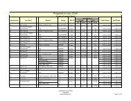
The following chart shows basic guidelines for selecting base curves to minimize<br />
peripheral aberrations.<br />
Sphere Power Base Curve<br />
> +12.25 +16.00 D<br />
+10.75 to +12.25 +14.00 D<br />
+9.00 to +10.50 +12.00 D<br />
+5.50 to +8.75 +10.00 D<br />
+2.25 to +5.25 +8.00 D<br />
-1.75 to +2.00 +6.00 D<br />
-2.00 to -4.50 +4.00 D<br />
-4.75 to -8.00 +2.00 D<br />
-8.00 to -9.00 +0.50 D<br />
< -9.00 plano or minus<br />
Remember, these are only guidelines for selecting base curves, there are typically many<br />
more factors involved in base curve selection including: manufacturer recommendations,<br />
frame selection, aesthetics, lens material, and patient history.<br />
Cylinder<br />
In addition to the spherical curve, many prescriptions call for a cylinder curve to correct<br />
for astigmatism. A cylinder curve is curved along a single axis and flat along the<br />
perpendicular axis. Furthermore, while the focus of a spherical curve is a single point, the<br />
focus of a cylinder curve is a line. The meridian along which there is no cylinder power<br />
in the lens and consequently the meridian of the cylindrical focus is the cylinder axis. The<br />
cylinder axis is expressed in degrees between 0 and 180.<br />
This document is licensed under the Creative Co mmons Attribution 3.0 License. 7/30/2009<br />
22
Most prescriptions have some combination of spherical and cylinder curves. A lens that<br />
combines spherical and cylinder curves is called a compound lens or toric. The<br />
convention of the power cross helps conceptualize the compound lens. The power cross is<br />
a representation of the two major meridians of the lens surface. The simplest combination<br />
to visualize is a plano with +4.00 D cylinder. The above examples show the cylinder<br />
curve at right angles. Note how the power in the meridian of the cylinder axis is plano,<br />
while the power of the meridian perpendicular to the cylinder axis is +4.00 D. To fully<br />
understand the cylinder curve, however, it is important to consider the lens form at<br />
meridians other than 90º and 180º from the cylinder axis.<br />
The figure above shows the +4.00 D cylinder curve at 45º. Note, the curves at the 90º<br />
and 180º are now +2.00 D and the +4.00 D curve is now at 135º. As the meridian is<br />
rotated away from the cylinder axis, the curve gradually changes from 0 to the full power<br />
of the cylinder curve (+4.00 D in this example) once the meridian is perpendicular to the<br />
cylinder axis. A simple equation can be used to determine the amount of cylinder power<br />
in any meridian: F = F cyl *(SIN(Î)) 2 where F cyl is the cylinder power and Î is the angle<br />
between the cylinder axis and the new meridian. It is also easy to remember the major<br />
angles 30º, 45º, 60º, and 90º as 25%, 50%, 75%, and 100% of the cylinder power<br />
respectively.<br />
This document is licensed under the Creative Commons Attribution 3.0 License. 7/30/2009<br />
23
Since a spherical curve is the same in all meridians, if a -2.00 D spherical curve is<br />
combined with a +4.00 D cylinder at 45º, we end up with a compound lens described by<br />
the power cross below.<br />
These curves on the lens surface can easily be measured with an instrument called a lens<br />
measure or lens clock.<br />
This document is licensed under the Creative Commons Attribution 3.0 License. 7/30/2009<br />
24
A lens measure has three points of contact which are placed on the lens surface to<br />
measure its curve. The outer two points are stationary while the inner point moves in or<br />
out to measure the sagittal depth of the lens. From the sagittal depth the instrument<br />
indicator displays the curve in diopters, with plus (+) curves shown in one direction and<br />
minus (-) curves in the other. The lens measure can also be used to determine whether a<br />
lens surface is spherical or toric by placing the lens measure on the optical center of a<br />
lens and rotating the instrument about the center. If the indicator does not move while<br />
rotating, the surface is spherical. If the indicator changes when the lens measure is<br />
rotated, the lens surface is toric, with the minimum and maximum readings corresponding<br />
to the meridians of power.<br />
When using a lens measure, keep in mind the instrument is calibrated to read powers of<br />
lens materials with a refractive index of 1.53, therefore higher index materials will have a<br />
true power greater than the indicated measurement.<br />
With a lens measure, the power cross, and the total power equation (F 1 + F 2 = F Total ) it is<br />
possible to determine the nominal power of spherical and toric lenses. For example, if we<br />
use the lens measure to find the curve on the front surface of a lens to be +4.00 D in all<br />
meridians and the curve on the back surface of the same lens to be -2.00 D in all<br />
meridians, we know the curves are spherical and can determine the total power of the lens<br />
as follows:<br />
This document is licensed under the Creative Commons Attribution 3.0 License. 7/30/2009<br />
25
Now, if we find the curve on the front surface of the lens to be +6.00 D and determine the<br />
back surface to be toric with a measurement of -8.00 D in the 90º meridian and -5.00 in<br />
the 180º meridian our power determination would look like this:<br />
Aspheric Lenses<br />
Aspheric lenses are defined as lenses that are non-spherical. This non spherical surface<br />
encompasses all kinds of lenses from aspheric, atoric, progressive, and aphakic.<br />
Aspheric lenses are defined as lenses that are non-spherical. This non spherical surface<br />
encompasses all kinds of lenses from aspheric, atoric, progressive, and aphakic. So if all<br />
these lenses fall in the definition of an aspheric lens, how do we further define and<br />
differentiate aspheric lenses in all their forms.<br />
Aspheric<br />
Generally aspheric in the ophthalmic industry defines a lens surface that varies slightly<br />
from a spherical surface. This variation is known as the eccentricity of the lens and can<br />
further defined as conic sections. Sections of a cone represent various curves that are<br />
used in ophthalmic surfaces, for instance circle, ellipse, parabola, and hyperbola.<br />
This document is licensed under the Creative Commons Attribution 3.0 License. 7/30/2009<br />
26
Curve<br />
Eccentricity<br />
Circle e = 0<br />
Ellipse 0 < e < 1<br />
Parabola e = 1<br />
Hyperbola e > 1<br />
To get a good idea of what an aspheric looks like, the theorem sin -1 (e) gives you the angle<br />
at which to tilt a cone to view from above the shape the curve will represent. If you were<br />
to take a coffee mug and tilt it by any degree you would see that the shape of the<br />
perfectly circular top changes when it is tilted, this same shape represents the curves of<br />
the lens. Why are aspheric lenses used? Aspheric lenses are used in their various forms<br />
to correct aberrations in a lens that are produced from changes to best form curves. For<br />
instance in a CR-39 lens a lens with power -2.75 calls for a 4.63 base lens, if that lens<br />
were to be made up in a 6 base the consequences would be that the lens would change<br />
power as the wearer were to view further off the visual axis of the lens. This change in<br />
power can be compensated for by allowing the form of the lens to vary as it goes further<br />
from the axis, this eccentricity would allow the lens to correct the condition in which it<br />
was prescribed as well as fit the individual frame or curve necessary to make a<br />
cosmetically appealing lens.<br />
Atoric<br />
In the previous example we used a power of -2.75 for a CR-39 lens, if we were to give an<br />
example of a -2.75 -2.00 sphero-cylindrical lens the best form curve would differ for the<br />
two meridians (sphere and cylinder). Using a spherical lens you would have to determine<br />
the meridian in which you would want to provide the best base for either, sphere or<br />
cylinder, or spherical equivalent and split the error between the two meridians. The<br />
solution to this is an atoric lens which can be defined as having differing eccentricities for<br />
the separate meridians. This allows the user a wider area of the lens with the correct<br />
power and minimal aberrations.<br />
Progressive<br />
Progressive's lenses are a category in and of themselves; however the progression of<br />
power is accomplished with the use of asphericity in the corridor to create a lens without<br />
power. Progressive lenses differ from many aspheric surfaces because they are not<br />
fashioned after conic sections, but would be better defined as deformed conicoids. To get<br />
an idea of what a deformed conicoid would look like take a pebble and drop it into a<br />
pond, the waves would ripple and the surface could not be defined with a simple curve,<br />
but depending on where in the pond you look the curves would vary, this variation could<br />
be defined with an expansion of the saggital equation:<br />
This document is licensed under the Creative Commons Attribution 3.0 License. 7/30/2009<br />
27
z= Ay 2 +By 4 +Cy 6 +Dy 8 +Ey 10<br />
A=1/2r<br />
B=p/8r 3<br />
C=p 2 /16r 5<br />
D=5p 3 /128r 7<br />
E=7p 4 /256r 9<br />
This expansion allows the shape to be manipulated to varying degrees as it gets further<br />
from the axis without directly affecting the axis. This expansion can also be used to<br />
define a more simple conic section by setting the B, C, D, and E variable to 0, therefore<br />
only the a value remains and defines the conic.<br />
Aphakic<br />
Aphakic lenses use aspherics because plus power lenses higher than +8.00 are outside of<br />
the Tersching ellipse and do not have a best form curve. This means that in order to<br />
provide the best vision the lens designer has no choice but to use aspherics. Usually you<br />
will find that the aphakic lens not only uses asphericity to optically improve the<br />
performance of the lens, but often the lens uses again deformed conicoids to provide<br />
cosmetic appeal to the lens as well since often times high plus powers will be thick.<br />
Keep in mind that aspherics when referred to in ophthalmics can be placed on both the<br />
front or back surface of the lens and as free form technology takes a hold in our industry<br />
we will be seeing varying degrees of eccentricity on both the front and the back of all<br />
lenses to improve cosmetics and optics.<br />
This document is licensed under the Creative Commons Attribution 3.0 License. 7/30/2009<br />
28
Transposing Prescriptions<br />
Transpose a prescription written in plus cylinder form to minus cylinder form as follows:<br />
1. Add the sphere and cylinder powers to determine the new sphere power.<br />
2. Change the sign of the cylinder.<br />
3. Change the axis by 90 degrees.<br />
Example:<br />
Transpose -3.00 +2.00 x 30<br />
1. Add the sphere and cylinder powers to determine the new sphere power.<br />
(-3.00) + (+2.00) = -1.00<br />
2. Change the sign of the cylinder<br />
-2.00<br />
3. Change the axis by 90 degrees.<br />
120<br />
The transposed prescription is:<br />
-1.00 -2.00 x 120<br />
This document is licensed under the Creative Commons Attribution 3.0 License. 7/30/2009<br />
29
Chapter 4: LENS OPTIONS<br />
Lens Materials<br />
Material Properties<br />
Refractive Index<br />
The refractive index of a lens material indicates how much the material will refract or<br />
bend light as it enters the material from air, by comparing the speed of light in a given<br />
material to the speed of light in air. The higher the index number of a given material, the<br />
more the light will refract as it enters the material. If a material has a greater ability to<br />
refract light, less of a curve is required to obtain a specific power, resulting in a thinner<br />
lens. Plastic (CR-39) and Crown Glass are considered base index with indices of 1.498<br />
and 1.52 respectively. Materials with an index between 1.53 and 1.57 are sometimes<br />
considered mid-index, while 1.58 and greater is considered high-index. More frequently,<br />
however, anything over 1.53 is called high-index.<br />
Specific Gravity<br />
Specific gravity describes the density of a lens material by comparing its density to the<br />
density of water. The higher the specific gravity of a lens material, the higher the density,<br />
and consequently, the heavier a lens of that material will be for a given power and size.<br />
Abbe Value<br />
White light is composed of the visible spectrum of wavelengths each corresponding to a<br />
different color. When light enters a prism it is bent toward the base of the prism. Shorter<br />
wavelengths (e.g., violet) are bent at a greater angle than longer wavelengths (e.g., red).<br />
Since a lens can be likened to two prisms (apex to apex for a minus lens and base to base<br />
for a plus lens), light passing through a lens has a tendency to separate into its respective<br />
colors as its varying wavelengths are focused at differing points. The tendency to of a<br />
material to separate light in this manner is called chromatic aberration and is measured by<br />
its Abbe value. The Abbe value of a material is inversely proportional to the chromatic<br />
aberration induced as light passes through it. In other words, the higher the abbe value,<br />
the lower the amount of chromatic aberration. Generally speaking, the higher the index of<br />
a lens material, the higher the chromatic aberration, and the lower the Abbe value.<br />
This document is licensed under the Creative Commons Attribution 3.0 License. 7/30/2009<br />
30
Reflectance<br />
The reflectance of the material describes the percentage of incident light reflected from a<br />
highly polished surface of that material and is calculated from the refractive index of a<br />
material. When light hits a lens surface in air normally, the percentage of light reflected<br />
at each surface is given by:<br />
R = (n - 1)2/(n + 1)2 * 100%<br />
Thus a material of refractive index 1.5, has a reflectance of<br />
(0.5/2.5)2*100 = 4% per surface<br />
Transmittance<br />
The transmittance of a lens material describes the amount of light (usually specified for a<br />
given waveband) that will pass through that material.<br />
Glass<br />
Glass has historically been the material of choice for ophthalmic lenses. Glass is most<br />
stable, scratch-resistant, and provides the best optical quality of all lens materials.<br />
However, since glass is more brittle than most materials, lenses made of glass must be<br />
tempered or heat-treated to give them more strength and make them safer to wear. Glass<br />
is available in a number of indices of refraction. As mentioned above, the higher the<br />
index, the thinner a lens will be for a given power. However, the specific gravity also<br />
increases dramatically with the index making high-index glass lenses much heavier.<br />
Chromatic aberration is also more pronounced in high-index glass.<br />
Index: Crown 1.52; High index 1.60, 1.70, 1.80<br />
Pros<br />
Superior optics<br />
Stable material<br />
Scratch resistant<br />
This document is licensed under the Creative Commons Attribution 3.0 License. 7/30/2009<br />
31
Cons<br />
Does not accept tint<br />
Not impact resistant<br />
Heavy<br />
CR-39<br />
Developed by PPG during WWII, CR-39, also known as plastic or hard resin, serves as a<br />
much lighter lens material (approximately 50% lighter) than glass. CR-39, however, is far<br />
less scratch resistant and often must be coated to improve its scratch resistant<br />
characteristics.<br />
Index: 1.498<br />
Pros<br />
Lighter than glass<br />
Readily tintable<br />
Less likely to fog<br />
Cons<br />
Susceptible to scratching (correctable by coating)<br />
Lower index of refraction makes it less suitable for higher powered prescriptions<br />
Polycarbonate<br />
While its optical characteristics are less than ideal, polycarbonate, the same material used<br />
for bullet-proof glass, is the most impact resistant of lens materials. Consequently,<br />
polycarbonate is the material of choice for safety and children’s eyewear. With an index<br />
of 1.59, polycarbonate also produces thinner, lighter lenses than glass or plastic. These<br />
factors along with polycarbonate’s inherent UV protection and pricing make it a popular<br />
material.<br />
Index: 1.59<br />
This document is licensed under the Creative Commons Attribution 3.0 License. 7/30/2009<br />
32
Pros<br />
Thinner and lighter than glass and plastic<br />
Highly impact resistant (used for safety glasses)<br />
Inherent UV protection<br />
Cons<br />
Poor optical quality<br />
Susceptible to scratching (correctable by coating)<br />
Susceptible to stress fractures in drill mounts<br />
Does not readily accept tint<br />
Hi-Index<br />
High index lenses polymers typically refer to products with an index higher than 1.58.<br />
High index lenses require flatter curves than their lower index counterparts, resulting in<br />
thinner and lighter lenses. Furthermore, aspheric curves come standard in many high<br />
index products, particularly 1.66 and 1.70 products, and are available in 1.60. Asphericity<br />
reduces spatial distortion, reduces magnification or minification, and further helps<br />
maintain a thin and flat lens profile. High index material, however, tends to have a lower<br />
Abbe value which could potentially affect patients who are sensitive to chromatic<br />
aberration. Also higher index and flatter curves tend to result in more backside and innersurface<br />
reflections. AR coatings are usually recommended for high index lenses to<br />
eliminate these reflections.<br />
Index: 1.60, 1.66, 1.70<br />
Pros<br />
Thinner and lighter than glass and plastic<br />
Better optical quality than polycarbonate<br />
Cons<br />
Susceptible to scratching (correctable by coating)<br />
Susceptible to backside and inner-surface reflections (correctable with AR)<br />
This document is licensed under the Creative Commons Attribution 3.0 License. 7/30/2009<br />
33
Trivex<br />
Developed in 2001 by PPG, Trivex combines impact resistance of polycarbonate,<br />
exceptional optical clarity, and a specific gravity of 1.11 (the lightest available). Trivex’s<br />
tensile strength makes it ideal for drill mount frames. Trivex is available from Younger as<br />
Trilogy and from Hoya as Phoenix. All Trilogy products are aspheric and guaranteed for<br />
life against stress fractures and drill mount cracking. Some Phoenix products are now<br />
available with aspheric curves.<br />
Index: 1:53<br />
Pros<br />
Impact resistance of polycarbonate<br />
Better optical quality than polycarbonate<br />
Tintable<br />
Lightest material on the market<br />
Inherent UV protection<br />
High tensile strength (ideal for drill mounts)<br />
Cons<br />
Susceptible to scratching (correctable by coating)<br />
Lens Material Properties Summary<br />
Lens Material Properties<br />
Material Index<br />
Specific<br />
Transmittance Transmittance<br />
Gravity UVA (286 - UVB (320 -<br />
(g/cm3) 320 nm) 380 nm)<br />
CR-39 1.50 1.32 58 4.0 10.3 0.0<br />
Poly 1.58 1.21 29 5.2 0.0 0.0<br />
1.60 (MR6) 1.60 1.22 42 5.3 0.0 0.0<br />
1.66 (MR7) 1.66 1.35 32 6.2 0.0 0.0<br />
Trivex 1.53 1.11 46 4.4 0.0 0.0<br />
Crown Glass 1.52 2.54 59 4.3 84.3 30.5<br />
1.60 Glass 1.60 2.60 42 5.3 39.1 0.1<br />
1.70 Glass 1.71 3.20 35 6.7 24.6 0.0<br />
1.80 Glass 1.81 3.66 25 8.2 19.5 0.0<br />
This document is licensed under the Creative Commons Attribution 3.0 License. 7/30/2009<br />
34
Principles of AR Coatings<br />
As light passes through a lens, it experiences a change in index of refraction.<br />
Subsequently, some of the incident light is transmitted through the lens medium and<br />
refracted while some of the light is reflected. This reflected light is not only perceived by<br />
others as glare, but also represents a loss of light transmitted through to the eye.<br />
As the refracted light continues through the lens medium and reaches the back surface of<br />
the lens, there is another index change and again refraction and reflection occur.<br />
Reflected light here can bounce off the internal surfaces of the lens and be seen by the<br />
patient as blurred or ghost images. Others may see internal reflections as multiple rings<br />
inside the lens (most prevalent in high minus powers). Blurred or ghost images can<br />
become intensified at night around bright lights common in dusk or night time driving<br />
conditions, and can significantly impair vision. Also, this backside reflection represents<br />
further loss of light transmitted through to the eye.<br />
Light incident upon the back surface of a lens will also undergo a certain amount of<br />
reflection. Light here can be reflected directly back to the eye. The resulting images can<br />
be a distraction to the wearer or can, in certain conditions, impair vision. For example,<br />
bright sun light hitting the back surface of a sun lens that is not AR coated, depending on<br />
the angle, can either be reflected directly back into the eye or can "fill" the lens with<br />
reflected light. Either case can result in significant vision impairment.<br />
AR coating can minimize lens surface reflections, significantly reducing or eliminating<br />
the problems discussed above, reducing eye strain, while allowing more light to reach the<br />
eye, improving contrast and clarity.<br />
How AR Works<br />
AR coating reduces lens surface reflections by actually generating reflections of its own.<br />
The index of refraction of the AR layer is in between that of the lens medium and that of<br />
air. Light incident upon an AR coated lens experiences reflection at both the AR layer<br />
and the surface of the lens. However, the thickness of the AR layer is such that the light<br />
waves reflected from the AR surface are 180° out of phase with light waves reflected<br />
from the surface of the lens. Consequently, the reflected light waves undergo destructive<br />
interference and effectively cancel each other. The Law of Conservation of Energy states<br />
that energy can neither be created nor destroyed. So, what happens to the energy from the<br />
cancelled light waves? It is transferred through the lens medium to the patient’s eyes<br />
improving contrast and clarity!<br />
This document is licensed under the Creative Commons Attribution 3.0 License. 7/30/2009<br />
35
Photochromic Lenses<br />
Photochromic is a generic term to define a lens with a characteristic of changing state<br />
from clear to sunglass dark when exposed to light. Over the years this option has been<br />
available in many different chemical, material, and color combinations; as well as offered<br />
by many different manufacturers with varying methods for application. Below is a list of<br />
the most popular flavors of photochromic lenses and a brief overview of the technologies<br />
and the companies that produce them.<br />
Transitions<br />
Transition lenses were created by PPG Industries (Pittsburgh Plate Glass Company).<br />
Transitions lenses use a technology called imbibing to place the photochromic dye<br />
photosol a few microns below the front surface of the lens. The advantage is that the<br />
lenses can be surfaced to a very thin center thickness without worry of the photochromic<br />
properties being changed. This technology also allows for uniform color in cases where<br />
the thickness between right and left lens varies. Transitions is available in a CR-607<br />
monomer 1.5, a CR-424 UV curable monomer 1.55, and a urethane 1.67.<br />
PGX/PBX<br />
Photo Grey Extra and Photo Brown Extra are the original glass versions of a<br />
photochromic lens. These lenses used an en masse technology which had the dye mixed<br />
throughout the entire lens. A large disadvantage to en masse technology s the fact that<br />
with varying thicknesses the lenses would have a slight variance in color, this is apparent<br />
in plus lenses with darker centers and minus powers with lighter centers. The chemical<br />
commonly used in these lenses is silver halide which is also a popular dye used in<br />
photography for film and paper.<br />
Sunsensors<br />
Sunsensors are an en masse plastic technology created by Corning. Corning offers this<br />
lens in a 1.56 material. Sunsensors use an en masses technology yet lenses will match one<br />
another even with varying thicknesses and powers, the idea behind this is that only the<br />
surface dye is activated so no matter the variation in thickness the UV light is absorbed<br />
and activates the same amount of chemical in the surface of the lens.<br />
LifeRx<br />
LifeRx lenses were created by Vision Ease to fill a niche for polycarbonate FT<br />
photochromics. The technology used to create theses lenses is a dye film that is applied to<br />
the lens similar to a polarized film. The advantage is that FT polycarbonate photochromic<br />
This document is licensed under the Creative Commons Attribution 3.0 License. 7/30/2009<br />
36
lenses are finally available for sale, however the disadvantage is the same disadvantages<br />
polarized lenses face; delamination which the earlier version experienced and contra<br />
indications for use in nylor mounts. None of these disadvantages have stopped the LifeRx<br />
line of photochromics from being widely accepted and heralded in the ophthalmic<br />
community. Especially among pediatric dispensers who were until LifeRx were limited to<br />
Trivex FT transitions.<br />
Polarized Lenses<br />
Photographers often use polarized lenses on their cameras to obtain bolder colors and<br />
deeper contrast in their photos. In the same way polarized lenses remove the glare and<br />
improve the visual quality of a photograph, polarized ophthalmic lenses improve the<br />
vision and comfort of those wearing them, in addition to playing an important safety role<br />
for drivers, particularly in morning and late afternoon sun.<br />
Imagine standing on the shore in the early morning, the bright sunlight reflecting off the<br />
surface of the water into your gaze. There is a boat in the water, but you can barely see it<br />
because the intense reflected sunlight fills your eyes. You put on your polarized sun<br />
glasses. The intense reflected sunlight is replaced with a scene full of detail, color, and<br />
contrast. That is what polarized lenses do. Next, imagine a similar scene where instead of<br />
standing on the shore, you are driving your car and the sun is reflecting off the wet<br />
pavement. Instead of a boat being obscured by the glare, a child is crossing the road -<br />
now consider the important safety role polarized lenses can have in everyday life.<br />
How It Works<br />
Light waves coming directly from the sun vibrate in all directions and are considered<br />
non-polarized. When vibration is restricted to a single direction or plane, the light is<br />
considered polarized. When non-polarized sunlight is reflected by surfaces, it can become<br />
polarized as light of all but a single angle is either absorbed or scattered. Bright, flat<br />
surfaces such as water, wet roads, sand, snow, car hoods, and windshields are major<br />
sources of reflected polarized light. The intensity of this reflected light can obscure useful<br />
information about the color, texture, and other properties of the underlying surface and<br />
can be visually uncomfortable or constitute a safety hazard. The good news is this<br />
reflected light can be virtually eliminated by using polarized filters.<br />
The principle behind polarized lenses is perhaps best illustrated by thinking of the lens<br />
containing a microscopic Venetian blind. The blind blocks the transmission of light from<br />
certain angles while allowing it from other angles. The blinds are aligned horizontally to<br />
absorb the reflected light that degrades vision. The horizontal alignment can be<br />
This document is licensed under the Creative Commons Attribution 3.0 License. 7/30/2009<br />
37
demonstrated by taking a pair of polarized sunglasses outside on a sunny day. Find a<br />
reflection of sunlight on the hood or windshield of a car. Hold the sunglasses in front of<br />
your eyes and view the reflected sunlight through the polarized lenses. Notice the<br />
intensity of the reflection drop dramatically. Now rotate the sunglasses 90°, just as if<br />
you were to tilt your head to one side or the other, and notice the intensity of the<br />
reflection return illustrating how the horizontal alignment of the polarizing filter interacts<br />
with the reflected polarized light. This horizontal alignment makes correct placement of<br />
the polarized lenses in the wearer's frames imperative.<br />
Polarizing filters are created by stretching sheets of polyvinyl alcohol (PVA) so its<br />
molecules align in long directional chains. The PVA is then passed through an iodine<br />
solution where the light absorbing iodine molecules attach to the molecular chains<br />
forming the microscopic blinds. The film is then incorporated into the lens blank as it is<br />
poured, creating polarized lenses.<br />
Tinted vs. Polarized<br />
Although tinted sunglasses may reduce brightness and improve wearer comfort, they do<br />
not remove glare like a polarized lens. Moreover, dark sunglasses without UV protection<br />
can potentially do more harm than good as the darkness of the lens can cause the pupil to<br />
dilate, allowing damaging ultraviolet rays into the inner parts of the eye. Polarized lenses<br />
provide the comfort of darkened lenses, eliminate uncomfortable and often dangerous<br />
glare, and filter harmful ultraviolet light.<br />
Stressed Out<br />
There is an interesting visual phenomenon associated with polarized lenses, one that<br />
allows stress patterns in certain materials to become visible to wearers of polarized<br />
lenses. The effect can most often be seen in the car windows as a cross hatch pattern in<br />
the glass. Auto glass is tempered for safety. This tempering induces stress that becomes<br />
visible when viewed through polarized lenses. Similarly, ophthalmic lenses can be<br />
checked for stress by holding them between two polarized lenses with light shining<br />
through. Any amount of stress in the lens material becomes evident. The process works<br />
for lenses of any material and is the only way to detect unwanted stress that could<br />
ultimately result in a broken lens. This unusual feature of polarized lenses has no effect<br />
on acuity or vision, but it may help to explain this characteristic of polarized lenses to<br />
anyone purchasing or considering polarized sunwear.<br />
Dispensing Polarized Lenses with AR<br />
Something else to consider when dispensing polarized lenses; most high-end sunwear<br />
manufacturers, in addition to using polarized lenses, add an AR coating to at least the<br />
This document is licensed under the Creative Commons Attribution 3.0 License. 7/30/2009<br />
38
ack surface of the lenses. While polarized lenses reduce reflected light from external<br />
surfaces, AR coatings reduce reflected light both in and on the lens itself. Reflections on<br />
lens surfaces, most significantly back side reflections are far more noticeable in dark<br />
lenses and can sometimes even dramatically impair vision. An AR coating eliminates<br />
these reflections and improves visual clarity. While it can be argued that the most benefit<br />
is derived from back side AR coating, front side AR coating carries the same benefits<br />
outdoors as it does indoors.<br />
Scratch, UV, and Mirror Coatings<br />
Scratch Resistant Coating<br />
The purpose of adding a scratch resistant coating to lenses is to protect the lens from<br />
abrasions and scratches. The majority of lenses used in today are some form of plastic.<br />
These lenses tend to be rather soft materials. The SRC hardens the lens surface and<br />
makes them much more abrasion resistant.<br />
SRCs are made from many different materials. The manner in which the hard coat is<br />
applied to the lens can affect the overall abrasion resistance and ability to tint the lens.<br />
The main types of coatings are:<br />
Dip-Coating - These type of coatings are produced relatively cheaply. They can be done<br />
in-house by most offices, laboratories, and lens manufacturers. This coating is applied by<br />
dipping the lens into a chemical solution and curing the lens in an oven.<br />
Spin-Coating -These coatings are applied to a spinning lens. The lenses must be cured<br />
after the hardcoat chemicals are applied. The curing can be done in an oven or by<br />
ultraviolet light.<br />
In-mould Coating -These coatings are made by adding the hardcoat chemical at the time<br />
that the lenses are being formed. Most lens manufacturers are using this type of coating<br />
process. This process is generally used on semi-finished lenses only. These coatings tend<br />
to be non-tintable.<br />
Vacuum Coatings -This is a process that is becoming more popular with the rise in antireflective<br />
coating use. The cost is generally much higher than the other methods. When<br />
this type of hard coat is produced at the same time and in conjunction with an antireflective<br />
coating, the costs difference is not as prohibitive.<br />
This document is licensed under the Creative Commons Attribution 3.0 License. 7/30/2009<br />
39
UV Coating<br />
An ultra violet coating is added to CR-39 lenses to increase the absorption of harmful UV<br />
rays. This type of coating can easily be done in-house. It is applied by dipping the lens<br />
into a solution for a period of time so that the lens can absorb the UV blocking chemical.<br />
The majority of new lens materials have UV filtering properties inherent in the material.<br />
Mirror Coating<br />
Mirror coatings are highly reflective and are used to reduce the light transmission through<br />
a lens. They are produced in a vacuum process. The chemicals used vary greatly<br />
depending on the color and density of the mirror desired. The coating generally will have<br />
a combination of various metal oxides that when combined will result in the specified<br />
color. Mirror coatings are available as a solid, gradient, double, and triple gradients.<br />
Multifocal Lenses<br />
A multifocal lens can be thought of as two lenses on one. The larger lens is sometimes<br />
referred to as the carrier, while the smaller lens is typically called the segment. The<br />
power of the segment is always a plus and is also commonly referred to as the reading<br />
add. The add power is used to correct presbyopia, compensating for the lack of<br />
accommodation, and allowing the wearer to clearly view objects at near.<br />
The first multifocal lens was created by Benjamin Franklin out of necessity. Mr. Franklin<br />
had a hard time viewing distances and when he had his distance spectacles on he had a<br />
hard time seeing up close. So, around the 1750s Benjamin Franklin had two pairs of<br />
spectacles one for distance and one for near cut in half and placed in one frame together<br />
to create what was referred to as “double spectacles”. Although there is no evidence,<br />
many credit Samuel Pierce as the optician who made the first multifocal lenses for<br />
Benjamin Franklin. The term multifocal in it’s earliest sense was a bifocal however the<br />
term can be used for any lens with multiple focal lengths from trifocals and double D<br />
segments to blended and round segments. There are cemented, fused, and one piece<br />
construction methods for creating multifocal lenses. Cemented multifocals are worked as<br />
two separate lenses with the multifocal section being worked to the equal but opposite<br />
curve of the surface it is being glued to. Cemented lenses used to be constructed with<br />
balsam as the adhesive. However, balsam is susceptible to heat and shock. It also tends to<br />
discolor over time. Although not as common, newer methods include using epoxies to<br />
bond the lenses. One of these cements is Summer <strong>Optical</strong>’s lens bond. Fused<br />
construction is made in glass where sections of higher index glass are fused using heat<br />
into a countersunk corresponding curve in the lens blank. The addition of a fused<br />
multifocal is created by the following relationship:<br />
This document is licensed under the Creative Commons Attribution 3.0 License. 7/30/2009<br />
40
n = index of the main lens<br />
n s = index of the segment<br />
(n – 1) / (n s – n)<br />
This formula gives the ratio of the base curve to the addition created. One piece<br />
construction can be described as molding. One piece construction also includes lenses<br />
made by grinding various curves onto the back of a single vision lens blank as in the case<br />
of a Myoter Bifocal.<br />
Another distinct lens design that fits one piece construction yet doesn’t resemble the<br />
traditional lenses seen today is the Younger Seamless bifocal. This lens is a 22mm round<br />
bifocal with a 2-3mm transition zone which blends the two curves together. This allows<br />
the lens segment to be nearly invisible. Recently, a few labs have offered a variation of<br />
the Younger seamless bifocal by placing a blended round segment on the back surface of<br />
a single vision lens blank. This allows the design be offered in more materials and<br />
options then in the past.<br />
This document is licensed under the Creative Commons Attribution 3.0 License. 7/30/2009<br />
41
Multifocals types:<br />
• Flat Top – 25mm, 28mm, 35mm, 45mm, 7x28mm, 8x35mm, Double D 28mm,<br />
Double D 35mm, Quadrifocal 28mm<br />
• Curved Top – 28mm<br />
• Round – Achromat, Kryptok, Ultex, 22mm, 25mm, Double Round<br />
• Panoptik<br />
• Ribbon<br />
• Executive – Bifocal, Trifocal, ED Trifocal<br />
Fitting Multifocals<br />
A good procedure to follow for the fitting of multifocal lenses is:<br />
1. Adjust the frame and nosepads so that the frame fits the patient comfortably and<br />
the frame is fit closely to the patients face roughly 10mm - 14mm vertex distance.<br />
2. Position yourself in front of the patient so that you are looking directly at the<br />
patient with your eyes on the same plane as the patient and parallel to the floor.<br />
3. For FT, Executive, or Round bifocals, mark the lower lid margin on the demo<br />
lenses or a piece of tape placed from the top to the bottom eyewire of the frame,<br />
for FT, Executive, or Round Trifocals mark the position of the lower pupil<br />
margin, For Seamless bifocals place your mark at the lower lid margin then add a<br />
mm to the segment height.<br />
Image Jump<br />
Many multifocals have the optical centers placed some distance from the segment top,<br />
which creates an effect called “image jump”. This is the abrupt change in the position of<br />
the image due to the change in power and corresponding prism. Certain multifocal<br />
designs for instance FT45 and Executive styles have their segment optical centers<br />
situated on the top of the segment creating no image jump. To determine the amount of<br />
jump created by a segment the following formula applies:<br />
This document is licensed under the Creative Commons Attribution 3.0 License. 7/30/2009<br />
42
To find the optical center of the segment:<br />
FT Designs (below top of segment):<br />
Seg OC = (width – height) / 2<br />
For Round Designs (below top of segment):<br />
Seg OC = width / 2 = height / 2<br />
Jump = amount or prism or image jump<br />
Add = multifocal add power<br />
Seg OC = from above the measure in mm of the optical center from the top of the segment<br />
Jump = Add x Seg OC /10<br />
In certain cases this image jump can be used to offset the amount of prism created when a<br />
patient looks down through the NRP of the lenses. For instance when the power along<br />
the 90 meridian or the vertical meridian differs by a large degree, it causes problematic<br />
amounts of prism on down gaze in some cases leading to double vision. Different<br />
segments with different image jumps can be used to neutralize the difference in prism on<br />
down gaze. The only other way to eliminate this effect is by supplying two separate<br />
pairs; one for reading and one for distance or with the use of slab off prism which can be<br />
costly.<br />
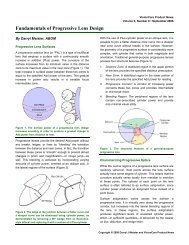
Progressive Addition Lenses<br />
Progressive addition lenses (PALs), commonly referred to as no-line bifocals or<br />
varifocals, are a gradient power lens used to treat presbyopia. PALs allow the viewer to<br />
avoid image jump caused by the abrupt change in power found in bifocal and trifocal<br />
lenses. The power in a PAL gradually changes from the top of the lens, which<br />
corresponds to the distance power of the lens, and the bottom portion of the lens which<br />
corresponds with the near power of the lens. However, this gradual change in power<br />
comes at a cost. The vision outside of the optimal viewing areas of the lens suffers from<br />
distortion, although the problem is more accurately referred to as aberrations with<br />
distortion being one of the aberrations induced.<br />
History<br />
The first patent for a PAL was filed in Britain in 1907 by Owen Aves (Patent 15,725); the<br />
design was for a conical back surface with a cylindrical front surface. The sum of the<br />
This document is licensed under the Creative Commons Attribution 3.0 License. 7/30/2009<br />
43
two surfaces of Owen Aves’ lens created a progression in power; however the design had<br />
one major flaw: it was difficult to include any cylinder power in the lenses so ultimately<br />
the design was never produced commercially. The first commercially available PAL was<br />
designed by Duke Elder in 1922 named the “Ultrifo”. This design utilized aspheric<br />
surfaces to create a progression in power. The next commercially available PAL was a<br />
lens called the Varifocal. Created by Offcine Galileo di Milano out of Italy in the 1950’s,<br />
the design was inspired by Aves’ design. Milano’s design is referred to as an “elephant<br />
trunk” design and utilizes only the front surface to create the progression in power. It<br />
wasn’t until 1959 that the first modern day progressive was born; the Varilux. The<br />
Varilux was developed by Bernard Maitenaz and produced by the Societe des Lunetiers<br />
(Essel) known today as Essilor. The first Varilux used a spherical near and distance<br />
section with an aspheric intermediate corridor that gradually changed in profile from the<br />
distance to the near. This design was crude but effective and is the basis for many of the<br />
modern designs seen today.<br />
Fitting Method<br />
Many manufacturers have fitting criteria available for their lens designs, however a good<br />
technique to follow is outlined below:<br />
1. Have patient chose frame, making sure the frame is fit close to the face with<br />
10mm -14mm of vertex distance.<br />
2. Adjust the nose pads to the patient’s nose. Apply 5°-10° of face form, and 10° –<br />
15° of pantoscopic angle to the lenses.<br />
3. Sitting directly across from the patient, aligned so that your eyes and the patients<br />
eyes meet on a plane parallel to the floor, mark the centers of the pupils on the<br />
demo lenses or a piece of clear tape placed across the frame.<br />
4. Measure the distance from the pupil center on the lens to the inside bevel of the<br />
bottom most portion of the eye wire. This is the segment height to specify for the<br />
lens.<br />
5. Use the manufacturers cut out chart to verify that the DRP, NRP, PRP are<br />
properly placed and within the confines of the frame.<br />
6. Take monocular IPD with a corneal reflex pupilometer. It is important to take an<br />
accurate measure for correct placement of the optics.<br />
Soft vs. Hard Design<br />
Progressive lens designs have been classified as hard or soft in the past with the newer<br />
generation of lenses exhibiting characteristics of both. Soft lenses are described as lenses<br />
where the astigmatism from the corridor is allowed to creep into the top distance portion<br />
of the lens or the bottom near portion of the lens. This allows the corridor to appear<br />
This document is licensed under the Creative Commons Attribution 3.0 License. 7/30/2009<br />
44
wider and less distorted making it easier for first time progressive lens wearers to adapt.<br />
Hard designs have clear peripheries in the top distance portion and bottom near portion<br />
which moves the peripheral distortion to the middle corridor section of the lens. Hard<br />
designs are more difficult for first time patients, however they provide wide near and<br />
distance areas which often make them a good choice for advanced presbyopes. Today’s<br />
lenses often employ multiple designs across a range of add powers varying from soft to<br />
hard. Most even combine characteristics to come up with hard distance and soft near<br />
sections or vice versa allowing multiple combinations to fit the patients particular needs.<br />
Manufacturing Process<br />
Progressive surfaces are described mathematically as deformed conicoids, these surfaces<br />
present certain problems in the traditional sense of ophthalmic molded lenses. Single<br />
visions and aspheric single vision lens molds exhibit rotational symmetry which means<br />
when a glass mold is created, the surface can be polished by rotating a tool of the<br />
opposite curvature at high speeds to polish the surface. However, with progressive<br />
surfaces the lenses do not exhibit this same rotational symmetry, so polishing in this<br />
manner would warp the surface and destroy the intended design. So to make a<br />
progressive mold the process used is called slumping. Slumping requires a clay mould to<br />
be created to the exact standards of the lens design and then a highly polished piece of<br />
glass is heated to just above flowing and allowed to slump or rest upon the clay mould<br />
until it takes on the profile of the clay mould. The mould is then tested to ensure that the<br />
accuracy. This process is not easy and requires precise temperature control and other<br />
metrics to ensure adequate reproduction of the intended design. In some cases the mould<br />
manufacturer will incorporate a vacuum assisted technique to suck the glass into the clay<br />
mould. Using this method the subtleties of the design can be lost just like the details of a<br />
photocopy of a photocopy to the original.<br />
The most recent manufacturing techniques incorporate CNC grinding of the design<br />
directly to the surface of the mould instead of using clay moulds. This allows more<br />
subtleties of the designs to remain. This is done with Computer Numerically Controlled<br />
generators and floating pad polishers. The generators use a single point diamond which<br />
leaves a smooth surface that requires little polishing and the floating pad system allows<br />
for minimum stock removal. This eliminates the issue of degradation from making a copy<br />
of a copy.<br />
The individual PAL designs utilize the same CNC process as the updated digital molding<br />
process except the progressive surface is directly scribed to the lens blank eliminating the<br />
molding process of the progressive surface. This allows any number of single vision semi<br />
finished lens blanks to be utilized in any number of material and treatment combinations.<br />
This document is licensed under the Creative Commons Attribution 3.0 License. 7/30/2009<br />
45
Prism Thinning<br />
Because of their design, the powers of a progressive lens vary from the top of the lens to<br />
the bottom of the lens, leading to differences in thickness. To reduce the difference in<br />
thickness, when the lenses are ground to specification, the lab will often incorporate<br />
prism. This process is referred to as equi-thinning, prism thinning, or yolk prism. The<br />
rule of thumb is to use 2/3 the add power in base down prism, however many labs employ<br />
more sophisticated software that can take into account the frame size, power,<br />
astigmatism, and segment height when making a determination for the amount of prism.<br />
It is a good idea to establish your preferences for equi-thinning with your lab up front<br />
then make alternate specifications should circumstances dictate. When changing one lens<br />
it is also important to inform the lab of the amount of prism present in the current lens so<br />
no imbalance is produced.<br />
Progressive Design Generations<br />
The Varilux design is the basis of all modern designs and as such we use their generation<br />
to describe all progressives.<br />
1 st Generation Designs: Outlined above; spherical distance zone, using a progression of<br />
conic sections to arrive at a spherical near. The lenses were rotated nasally to allow for<br />
inset. Sometime between the first and second generations the ideas of splitting the<br />
intermediate zones into nasal and temporal to create asymmetry was employed.<br />
2 nd Generation Designs: This generation moved away from spherical distance and near<br />
zones to aspheric zones which allowed the aberrations to be managed slightly better by<br />
moving some of the intermediate zone abberations into the distant periphery and some of<br />
the aberrations down into the near periphery. This created a wider intermediate zone that<br />
was more useable. This generation also focused on a concept called orthoscopy.<br />
Orthoscopy is minimizing distortion, mainly in this case along horizontal and vertical<br />
lines. This was accomplished by focusing on keeping the horizontal prismatic effect<br />
from varying along the periphery both nasally and temporally, as well as keeping the<br />
vertical prismatic effect from varying along the distance and near zones.<br />
3 rd Generation Designs: This generation of progressive lenses was the first to employ<br />
multi design principles in a series of progressive lenses. In the past the design was fixed<br />
for the entire progressive series. This meant that the design was chosen to be either soft,<br />
aberrations distributed throughout the entire lens, or hard, aberrations kept in the<br />
periphery of the progression zone. At this time there were different designs on the<br />
market with each manufacturer focusing their attention towards eliminating or managing<br />
certain aberrations better than others. These design philosophies can be thought of and<br />
This document is licensed under the Creative Commons Attribution 3.0 License. 7/30/2009<br />
46
seen as signatures which continue through modern designs (examples include the VIP<br />
which focused on wider distance and near zones keeping the astigmatism in the lens<br />
periphery of the intermediate zone, Truvision Omni which focused on reduced<br />
astigmatism by spreading it out over the entire surface of the lens, and the Zeiss Gradal<br />
HS which focused on more comfortable binocular vision). From these various designs<br />
came the concept of going from soft and easy for an early presbyope to hard with wider<br />
areas of vision for an advanced presbyope. The new design philosophies were combined<br />
into one progressive lens series with the design being a function of add power.<br />
4 th Generation Design: This generation employed a soft periphery combined with a short<br />
corridor. Previous designs had been plagued with the choice of a short corridor which<br />
allow the viewer a more comfortable posture when reading with the periphery being<br />
difficult to use, or a longer corridor with better dynamic vision through a softer periphery.<br />
This design also included variable insets which were based upon the add power.<br />
5 th Generation Design: This design focused on improvements in peripheral and binocular<br />
vision. This generation improved and enlarged the horopters (corresponding points on<br />
the retina where the two images viewed through the right and left lens form a single<br />
image) and peripheral vision. This was accomplished by varying the inset based not only<br />
upon the add power but also upon the distance vision through the base curve.<br />
6 th Generation Design: This is the current generation of lens design. These lenses<br />
incorporate all the design characteristics of the past while using beam tracing instead of<br />
ray tracing the lenses. In essence instead of focusing on the characteristics of one ray<br />
through one point on the lens the designer now focuses their attention on a beam the size<br />
of a pupil through the lens. This helps to reduce the effects of the lesser aberrations,<br />
coma, and spherical aberration. In the past these two aberrations have been ignored and<br />
for good reason since they provide only negligible improvements when corrected.<br />
However, with the technology of computers today it is possible and feasible to account<br />
for these aberrations. This generation of lenses is often referred to as high definition or<br />
high resolution lenses.<br />
Individual Designs: These designs are not necessarily a generation but they are the next<br />
step in the evolution of progressive lenses and follow chronologically after 6 th Generation<br />
Designs, individual lenses use digital or free form surfacing techniques along with<br />
sophisticated PAL design software and incorporate the patient’s biometric data,<br />
prescription, and frame attributes into the design of the lens. In the past, designs have<br />
used global variables for things such as back vertex, center of rotation, pantoscopic tilt,<br />
dihedral or face form angle, as well as insets. The individual designs take the patient’s<br />
correct metrics into account and factors them into the design. This means the patient gets<br />
a truly custom lens with minimal compromises due to manufacturing constraints. One<br />
manufacturer even goes as far as incorporating a metric for the amount of head tilt as<br />
This document is licensed under the Creative Commons Attribution 3.0 License. 7/30/2009<br />
47
compared to eye movement to vary the designs hardness for a more comfortable feel<br />
given the patient’s viewing habits. This stands out from the average individual design in<br />
that the variable becomes the research behind what makes the design comfortable rather<br />
than the designs and patient related parameters.<br />
Example of a 1 st Generation Design<br />
The distance can be described as a spherical surface with power (F D ) corresponding to the<br />
distance front surface measured in diopters and the near described as a sphere of power<br />
(F N ) corresponding to the near front surface power, then the corresponding radius of the<br />
lenses can be described as:<br />
r D = 1000/F D<br />
r N = 1000/F N<br />
With the corresponding points fitting into the spherical equation:<br />
x 2 +y 2 + z 2 = r D<br />
2<br />
these equations make the assumption the point (0,0,0) is the point at which the radius<br />
originates to wards a point on the corresponding spheres. Our domain for the distance<br />
could be easily described as above the prism reference point or y>0, and our domain for<br />
the reading could be easily described as y
Occupational Lenses<br />
In the broadest sense of the term, an occupational lens is any lens designed for a specific<br />
task aside from everyday, “general-purpose” lenses. This can be something as simple as<br />
a single vision computer lens with only one viewing area or as complex as a “double-D”<br />
trifocal lens with 5 separate viewing areas or anywhere in between.<br />
This section will help you to understand the different types of occupational lenses and<br />
how to determine which lenses will help your patient accomplish the tasks encountered in<br />
their daily life.<br />
Occupational lenses can be broken down into two main categories; single vision lenses<br />
with a set focal length for a specific task or multifocal lenses which will allow the patient<br />
to focus at two or more distances with the same lens. The multifocal category can be<br />
further broken down into lined and progressive addition lenses.<br />
Single Vision<br />
The single vision category of lenses includes those specifically for work done at a fixed<br />
distance. A computer lens will be set so the patient can see the computer monitor and<br />
keyboard easily, normally around 20-24 inches (50-60 cm). A reading lens will likewise<br />
be set so that the patient can comfortably read for long periods of time in their preferred<br />
position. This is usually set around 14-18 inches (35-45 cm). These will be the most<br />
common single vision occupational lenses that you will encounter. However, a lens can<br />
be made for viewing at any distance required by the patient. Using this information, we<br />
can also consider a jeweler’s loupe to be an occupational lens, though the focal length<br />
would be much shorter, around 8-12 inches (20-30 cm).<br />
Multifocals<br />
Lined multifocal lenses can cover a much wider area of application than the single vision<br />
variety. The most common lined multifocal occupational lens is the “Double-D” lens.<br />
This lens offers correction for distance vision as well as near just as a traditional bifocal.<br />
The added benefit of this type of lens is the addition of a second near vision segment on<br />
the top of the lens. This will allow someone such as a plumber, electrician, or mechanic<br />
to read information that is above the normal line of vision without having to tilt their head<br />
back to an uncomfortable or impractical angle to use the reading segment on the bottom<br />
of the lens. This type of lens is also available in an “executive” style (the segments<br />
stretch across the entire width of the lens), trifocal segments on both top and bottom,<br />
This document is licensed under the Creative Commons Attribution 3.0 License. 7/30/2009<br />
49
trifocal on the bottom and bifocal on top, or even with different addition powers in the<br />
top and bottom segments.<br />
A standard style bifocal or trifocal may also be made into an occupational lens. By<br />
changing the distance portion of a bifocal lens to the patient’s intermediate prescription<br />
and reducing the add power accordingly, you will allow your patient to see the computer<br />
monitor comfortably while still being able to read while working. A 14x35 mm trifocal<br />
set slightly higher than normal will give the same effect while also allowing distance<br />
vision through the top of the lens. You can also adjust the placement of the reading<br />
segment to allow your patient much more comfortable vision during certain sports. A<br />
golfer may prefer to have his reading segment set around 5 mm; just enough to see the<br />
scorecard without interfering with his swing. A shooter may want the segment of his<br />
glasses rotated nasally for a better view of the gun’s sights. These as well can be<br />
considered occupational lenses.<br />
Progressives<br />
The progressive type occupational lenses differ somewhat from the lined versions. A<br />
progressive lens being worn in an office environment may have distance vision set higher<br />
in the lens than normal and adjusted to focus at 10-12 feet (3-4 meters) while dedicating<br />
the majority of the lens to computer distance and reading. This will allow the patient to<br />
see across the office while seated at a desk while still giving the patient comfortable<br />
intermediate and near vision. This type of lens will also work well for concert musicians<br />
who need to be able to see the conductor as well as the music in front of them.<br />
Some new technologies also allow a combination of lined and progressive type lenses. It<br />
is now possible to have a progressive lens with a lined reading segment on the top of the<br />
lens. This would work very well for commercial pilots who not only need to see distance<br />
and near/intermediate below the normal line of sight but also need to see instruments<br />
located above them to properly do their job.<br />
Safety Lenses<br />
Safety lenses, or industrial lenses, fall into two primary categories: Basic and High<br />
Impact. These categories are defined by the American National Standards Institute<br />
(ANSI) and have been adopted by the Occupational Safety and Health Administration<br />
(OSHA).<br />
This document is licensed under the Creative Commons Attribution 3.0 License. 7/30/2009<br />
50
Basic impact lenses must:<br />
• Have a minimum center thickness of 3.0mm regardless of lens material; or<br />
• Have a minimum edge thickness of 2.5 mm if it is a+3.00D lens or higher<br />
• Pass a drop ball test of a 1 inch diameter steel ball dropped 50 inches<br />
• Sandblasted with the manufacturer’s identification<br />
• be delivered to the wearer bearing a Warning Label indicating that the protector<br />
only meets the Basic Impact Standard<br />
High impact lenses must:<br />
• Have a minimum center thickness of 2.5 mm regardless of lens material<br />
• Pass a high velocity test in which a ¼ inch steel ball is shot at a lens at 150<br />
ft/second<br />
• Sandblasted with the manufacturer’s identification and a plus (+) sign<br />
• Be manufactured from either polycarbonate, Trivex, or SR-91<br />
All safety lenses, whether they are basic or high impact resistant, must be inserted into a<br />
frame that meets the high impact lens standards. In addition, the frame must be marked<br />
with the Z87+ mark on the frame front and temple. These frames are able to retain a lens<br />
during high impact testing.<br />
The application of occupational lenses is nearly limitless. By determining the needs of<br />
your patients, you should be able to recommend a lens that will help to accomplish nearly<br />
any task encountered at work or play.<br />
Slab Offs<br />
Slab-off, or bicentric grinding, is a method of correcting vertical imbalance for patients<br />
with anisometropia. Anisometropia is a condition in which the eyes have unequal<br />
refractive power. Anisometropia may be caused by differing amounts of either myopia or<br />
hyperopia between the eyes. In some cases, one eye will be myopic while the fellow eye<br />
is hyperopic, a condition known as antimetropia. When this condition exists, unequal<br />
refractive powers result in differing amounts of induced prism as the eyes move away<br />
from the optical center of the lenses, often causing diplopia or double vision. This may<br />
be corrected by adding Base Up prism (slab-off) or Base Down prism (reverse slab-off)<br />
to one or both spectacle lenses.<br />
Slab-off is a technique in which the base-up prism is ground on half the lens in either the<br />
most minus or least plus lens. The finished lens looks like a portion has been cut from it,<br />
hence the name “slab-off.” In 1983, Younger Optics developed a pre-molded reverse<br />
This document is licensed under the Creative Commons Attribution 3.0 License. 7/30/2009<br />
51
slab-off lnes. A reverse slab-off adds Base Down prism to the least minus or most plus<br />
lens. The reverse slab-off lens was designed to aid in the difficulties of slab-off grinding.<br />
Producing a traditional slab-off lens requires great skill and is quite time consuming. By<br />
using a pre-molded reverse slab-off lens, cost and production time are both greatly<br />
reduced.<br />
Generally, vertical imbalance does not become troublesome for the patient until it reaches<br />
1.5 diopters of imbalance. Some patients are able to tolerate much more imbalance while<br />
others much less. To determine which eye will receive the slab-off and how much prism<br />
should be ground, you will need to find the lens power at the 90° meridian. This is<br />
calculated by using the oblique meridian formula or the table below (you will most likely<br />
have to round to the nearest 5°):<br />
Cylinder Axis % Cylinder Power @<br />
90°<br />
0 180 100<br />
5 175 99<br />
10 170 97<br />
15 165 93<br />
20 160 88<br />
25 155 82<br />
30 150 75<br />
35 145 67<br />
40 140 59<br />
45 135 50<br />
50 130 41<br />
55 125 33<br />
60 120 25<br />
65 115 18<br />
70 110 12<br />
75 105 7<br />
80 100 3<br />
85 95 1<br />
90 0<br />
This document is licensed under the Creative Commons Attribution 3.0 License. 7/30/2009<br />
52
Calculate a Slab Off<br />
Example:<br />
OD –5.75 –2.00 X 130<br />
OS –0.50 –1.00 X 025<br />
1. Determine the power of each lens in the 90° meridian.<br />
Using the table, you can find that the right eye has 41% of the cylinder power at 90° or -<br />
.82 diopters, giving total power at 90° of –6.57. The left eye has a total power of -1.32.<br />
Clearly we will be using the right lens for the slab off.<br />
2. Now we must determine the seg drop for the frame selected.<br />
This is done by dividing the ‘B’ measurement of the frame by 2 then subtracting the seg<br />
height. Add 5 mm to this to get the reading depth.<br />
‘B’ of frame = 50mm, seg height = 20<br />
½ of ‘B’ = 25 – seg height 20 = 5 seg drop<br />
5 + 5 = 10 this is the reading depth<br />
3. Apply Prentice’s Rule to determine the amount of vertical prism induced in each eye.<br />
To determine the amount of prism needed, we will use Prentice’s Rule. Multiply the<br />
power by the reading depth and divide by 10.<br />
OD -6.57 X 10 = 65.70 / 10 =6.57 diopters<br />
OS -1.32 X 10 = 13.20 / 10 =1.32 diopters<br />
For the total prismatic effect, we subtract the left from the right.<br />
6.57 – 1.32 = 5.25 diopters of correction needed.<br />
3. Conventional Slab Offs are always ground base up in the most minus or least plus<br />
powered lens in the 90° meridian.<br />
The process of bicentric grinding is very involved and will not be covered in this section.<br />
Cataract Lenses<br />
Prior to the introduction and prominent use of IOL’s (intra-ocular lenses) in the early<br />
eighties, Cataract lenses were regularly dispensed by opticians. Increasingly rare today,<br />
there is still a need for cataract lenses. While this section covers the topic of cataract<br />
lenses much of the information also applies to high plus lenses.<br />
This document is licensed under the Creative Commons Attribution 3.0 License. 7/30/2009<br />
53
A cataract is an opacity in the crystalline lens of the eye; a cloudiness that occurs in some<br />
of us as we age. To restore clarity, cataract surgery is performed to remove this natural<br />
lens from the eye. Without the crystalline lens, the eye loses its natural ability to focus<br />
and is referred to as aphakic. Most cataract surgeries today are followed by the insertion<br />
of an intra-ocular lens, also known as an IOL, which helps restore the eye’s ability to<br />
focus. An eye with an IOL implant is called pseudo-phakic.<br />
There are many things to consider when helping a patient with cataract lens needs. The<br />
first thing to consider is frame selection. Lens size and fit are particularly important since<br />
material availability is limited. Cataract lenses generally fall in the +12.00 D to +16.00 D<br />
power range (sometimes higher) which means the finished glasses will have considerable<br />
weight.<br />
The ideal frame will have a relatively small eye size and a frame PD very close to the<br />
patients PD. The more the lens is decentered, the thicker it will be, particularly at the<br />
nasal area. A good rule of thumb is to select a frame PD within 4 mm of the patients PD.<br />
A round shape is also a good choice for cosmetic reasons. If the B measurement is<br />
significantly smaller than the A measurement, the lenses will have a thick shelf on the top<br />
and bottom. Once again, a good rule of thumb is to keep the A and B measurement within<br />
at least 6 mm of each other.<br />
Metal frames allow some latitude in customizing the fit. However, a well fitting plastic<br />
frame can often offer the patient more comfort and improved appearance. Plastic frames<br />
also tend to sit closer to the eye which reduces magnification contributing further to<br />
improved vision and appearance.<br />
With higher powers, vertex distance is another important consideration. The prescribing<br />
Dr. should indicate on the Rx the refracted distance. The refracted and worn vertex<br />
distances should match otherwise, vertex compensation must be performed. If the lenses<br />
are worn closer than the refracted distance, the lens powers need to be made stronger.<br />
Likewise, if the lenses are worn further from the eye than refracted distance, the lens<br />
powers need to be made weaker because of the additional magnification.<br />
Lens selections and designs<br />
Cataract lenses are available in single vision, but this category is seldom used for an<br />
aphakic unless the patient wants near only or distance only. Once again, when a patient<br />
losses his natural crystalline lens, he also loses the ability to naturally focus on near and<br />
distance objects. Therefore, if a patient wants to see both far and near out of one pair of<br />
glasses, he will need a multi-focal lens of some type.<br />
This document is licensed under the Creative Commons Attribution 3.0 License. 7/30/2009<br />
54
The first multi-focal lens type we will discuss is the lenticular. Lenticular cataract lenses<br />
have a similar shape to an egg sunny side up. The outside of this design (the white of the<br />
egg) is called the carrier. The carrier is a flat, non-specific powered area which serves to<br />
support the central viewing area of the lens.<br />
The central viewing area of a lenticular design (the yoke of the egg), also known as the<br />
aperture, is much steeper and holds the base curve upon which the back curve is<br />
calculated for the desired lens power. The aperture can be either spherical or aspheric.<br />
Lenticular design cataract lenses are best used when the patient’s frame chooses a large<br />
frame or the desired power is high (greater than +15.00 D). The carrier region of a<br />
lenticular improves cut out options and edge thickness. Higher add powers also are<br />
generally more available in this type design.<br />
Cataract lenses are also available in full field designs. Full field designs have no carrier<br />
and are most often aspheric. Asphericity in these high powered lenses greatly improves<br />
optics and cosmetics. Most patients will notice wider, more natural vision wearing a full<br />
field design. They will also look better cosmetically since there is no carrier.<br />
The last lens to discuss is called the Super Modular. This is an aspheric designed lens that<br />
is a cross between a lenticular and full field. Rather than a distinct carrier, this lens<br />
utilizes a rapid aspheration on the outer edges, making the transition from the aperture to<br />
the carrier seamless. This lens availability often allows for higher power than full fields.<br />
This lens is best used when high correction is required with better cosmetics than a<br />
lenticular.<br />
Chapter 5: FRAMES<br />
The Boxing System<br />
In 1962 the <strong>Optical</strong> Manufacturers Association adopted the boxing system to provide a<br />
standard for frame and lens measurement that greatly improved upon the accuracy of<br />
previous systems. The boxing system is based upon the idea of drawing an imaginary box<br />
around a lens shape with the box's sides tangent to the outer most edges of the shape. The<br />
system uses the sides of the boxes as reference points for the standard system of<br />
measurements.<br />
This document is licensed under the Creative Commons Attribution 3.0 License. 7/30/2009<br />
55
"A" Measurement - The horizontal distance between the furthest temporal and nasal<br />
edges of the lens shape or the distance between the vertical sides of the box. The A<br />
measurement is also commonly known as the eyesize.<br />
"B" Measurement - The vertical distance between the furthest top and bottom edges of<br />
the lens shape or the distance between the horizontal sides of the box.<br />
Datum Line - The horizontal line that runs through the vertical center of the frame.<br />
Geometric Center (GC) - The intersection of the Datum Line and horizontal centers of<br />
each lens shape.<br />
Distance Between Lenses (DBL) - The shortest distance between the nasal edges of each<br />
lens or the distance between boxes. DBL is also commonly referred to as bridge size.<br />
Distance Between Centers (DBC) - The horizontal distance between the geometric<br />
centers of the lenses. DBC is also know as the Geometric Center Distance (GCD), but<br />
more commonly referred to as the frame PD. In theory the DBC can be calculated by<br />
adding the "A" Measurement to the DBL as marked on the frame, however in practice the<br />
calculation may differ from the actual measurement.<br />
Note: Frames are typically marked for size, for example: 54-18, where 54 is the "A"<br />
Measurement and 18 is the DBL.<br />
This document is licensed under the Creative Commons Attribution 3.0 License. 7/30/2009<br />
56
Effective Diameter (ED) - Twice the distance from the geometric center of the lens<br />
furthest edge of the lens shape. The ED can also be defined as the smallest diameter lens<br />
that would cutout, if the frame's geometric center matched the lenses optical center. ED is<br />
used in combination with decentration distance to select the minimum lens blank size<br />
required to fit a given frame.<br />
Seg Height - The vertical distance between the bottom edge of the box and the top of the<br />
bifocal or trifocal segment<br />
Seg Drop - The vertical distance between the Datum line and the top of the bifocal or<br />
trifocal segment Overall<br />
Temple Length (OTL) - The running distance between the middle of the center barrel<br />
screw hole and the end of the temple.<br />
Length to Bend (LTB) - The distance between the center of the barrel and the middle of<br />
the temple bend.<br />
Front to Bend (FTB) - The distance between the plane of the front of the frame and the<br />
temple bend. Used if there is a significant distance between the frame front and the<br />
beginning of the temple.<br />
Frame Styles and Materials<br />
What makes up a frame?<br />
It is very important to know what components make up various frames. You will need to<br />
know which specific part you are talking about when ordering replacement parts, when<br />
describing a frame for a manufacturer or sales representative, when conveying<br />
information to a fellow optical dispensing professional, or when speaking with lab<br />
personnel. Failing to accurately describe the part you need could create delays, cause<br />
increased shipping costs, and create waste.<br />
Some frame parts may be called different names by different people, some terms only<br />
apply to plastic frames and some apply only to metal. Some terms do not apply at all<br />
when discussing three-piece mounts (see below) made of hinge-less flexible metal.<br />
However, here are the generally accepted terms and their meanings:<br />
Chassis (also known as frame front): When connected by a solid bridge of any kind<br />
(metal or plastic), the chassis is the combination of eyewires, bridge and the end pieces.<br />
This document is licensed under the Creative Commons Attribution 3.0 License. 7/30/2009<br />
57
This includes any crossbars above the bridge, and any artful details applied to any of<br />
those pieces (like rhinestones).<br />
Temples (also known as temple arms or arms): Temples are the pieces that hold the<br />
chassis to the head and ears. The temple is the piece that runs from the end piece on the<br />
chassis back to behind the ear. The temple also holds half the hinge assembly. (Also, see<br />
temple types, below.)<br />
Temple tips: Temple tips are usually removable plastic sleeves that slip over the ends of<br />
metal temples to provide comfort for the wearer. On plastic frames, the temple tip is the<br />
part of the temple that goes behind the ear. (Also see chapter 11)<br />
Bridge: The bridge is the area between the two eyewires. On a plastic frame, it is the area<br />
that touches the nose and the area that connects the two eyewires together. On a metal<br />
frame, it is only the area that connects the two eyewires together. On a three-piece mount<br />
it is the entire assembly that connects the two eyewires together in the middle.<br />
This document is licensed under the Creative Commons Attribution 3.0 License. 7/30/2009<br />
58
Nose pads: Nose pads are the small pads designed to contact the nose and hold the frame<br />
up off the nose and away from the face.<br />
Guard arms: Guard arms are the small wire arms that actually hold the nose pad in<br />
place.<br />
This document is licensed under the Creative Commons Attribution 3.0 License. 7/30/2009<br />
59
Eyewire: The eyewire is the area of the frame that actually surrounds the lens and holds<br />
the lens in place.<br />
End piece: The end piece is the area of the chassis that meets the temple or the point<br />
where the temple attaches to the chassis. It is where half the hinge is found.<br />
This document is licensed under the Creative Commons Attribution 3.0 License. 7/30/2009<br />
60
Hinge: The hinge is the point where the temple is connected to the chassis. It allows the<br />
temple to fold in and out. The hinge is usually held in place by a screw, but may be<br />
secured by a ball-and-socket or other variation. Also see ‘hinges’ below.<br />
Frame Materials<br />
There are two basic kinds of frame materials: metals and plastics.<br />
Metals have four general types:<br />
1. Monel, or basic nickel-based metal frames. These are inexpensive and make up the<br />
bulk of all low and mid-range metal frames made today. If a frame is metal and not<br />
flexible or not marked ‘stainless steel’ or ‘titanium,’ chances are excellent it is a Monelbased<br />
frame.<br />
This document is licensed under the Creative Commons Attribution 3.0 License. 7/30/2009<br />
61
Advantages of Monel-based frames:<br />
• Easy to adjust<br />
• Hold adjustments well<br />
• Very strong<br />
• Relatively light in weight<br />
• Can have a wide range of colors and plating like bright gold and bright silver<br />
• Economical<br />
• Can be repaired by solder.<br />
Disadvantages of Monel -based frames:<br />
• Outermost plating (the layer that touches the skin) can wear off, which can cause<br />
skin allergies or reaction to nickel in Monel metal<br />
• Prone to breaking after repeated bending<br />
• Once plating is worn away, metal may erode quickly and create abrasive areas<br />
and sharp edges<br />
• Monel is the heaviest of metal frame materials in use.<br />
2. Stainless steel is used in many mid-range to high-end frames. If a frame is metal and<br />
looks as if it is made of a material just a little thicker than a paper clip, then chances are<br />
excellent that it is made from stainless steel. Most frames will be marked on the demo<br />
lenses Stainless or Stainless Steel and may be marked on the inside of the temple as well.<br />
This document is licensed under the Creative Commons Attribution 3.0 License. 7/30/2009<br />
62
Advantages of stainless steel frames:<br />
• Light in weight because of reduced material<br />
• Very strong<br />
• Very little chance of allergic reaction to metal<br />
• Holds color well<br />
• Attractive appearance<br />
• Holds adjustments very well.<br />
Disadvantages of stainless steel frames:<br />
• Limited range of colors<br />
• Colors tend to be matte in finish<br />
• Temples rarely made in any shape other than “paper clip”<br />
• Larger frames can become heavy.<br />
3. Titanium is used in many mid-range and many high-end frames. Since it comes in a<br />
wide range of colors, plating, and styles, it is not always possible to spot a titanium frame<br />
unless it is marked as such. Its extreme light weight may tip you off. A titanium frame of<br />
equal size may weigh half as much as an identical frame in Monel.<br />
Advantages of titanium frames:<br />
• Titanium is hypo-allergenic: it will not cause reactions with skin<br />
• It is extremely lightweight<br />
• It is 100% corrosion proof<br />
• Extremely durable. A well-made titanium frame can last for years<br />
• Very strong.<br />
Disadvantages of titanium frames:<br />
• Titanium is not easy to manufacturer, and not all companies provide the same<br />
quality of production<br />
• Frames can be legally labeled 100% titanium yet contain other metals<br />
• Frame lines may be inconsistent in their quality. Just because a frame is ‘titanium’<br />
does not mean it is a quality product.<br />
This document is licensed under the Creative Commons Attribution 3.0 License. 7/30/2009<br />
63
• Adjustments can be tricky. If a frame is 100% titanium, it can break easily at weld<br />
points if not well made<br />
• A well-made titanium frame can last for years which might discourage repeat<br />
sales<br />
4. Flexible or memory metals are metals with flexible properties, and are usually a mix<br />
of titanium and other metals. These frames will either be all flex-metal throughout the<br />
entire chassis and the entire temple, or a mixture of rigid areas and flexible metal. Flex<br />
metal frames are generally high-end and expensive. They are extremely popular for use in<br />
children’s frames for obvious reasons. Just like titanium frames, not all flex metal frames<br />
are created equal. Many lower-end frames offered with memory metal, do not have the<br />
same quality of higher-end ones. Brand names for flexible metal frames include, Flexon,<br />
Flexolite, Easy Twist, MagicTwist, HyperFlex, etc.<br />
Advantages of flex metal frames:<br />
• Bend instead of break<br />
• Return to original shape after being bent<br />
• Have spring-like quality that helps hold glasses in place on head<br />
• Lightweight.<br />
Disadvantages of flexible metal frames:<br />
• If not well designed with adjustment points built in, frames may be impossible to<br />
adjust<br />
• You may find fitting difficult on people with unusual or very asymmetrical face<br />
shapes<br />
• Some patients cannot adapt to a flexible frame; they actually need to feel the<br />
frame on their nose!<br />
• People (especially children) may incorrectly assume that the frame is<br />
indestructible, or that it can be bent repeatedly without damage.<br />
This document is licensed under the Creative Commons Attribution 3.0 License. 7/30/2009<br />
64
Plastics really have one general category, and then an odd collection of other materials.<br />
1. ‘Zyl,’ or Zylonite, makes up the bulk of all plastic frames on the market today. If<br />
a frame is plastic, chances are excellent that is Zyl.<br />
Advantages of Zyl frames:<br />
• Light in weight<br />
• Huge range of colors<br />
• Strong<br />
• Fairly easy to adjust<br />
• Can be molded in any shape and size<br />
Disadvantages of Zyl frames:<br />
• Can lose shape and even be ruined by high heat (dashboard of car in direct sun)<br />
• Will discolor over time<br />
• Will dry out and become brittle over time<br />
• Will stretch out and lose fit in hot weather.<br />
The generic category of plastic frames also includes brand names like SPX, and<br />
Grilamide. Which are variations of Zyl that are slightly lighter in weight, slightly more<br />
flexible, and have a little greater range of colors available. These Zyl hybrids are prone to<br />
heat damage, and can snap or split if over-stressed.<br />
Other materials in the plastic category have included:<br />
• Carbon: These were lightweight and strong but nearly impossible to adjust and<br />
never really took any substantial market.<br />
• Nylon: These were strong but quite heavy and also nearly impossible to adjust.<br />
• Rubber: Still found in swim goggles and as parts of frames but not used for<br />
complete chassis.<br />
This document is licensed under the Creative Commons Attribution 3.0 License. 7/30/2009<br />
65
• Optyl: This is one of the few materials that enjoyed a substantial market share for<br />
several years. Frames made of Optyl will usually be marked OPT or Optyl on<br />
their temple.<br />
• Polycarbonate: Strong and extremely lightweight it is used in sport safety<br />
eyewear.<br />
• Kevlar: These were lightweight and strong but nearly impossible to adjust and<br />
never really took any substantial market.<br />
A recent addition to the plastic category is flex plastic. It has all the advantages and<br />
disadvantages of flex metal with the added advantage of even greater weight savings.<br />
Note: Manufacturers will often mix several materials in a single frame. When a frame<br />
has a mix of materials – for instance, metal temples and a plastic front -you note the<br />
frame material by the chassis or frame front. The lab will need to know the material of<br />
the eyewire, in order to set their machines in the correct mode for cutting out the lenses.<br />
Frame Selection<br />
Although being fashionable and looking good are important, nothing is more important<br />
when dealing with frames than how they fit. Remember the old snowflake metaphor?<br />
“People are like snowflakes…every one of us is different?” Well, you will learn this is<br />
true when you start fitting eyeglasses! Frames either fit, or they do not. You cannot make<br />
a frame designed for a child fit a grown man. Frames come in a wide variety of sizes.<br />
Each manufacturer’s different lines will cater to different sizes. Large frame<br />
manufacturers will often offer each frame in three sizes, such as 49, 51, and 53. Smaller<br />
frame companies and specialty frame makers usually offer their frames in just one size.<br />
This document is licensed under the Creative Commons Attribution 3.0 License. 7/30/2009<br />
66
We are often asked if the frames on our board are divided by gender, which leads to<br />
thinking about what makes a men’s frame different from a women’s frame. To spot a<br />
traditional men’s frame look for features like a cross bar over the bridge, traditional gold<br />
and silver plating, aviator shapes, sharp angular shapes, and very large eye sizes. To<br />
identify a traditional women’s frame look for pinks and bright colors, decorative stones,<br />
and especially artful details on the temples or chassis. Everything else on the board falls<br />
into the unisex category! However even some “unisex” models seem to lend themselves<br />
towards one gender or another. Any frame with a cat-eye or accentuate upper temporal<br />
corner of the eyewire is definitely feminine.<br />
Frame Shape<br />
Although fairly self-explanatory frame shapes fall in to three general categories, round,<br />
rectangle, and oval. When describing a frame or eyewire as round it is assumed that the<br />
eyewire will be an almost perfect circle. When describing a rectangular frame or eyewire<br />
it is assumed that the horizontal and vertical lines of the frame will be approximately 90<br />
degrees apart from each other and that they will meet at what could best be described as a<br />
corner not a curve. The oval category will be longer across the A than across the B and<br />
will not have any distinguishable corners or straight lines. Within the categories you will<br />
see and hear frames being labeled as “modified” or as being a variation of one shape or<br />
another.<br />
Note: Frames have a base curve just like lenses do. Some prescriptions do not do well in<br />
certain frames. The higher plus the prescription the steeper or more curved the lens will<br />
be. A minus prescription will have little or no curvature of the lens. Should a frame be<br />
very flat (having very little face form) it will not hold a plus lens well. The reverse is true<br />
when we consider minus lenses in heavily wrapped shapes like sport sunglasses. One of<br />
the primary sources of lab delays is poor prescription – frame matching. If in doubt send<br />
the frame to the lab and get approval before promising a customer that it can be done.<br />
Poor Rx - Frame matching is one of the most common reasons for jobs to be delayed<br />
at the lab!<br />
Primary Frame Fitting Considerations<br />
The first thing to consider when fitting a frame to a patient’s head is the width of the<br />
frame. This means how the temples fit the sides of the patient’s head. A properly fitting<br />
frame will have its temples leave the frame front, or chassis, and go straight back,<br />
touching the person’s head just before their ear. There is simply NO EXCEPTION to this<br />
rule.<br />
This document is licensed under the Creative Commons Attribution 3.0 License. 7/30/2009<br />
67
A frame that is too slightly too tight or too narrow may feel quite good to the patient<br />
when they first try it on. However, it will shortly begin to give them trouble by sliding<br />
down their nose in a short period of time. A frame that is much too loose or too wide will<br />
slide down their nose immediately.<br />
Note: One good clue that a frame is too small is when a frame has spring hinges and they<br />
are partially open when the frame is on. Spring hinges are only there to provide flex when<br />
taking the glasses on and off or when they are struck. SPRING HINGES HAVE<br />
NOTHING TO DO WITH THE FIT OR COMFORT OF A PAIR OF GLASSES!<br />
Temples should never be bent to curve around a person’s head (unless provided by the<br />
manufacturer as part of the design of the frame), and they should never angle out from<br />
the chassis to reach the ear. Temples that are bent in or out mean that the frame DOES<br />
NOT FIT. This is where frame size comes into play: Should your frame be just a little too<br />
small, and it is marked 46 – 19, then check your catalog or call the manufacturer and see<br />
if it comes in a 48 – 20. If larger size is not available, then find another frame that fits!<br />
Temples come in three types, with the “skull” temple being the most prevalent found on<br />
95% of all glasses. It has a temple end that bends around the back of the ear, ends<br />
approximately mid-ear, and then bends in slightly towards the head, hugging the skull.<br />
The second type is a cable temple, found on shooting glasses, glasses for infants, and<br />
some safety glasses. It has temple ends that are sprung and that wrap around the entire<br />
ear, holding the glasses firmly in place. Because they are springs, they can and will<br />
weaken over time, and can also break.<br />
This document is licensed under the Creative Commons Attribution 3.0 License. 7/30/2009<br />
68
The last temple type was once called a “library” temple. This temple goes straight back,<br />
hugging the skull above the ear, never curving down at all. Originally these were popular<br />
for reading glasses, before progressive lenses made it unnecessary for people to take their<br />
glasses off frequently. Now, many modern designs have returned to this style of temple<br />
for fashion, but they are not given a special name. Many modern sport sunglasses also<br />
use a straight back design without any special designation. Frames designed for use under<br />
a helmet may also make use of a temple that goes straight back.<br />
Many temples are offered with “spring hinges” which are built into the temple end near<br />
where it meets the chassis. Placing the spring in the hinge allows it to be forced open<br />
several millimeters without damaging or bending the frame. Spring hinges are an<br />
excellent addition to a frame however they increase weight, they can freeze and break,<br />
and they should be lubricated from time to time with a very light oil.<br />
This document is licensed under the Creative Commons Attribution 3.0 License. 7/30/2009<br />
69
Second, we must consider how the frame fits the patient’s nose. Consider whether the<br />
frame is a plastic one with a molded solid bridge, or a metal one with adjustable nose<br />
pads. If the frame is plastic and has a solid bridge (almost all do), then the frame either<br />
fits, or it does not. There is simply NO EXCEPTION to this rule. Look at the patient’s<br />
nose, and see how the frame fits it. If the frame contours the nose well and has great<br />
contact across the entire bridge, then it fits. If you can see gaps or light showing between<br />
the nose and the bridge then it does not fit, and the patient must choose another frame. If<br />
the patient loves the frame, this may put you in an uncomfortable position, but remember<br />
that you are the optical dispensing professional and should be able to explain your<br />
reasons that the frame does not fit and the problems that will cause.<br />
This document is licensed under the Creative Commons Attribution 3.0 License. 7/30/2009<br />
70
NO! This plastic frame makes very little contact with the patient's nose. In fact because<br />
of its design it actually only touches at the two sharp points of the "keyhole" and would<br />
be uncomfortable to the wearer.<br />
YES! This is a much better plastic frame fit. Notice how the curve of the frame matches<br />
the curve of the patient's nose. You want maximum contact and do not want to see gaps<br />
or "daylight" between the nose and frame bridge.<br />
If the frame is metal and has adjustable nose pads, be sure the pads are sitting<br />
comfortably on the nose, are not too far apart or too close together. Simply look at the<br />
This document is licensed under the Creative Commons Attribution 3.0 License. 7/30/2009<br />
71
pads and be sure they are touching the nose as much as possible. If they are not, you will<br />
need to adjust them.<br />
Watch your frame manufacturers for designs that have narrow or wide bridges. Many<br />
manufacturers will develop their entire line, or one of their individual lines, for people<br />
with very wide or very narrow noses. You may find a line with consistent DBL<br />
measurements of 20, 21, and 22, and another with consistent DBL measurements of 15,<br />
16, and 17. Keep this in mind as you learn your frame boards, so you will be able to<br />
quickly guide your patients towards great-fitting frames. It is a fine line between<br />
adjustability and a frame with a bridge that is simply too wide or too narrow.<br />
NO! In this figure the nose pads are spread much too wide apart or flat for the patient's<br />
bridge or nose. Notice that the bridge is actually resting on the patient's nose. Also note<br />
how low the frame sits and high the eye is within the eyewire opening.<br />
NO! In this figure the pads are pulled too close together or are angled to straight for the<br />
patient's bridge or nose. Overall contact with the patient's nose is quite poor and they<br />
would have a sore spot in no time at all.<br />
This document is licensed under the Creative Commons Attribution 3.0 License. 7/30/2009<br />
72
YES! In this figure the pads are making good contact with the patient's nose. In particular<br />
look closely at the pad for the right eye (left eye in the picture) that is EXACTLY what<br />
you want to see, including the exposure of the pad and guard arm when viewing the<br />
patient.<br />
Nose pads come in a huge variety of shapes, materials and sizes (more in Chapter 11).<br />
Guard arms are provided so you can adjust the fit of the frame on the patient via the nose<br />
pads. You can change nose pad types to accommodate frame fit, but a frame that requires<br />
a lot of work to achieve a good fit is probably not the right frame to begin with.<br />
Rarely, will plastic frames will come wth nose pads. There is nothing special about these<br />
plastic frames, treat them as you would a metal frame with nose pads.<br />
Some metal frames have solid bridges with plastic inserts that either screw in or snap into<br />
place, covering the entire bridge area of a metal frame. These solid bridges eliminate nose<br />
pads and guard arms while they mimic the fit and feel of a plastic frame while providing<br />
the advantages of a metal one. Check fit of metal frames with solid bridges as you would<br />
a plastic frame.<br />
This document is licensed under the Creative Commons Attribution 3.0 License. 7/30/2009<br />
73
Third, check that the temples are long enough to curve over the ear properly and hold the<br />
glasses in place. This is often overlooked by even the most seasoned optical dispensing<br />
professional. For some reason, we seem to forget to check behind the ear and see if the<br />
temples are too short. If we sell a frame with temples that are too short, and a longer<br />
version is not available from the manufacturer, then we risk remaking a pair of glasses.<br />
Many temples can be shortened (see Chapter 11) but few can be lengthened. You may be<br />
able to slide a temple tip approximately 5 millimeters off the temple and maintain a<br />
normal bend effectively creating a longer temple.<br />
Develop the habit of performing these checks now, and remember the rule of three:<br />
One -- Width<br />
Two -- Nose<br />
Three -- Temple length<br />
This document is licensed under the Creative Commons Attribution 3.0 License. 7/30/2009<br />
74
Secondary Frame Fitting Considerations<br />
After determining that the frame is the appropriate width, has a good fit on the nose, and<br />
that the temples are long enough, we need to consider a few other things.<br />
For cosmetic appearances, it is best to choose a frame with a frame PD (A + DBL) as<br />
close to your patient’s PD as possible. Try to keep your patient’s eyes well centered in<br />
each eyewire opening.<br />
Also keep in mind the smaller the eyesize, the thinner and lighter the lens will be.<br />
This document is licensed under the Creative Commons Attribution 3.0 License. 7/30/2009<br />
75
For cosmetic reasons, when a prescription is high plus or minus avoid round shapes and<br />
go towards frame shapes with more angular dimensions or traditional ovals. This helps<br />
diminish the “bug-eye” appearance created by plus lenses’ magnifying power, and it<br />
helps reduce the appearance of myopic rings (visible distortions) in highly minifying<br />
lenses (greater than - 5.00). Also see chapter 3 on lens materials. Using the proper lens<br />
material and aspheric base curves will greatly reduce the cosmetic appearance of high<br />
powered lenses.<br />
Fitting and Adjustment<br />
As optical professionals, there are two distinct times when we fit and adjust a patient’s<br />
eyewear. The initial dispense when the patient is putting on their glasses for the first time<br />
and when the patient returns because their glasses are no longer fitting properly due to<br />
routine wear or damage. The tools and techniques we use are the same for both cases.<br />
Let’s begin with the initial dispense.<br />
Standard or Bench Alignment<br />
Four Point Touch<br />
When a frame comes out of the lab for final inspection, it should be in standard or bench<br />
alignment.<br />
Standard frame alignment – four point touch<br />
This means that when the frame is placed on a flat surface upside down, both eyewires<br />
and the crest of each temple should rest on the surface. When the frame is turned over,<br />
both eyewires and temple tips should touch the surface. The temples should be near<br />
parallel and the frame should have slight face form and pantoscopic tilt.There should be<br />
no X-ing of the eyewires (twisting of the bridge).<br />
The lenses should be in the same plane and the same height.<br />
This document is licensed under the Creative Commons Attribution 3.0 License. 7/30/2009<br />
76
Frame Misalignment<br />
X-ing<br />
Skewed out of coplanar alignment<br />
OD skewed higher than OS<br />
Improper temple fold alignment<br />
Proper temple fold alignment - When the temples are<br />
closed, they should overlap and be near parallel with the<br />
top of the frame.<br />
This document is licensed under the Creative Commons Attribution 3.0 License. 7/30/2009<br />
77
If the frame has nose pads they should be symmetrical and have slight frontal, splay and<br />
vertical angles (complete descriptions to follow). The width should be slightly narrower<br />
than the contours of the eyewire.<br />
Proper standard nose pad alignment<br />
The price sticker should be removed and the residue cleaned. This is a good start on the<br />
way to the final adjustment and will give the patient confidence that we are professionals.<br />
An out of alignment and unclean frame put on the patient’s face can give them doubts<br />
about the quality of our work and the value they are receiving for the money they spent.<br />
The Fitting Triangle<br />
When the frame is put on the patient’s face, it touches at three points: The junction of<br />
each ear and the skull and the bridge of the patient’s nose.<br />
This document is licensed under the Creative Commons Attribution 3.0 License. 7/30/2009<br />
78
Temple Fit<br />
Ideally, the temples should go straight back, touching the sides of the patient’s head as in<br />
example C above. They should not put pressure on the sides of the head as in example A.<br />
Nor should they bow out from the patient’s head as in example B. With today’s smaller<br />
frame sizes particularly on patients with larger heads, sometimes it is necessary to angle<br />
the endpieces of the temples out and curve them around the head as in example D.<br />
Pantoscopic Tilt<br />
Ideally, for good cosmetics and optics, there should be about 8 - 10 degrees of<br />
pantoscopic tilt for most frames.<br />
This document is licensed under the Creative Commons Attribution 3.0 License. 7/30/2009<br />
79
Face form<br />
There should also be slight positive face form, particularly if the patient’s PD is narrower<br />
than the frame PD (A measurement + dbl), the most common situation.<br />
Positive face form No face form Negative face form<br />
Fitting the bridge<br />
With a plastic frame only minimal adjustments can be made to the bridge. Care should be<br />
taken during frame selection to ensure a proper fit. The sides of the bridge should come<br />
in contact with the length of the nose. A frame that has a wider bridge than the patient’s<br />
nose rests on the top of the nose and will be uncomfortable and will slip.<br />
Adjustable nose pads should be adjusted so the frame sits comfortably on the patient’s<br />
bridge with the pupils falling slightly above the vertical center of the frame.<br />
There are four basic adjustments that can be made to adjustable nose pads. In every case,<br />
adjustments should be made to bring the maximum surface area of the pad in contact with<br />
the patient’s nose. Use the nose pad pliers for these adjustments<br />
Width – The horizontal distance between the pads when viewed from the front.<br />
Frontal angle – The angle of the pads when viewed from the front of the frame. The tops<br />
of the pads should be slightly closer together than the bottoms of the pad following the<br />
contours of the nose as it gets wider from top to bottom.<br />
Splay angle – The angle of the pads when viewed from the top of the frame. The front<br />
edges of the pads should be closer together than the back edges.<br />
This document is licensed under the Creative Commons Attribution 3.0 License. 7/30/2009<br />
80
Vertical angle – The angle of the pads when viewed from the side of the frame. Since<br />
most frames will have some amount of pantoscopic tilt, the bottoms of the pads should be<br />
slightly closer to the frame front than the tops.<br />
There are two other adjustments that aren’t used nearly as often. The first of these is the<br />
cal height of the nose pads relative to the vertical center of the frame. This is a much<br />
more difficult adjustment and should only be used to raise or lower multifocal segments<br />
and or optical center heights. The second of these is the distance between the nose pads<br />
and the frame front. Occasionally this distance should be decreased to optimize the<br />
keyhole effect and decrease peripheral distortions.<br />
Fitting around the ears<br />
When fitting temples, it is necessary to touch the patient’s face and ears. Always let the<br />
patient know that you are about to touch them. If they are surprised, it can make them<br />
uncomfortable. Say something like “I need to check the fit of the frame around your<br />
ears.”<br />
The temple bend should occur just behind the junction of the top of the ear and the skull.<br />
The temple should then follow the contour of the bone behind the ear (the mastoid),<br />
touching, but not putting pressure there. There should also be no pressure on the soft<br />
tissue on the back of the ear. With a proper temple bend, the end of the temple should fall<br />
about one half to two thirds down the length of the ear.<br />
When checking the fit of the temples, you should manually feel the fit behind the<br />
patient’s ears. It is also helpful to have the patient turn their head and bend the top of the<br />
ear forward to see the fit. Gently pull forward on the front of the frame while it is on the<br />
patient’s face to check for slippage.<br />
This document is licensed under the Creative Commons Attribution 3.0 License. 7/30/2009<br />
81
Commonly Required Frame Alignments<br />
Left lens is higher -<br />
Right lens is higher -<br />
Left lens is lower -<br />
Right lens is lower -<br />
Left lens is farther in -<br />
Left lens is farther out -<br />
Right lens is farther in -<br />
Right lens is farther out -<br />
Bend left temple up, or right temple down.<br />
Bend right temple up, or left temple down.<br />
Bend left temple down, or right temple up.<br />
Bend right temple down, or left temple up.<br />
Bend left endpiece in or right endpiece out.<br />
Bend left endpiece out or right endpiece in.<br />
Bend right endpiece in or left endpiece out.<br />
Bend right endpiece out or left endpiece in.<br />
Use whichever adjustment will bring the fit the closest to standard alignment.<br />
Increase pantoscopic angle - Bend both temples, or endpieces down.<br />
Decrease pantoscopic angle - Bend both temples, or endpieces up.<br />
This document is licensed under the Creative Commons Attribution 3.0 License. 7/30/2009<br />
82
Adjusting the endpieces is preferable, but can’t always be done, particularly if the<br />
endpieces are thick.<br />
A simple method to remember these rules is: “in with in, out with out, up with up, down<br />
with down.” If a lens is in, bend the temple in. If a lens is out, bend the temple out. If a<br />
lens is up, bend the temple up. If a lens is down, bend the temple down.<br />
Common Complaints and Solutions<br />
“My frames slip down my nose.”<br />
Temples may be too wide – adjust temple angle<br />
Temples may be too short of long or the bend behind the ears may be too loose or too<br />
tight – check for proper adjustment<br />
A fit that is too tight will make the temples ride up and then slip down<br />
Temples may not follow the contour of the mastoid<br />
Nose pad fit may need adjustment<br />
Hard or slick nose pads may cause slippage. Change to silicone pads.<br />
“My nose hurts.”<br />
Pads may be too close together<br />
Pad angles may need adjustment<br />
Unequal temple spread angles may put pressure on one side of nose<br />
Hard pads can be replaced with soft silicone pads<br />
Larger pads can distribute weight better<br />
“My ears hurt.”<br />
Temples bend may be bent too soon<br />
Temple bend angle is too steep putting pressure on soft tissue on back of ear<br />
Unequal temple spread angles puts pressure on one ear<br />
Temple touches only one point concentrating pressure – contour temple curve<br />
Temple tips may be angled too much putting pressure on mastoid<br />
“My glasses sit too high.”<br />
Widen the distance between the nose pads<br />
Bend the nose pad arms up<br />
“My glasses sit too low.”<br />
Narrow the distance between the nose pads<br />
Bend the nose pad arms down<br />
“My eyelashes touch the lenses.”<br />
This document is licensed under the Creative Commons Attribution 3.0 License. 7/30/2009<br />
83
Increase pantoscopic tilt<br />
Bring nose pads closer together<br />
Increase distance between nose pads and frame front<br />
“My frames rest on my cheeks.”<br />
Decrease pantoscopic tilt<br />
Bring nose pads closer together<br />
Increase distance between nose pads and frame front<br />
“My frames leave creases on the sides of my head.”<br />
Widen temple spread angle<br />
Slightly bow temples<br />
Chapter 6: TOOLS<br />
Lensometer<br />
Known by many names, the lensometer, lensmeter, or vertometer is a microscope used to<br />
measure the back focal length of a lens. A lensometer allows the opticians to align a<br />
prescription lens for edge grinding, allows verification or neutralization of a prescription,<br />
as well as various other tasks related to ophthalmic optics. A lensometer is the back bone<br />
of all optical shops and labs, although there are automated lensometers on the market that<br />
read lenses to a more sophisticated scale than any manual lensometer many opticians still<br />
prefer to use manual lensometers.<br />
This document is licensed under the Creative Commons Attribution 3.0 License. 7/30/2009<br />
84
Part Identification<br />
1. Eyepiece 7. Magnifier<br />
2. Reticle Adjustment Knob 8. Axis Adjustment Knob<br />
3. Prism Compensator 9. Filter Control<br />
4. Lens Marker 10. Inclination Control<br />
5. Gimbal (Lens Holder) 11. Power Drum<br />
6. Eyeglass Table 12. Eyeglass Table Control<br />
Part Descriptions<br />
1. Eyepiece – The eyepiece is the most overlooked and arguably the most important part<br />
of a lensometer, many state practicals require that the optician show that they understand<br />
that the eyepiece must be adjusted to zero out the lensometer for their Rx. This is done<br />
by turning the eyepiece counterclockwise to the most plus setting and then slowly turning<br />
the eyepiece clockwise towards the minus until the reticle comes into focus. It is<br />
important to go slowly and repeat this process at least twice to make sure that no<br />
accommodation is being stimulated leading to off power readings through the lensometer.<br />
The eyepiece allows the operator to adjust the reticle so that no matter what the refractive<br />
condition of the operator, the mires will always come into focus on the correct power.<br />
This document is licensed under the Creative Commons Attribution 3.0 License. 7/30/2009<br />
85
2. Reticle Adjustment Knob – The reticle is the series of scales on the inside of the<br />
lensometer. This scale is often composed of a series of concentric rings to denote prism<br />
and has an axis scale from 0 to 180 to allow the operator to align the prism with a line<br />
often running through 180 degrees. The reticle adjustment knob is used to turn the reticle<br />
so that the scale lines up with the prism. The measurement is read by where the mires<br />
fall on the concentric rings and at what angle they fall. The prism measurement is easily<br />
read here in compound form. The prism can be deconstructed with the use of equations<br />
into their resultant form.<br />
3. Prism Compensator – The prism compensator is a relatively new development. Most<br />
new model lensometers have attached a Risley prism or rotary prism that allows the<br />
operator to dial in 0 to 25 diopters of prism anywhere from 0 to 360 degrees. Some older<br />
model lensometers do not contain a prism compensator, but do have a ledge that allows<br />
the use of auxiliary prisms usually in increments of 3, 6, and 9 prism diopters to help<br />
neutralize high amounts of prism.<br />
4. Lens Marker – The lens marker is a simple device consisting of three spring loaded<br />
pins that dip into a water soluble ink to mark the lens horizontally with the center pin<br />
marking the direct point being read through the lensometer. Of course the most common<br />
uses are to mark the optical center, and the 180 degree meridian for edge grinding.<br />
5. Gimbal (Lens Holder) – The lens holder is the arm that swivels into place to hold the<br />
lens or frame stable while taking a reading. The circular piece on the end that swivels and<br />
has legs that touch the lens is referred to as a gimbal.<br />
This document is licensed under the Creative Commons Attribution 3.0 License. 7/30/2009<br />
86
6. Eyeglass Table – The eyeglass table is used to keep a frame mounted and lens aligned<br />
properly for measuring the correct axis of the lens. The table often bisects a scale<br />
mounted on the lensometer body used to measure height of the optical center.<br />
7. Magnifier – Some lensometers have this optional component which allows the<br />
operator an easier view of the axis wheel by magnifying the scale.<br />
8. Axis Adjustment Wheel – The axis adjustment wheel allows the operator to align the<br />
primary and secondary power meridians in the lensometer. This is done by spinning the<br />
mires inside of the lensometer body.<br />
9. Filter Control – The filter control is a small knob used to apply a green filter to the<br />
lensometer lamp for a more comfortable view through clear material while allowing this<br />
same filter to be removed for a brighter view of filtered lenses.<br />
10. Inclination Control – The inclination control is used to loosen the lensometer body<br />
from the base, this allows the operator to adjust the viewing angle of the lensometer for<br />
easier viewing.<br />
11. Power Drum – The power drum is the wheel attached to a long screw on the inside<br />
the lensometer body that moves the optics so various powers can be neutralized. This<br />
wheel is usually incremented in steps of 0.12 diopters, with higher powers being<br />
incremented in steps of 0.25 diopters. Some lensometers are built so the power drum can<br />
be controlled from the left or the right of the lensometers body to accommodate left or<br />
right handed individuals.<br />
12. Eyeglass Table Control – The eyeglass table control is used to move the eyeglass<br />
table to align the frame mounted optics.<br />
A firm understanding of the various parts of a lensometer is crucial to understanding the<br />
full potential of this instrument. Once an operator has been familiarized with all the parts<br />
of a lensometer, it is important to learn the proper steps in utilizing the lensometer to<br />
neutralize lenses.<br />
Operation<br />
Step 1 – The first step is to calibrate and reset the lensometer to make sure that the<br />
lensometer reads properly. This is done by setting the power drum to zero, the prism<br />
compensator to zero prism and aligned along the 180 degree line, the reticle to the 180<br />
degree line, and then calibrating the eyepiece. The eyepiece is again calibrated by<br />
This document is licensed under the Creative Commons Attribution 3.0 License. 7/30/2009<br />
87
turning the eyepiece counterclockwise all the way and then slowly turning it clockwise<br />
while viewing the reticle through the eyepiece. The eyepiece should be turned clockwise<br />
until the reticle first comes into sharp focus. It is recommended to repeat this process at<br />
least twice to eliminate any accommodative effects. Tips: Make sure the lensometer is<br />
turned off when calibrating to make sure the reticle and mires do not affect<br />
accommodation; Keep your other eye open and focused on a distant spot.<br />
Step 2 – Turn the lensometer on. If the lens is clear, the green filter should be utilized and<br />
if the lens is a sun lens, the filter should be removed. Swivel the lens holder out of the<br />
way so to allow a lens to be mounted. If the lens being measured or marked is a loose<br />
lens (unmounted) then the eyeglass table should be lowered to its lowest position to avoid<br />
interference with the lens. The lens should be placed on the lens stop (the opening on the<br />
lensometer body where the lens rests). While viewing through the lensometer, position<br />
the lens so it is centered in the reticle or intersects the proper concentric prism rings, if<br />
being marked with prism. The lens holder and gimbal should then be swiveled in place to<br />
stabilize the lens. Any adjustments to the lens position should be done only after<br />
loosening the lens holder to eliminate friction between the gimbal, the lens, and the lens<br />
stop preventing scratches while neutralizing or marking. Once properly aligned, mark the<br />
major reference point or point being viewed by depressing the pins of the lens marker on<br />
the lens so all three pins come into contact with the lens. This will mark the lens along<br />
the 180 line with the center mark as the major reference point. If the lens is mounted the<br />
same steps should be followed except instead of moving the eyeglass table to its lowest<br />
position, the lens table should be adjusted using the eyeglass table control until the<br />
reference point is centered or properly aligned within the reticle.<br />
Step 3 – Rough adjustments are often necessary. The power drum should be rotated from<br />
the most plus towards minus until the single set of mires come into focus. The mires may<br />
come into focus with sections skewed. At this point, the axis wheel would be rotated until<br />
the mires are no longer skewed. Once this is completed the power drum can be fine<br />
adjusted to get the mires into focus. This first reading is the primary power reading<br />
This document is licensed under the Creative Commons Attribution 3.0 License. 7/30/2009<br />
88
which should be documented along with the axis. From here the power drum should be<br />
rotated again towards the minus until the second set of three mires comes into focus. This<br />
second reading is the secondary power reading and lies perpendicular (90 degrees) from<br />
the first set of mires. This power should be also documented. These powers are in a<br />
form commonly referred to as drum readings. They can be graphically displayed on an<br />
optical cross. From here the first power meridian is noted as the sphere, the difference<br />
between our first and second power meridian is the cylinder, and the axis our first power<br />
is noted as the axis.<br />
This is a simplified 3 step process to help novice opticians learn to utilize the lensometer.<br />
Another tip to add would be the correct neutralization of add powers. This is a common<br />
task on many opticianry licensure practicals. Although the powers read through a<br />
lensometer are often back vertex powers the addition is given by the difference between<br />
the front vertex powers of both the distance and reading sections of the lens. This is<br />
because the thickness of the lens has an effect on the two powers that can cause enough<br />
error to get a false reading. To measure the front vertex power, a lens should be mounted<br />
in a lensometer so the front of the lens is placed against the lens stop with the gimbal<br />
placed on the back of the lens. Even if the reading recorded from the back vertex<br />
differences is correct, many practicals would fail this task as the procedure is what is<br />
being tested. This little tip can help one to avoid retaking any practicals.<br />
Hand Tools and Instruments<br />
Hand tools can be grouped into several categories, the most common being: drivers<br />
(screwdrivers and hex drivers), pliers, files, drills and calipers. When it comes to hand<br />
tools, function comes first. There is no substitute for a flat head screwdriver nor is there<br />
an easy replacement for a nylon gripping plier. There are also subtle differences between<br />
like tools that may address more specific issues.<br />
1. Drivers<br />
a. Screwdrivers<br />
i. Flat Head<br />
ii. Phillips Head<br />
iii. Pick-up<br />
b. Hex/Star Nut Drivers<br />
c. Screw Extractors<br />
This document is licensed under the Creative Commons Attribution 3.0 License. 7/30/2009<br />
89
2. Pliers<br />
a. Bending pliers<br />
b. Shaping pliers<br />
c. Angling pliers<br />
d. Gripping pliers<br />
e. Nose pliers<br />
f. Axis pliers<br />
g. Cutting pliers<br />
Key elements in frame adjustment are bracing, gripping, bending and cutting. For this<br />
purpose there are many different types of tools: angling pliers, pad arm adjustment pliers,<br />
snipe nose pliers and trimming pliers, to name a few. Varying the design of a plier to the<br />
required task greatly increases its efficiency.<br />
The forces that cause bent frames are sometimes tremendous, i.e. someone stepping on a<br />
dropped pair of glasses. Because of this, great strength is often required to realign a<br />
frame. The repetition of motion and exertion takes its toll on an optician’s hands.<br />
Thankfully, some hand tools are more ergonomically designed than others and some even<br />
have rubberized handles to further prevent hand fatigue.<br />
Aside from design, perhaps the most important consideration when selecting a plier is its<br />
ability to make the adjustment without causing or further damaging the frame’s finish.<br />
Many pliers use a partial if not total nylon jaw intended to protect the lacquer that coats<br />
the frame. These are especially important when handling outwardly visible parts of the<br />
frame and often help prevent the “crimping” that sometimes occurs with metal jaws.<br />
1. Files<br />
2. Drills<br />
3. Calipers<br />
Ultimately it is the skillful hand of the optician that will make the adjustment. Even with<br />
the most basic tool, an experienced optician can turn a tangled and twisted mess into a<br />
wearable, functional and even comfortable frame. That said, selecting a hand tool<br />
specific to the task can help you perform your job more efficiently, saving energy and<br />
time.<br />
This document is licensed under the Creative Commons Attribution 3.0 License. 7/30/2009<br />
90
Common Handtools for Frame Adjustments<br />
Nylon Jaw Pliers<br />
Commonly used on endpieces, bridges, and brow<br />
bars. Image courtesy of Hilco.<br />
Double Nylon Jaw Pliers<br />
Multipurpose adjusting tool for frames with delicate<br />
finishes. For bridge, endpiece and temple adjustment.<br />
Image courtesy of Hilco.<br />
Angling Pliers<br />
Pantoscopic angle adjustments, heavy bridge and<br />
endpiece corrections. Image courtesy of Hilco.<br />
Snipe Nose Pliers<br />
Fine adjustments of curved areas of pad arms,<br />
endpieces and eyewires. Image courtesy of Hilco.<br />
Cutter Pliers<br />
For cutting screws. Image courtesy of Hilco.<br />
Nose Pad Pliers<br />
For screw-on, push-on, and clip-on type nose pad<br />
assembly adjustments. Image courtesy of Hilco.<br />
This document is licensed under the Creative Commons Attribution 3.0 License. 7/30/2009<br />
91
Axis Pliers<br />
For lens axis aligning. Image courtesy of Hilco.<br />
Hot Air Frame Warmer<br />
For warming plastic frames. Image courtesy of Hilco.<br />
Common Handtools for Rimless Frame Adjustments<br />
Compression Pliers<br />
For assembling compression mount frames. Image<br />
courtesy of Hilco.<br />
Compression Sleeve Cutters<br />
For trimming compression sleeves. Image courtesy of<br />
Hilco.<br />
3-Piece Frame Adjusting Pliers<br />
For adjustment of drill mount frames. Image courtesy<br />
of Hilco.<br />
Hex Wrenches<br />
Image courtesy of Hilco.<br />
This document is licensed under the Creative Commons Attribution 3.0 License. 7/30/2009<br />
92
Other Tools and Instruments<br />
Pupilometer<br />
Instrument used for measuring pupillary distance<br />
(PD). Image courtesy of Hilco.<br />
Distometer<br />
Instrument used for measuring vertex distance.<br />
Image courtesy of Hilco.<br />
Polariscope<br />
Instrument used for visualizing and measuring lens<br />
stress.<br />
This document is licensed under the Creative Commons Attribution 3.0 License. 7/30/2009<br />
93
Chapter 7: REGULATIONS AND STANDARDS<br />
Regulatory Agencies<br />
ASTM –The American Society for Testing Materials sets standards for sports-related<br />
products. Standard F803 sets standards for safety eyewear used in sports.<br />
ANSI – The American National Standards Institute is a private agency who purpose is to<br />
set commercial and industrial standards. Standard Z80.1 sets standard Recommendations<br />
for Prescription Ophthalmic Lenses.<br />
OSHA – The Occupational Safety and Health Administration is a federal government<br />
agency established for the purpose of reducing deaths, injury, and illnesses in the<br />
workplace.<br />
FDA – The Food and Drug Administration is a federal government agency whose<br />
function is to enforce laws related to the production and labeling of food, drugs, and<br />
cosmetics. Contact lenses and eyeglasses are considered medical devices and fall under<br />
the jurisdiction of the FDA.<br />
Standards Publications of Interest to Opticians<br />
ANSI Z80.1 - 2005 Ophthalmics - Prescription Ophthalmic Lenses -<br />
Recommendations<br />
ANSI Z80.3 - 2001 Ophthalmics - Non-Prescription Sunglasses and Fashion<br />
Eyewear - Requirements<br />
ANSI Z80.5 - 2004 Ophthalmics - Requirements for Ophthalmic Frames<br />
ANSI Z80.9 - 2004 Ophthalmics - Devices for Low Vision<br />
ANSI Z80.10 - 2003 Ophthalmic Instruments - Tonometers<br />
ANSI Z80.12 - 2007 Multifocal Intraocular Lenses<br />
ANSI Z80.17 - 2001 Ophthalmics - Focimeters<br />
ANSI Z80.18 - 2003 Contact Lens Care Products: Vocabulary, Performance,<br />
Specifications and Test Methodology<br />
ANSI Z80.20 - 2004 Ophthalmics - Contact Lenses - Standard Terminology,<br />
Tolerances, Measurements, and Physicochemical Properties<br />
ANSI Z80.21 - 1992 Ophthalmics - Instruments - General-Purpose Clinical Visual<br />
This document is licensed under the Creative Commons Attribution 3.0 License. 7/30/2009<br />
94
(R2004)<br />
ANSI Z80.25 - 1996<br />
(R2002)<br />
ANSI Z87.1 - 2003<br />
Acuity Charts (R2004)<br />
Ophthalmics - Instruments: Fundamental Requirements and<br />
Test Methods<br />
Occupational and Educational Personal Eye and Face<br />
Protection<br />
ASTM F513 - 00 (2007) Standard Safety Specification for Eye and Face Protective<br />
Equipment for Hockey Players<br />
ASTM F659 - 06 Standard Specification for Skier Goggles and Faceshields<br />
ASTM F803 - 06 Standard Specification for Eye Protectors for Selected Sports<br />
ASTM F910 - 04 Standard Specification for Face Guards for Youth Baseball<br />
ASTM F1045 - 07 Standard Performance Specification for Ice Hockey Helmet<br />
ASTM F1587 - 99 (2005) Standard Specification for Head and Face Protective<br />
Equipment for Ice Hockey Goaltenders<br />
ASTM F1776 - 01 Standard Specification for Eye Protective Devices for<br />
Paintball Sports<br />
ANSI Standards are available for purchase from:<br />
American National Standards Institute, Inc.<br />
25 West 43rd Street, 4th Floor<br />
New York, NY 10036<br />
212/642-4900 (Sales Department)<br />
212/398-0023 (Fax)<br />
www.ansi.org<br />
ASTM Standards are available for purchase from:<br />
ASTM<br />
100 Barr Harbor Drive<br />
P.O. Box C700<br />
West Conshohocken, PA 19428<br />
610/832-9585<br />
www.astm.org<br />
This document is licensed under the Creative Commons Attribution 3.0 License. 7/30/2009<br />
95
ANSI Z80.1 Prescription Ophthalmic Standard<br />
The American National Standards Z80 committee was organized in 1956 and sponsored<br />
by the Ophthalmic Manufacturers Association. The committee was reorganized in 1961<br />
under the sponsorship of the <strong>Optical</strong> Society of America. The new committee took the<br />
three original drafts and came up with the original Z80.1 standard which was approved<br />
on April 1st 1964. The standard was designed to meet the needs of the ophthalmic<br />
laboratories and dispensers and has been revised 5 times since the original standard was<br />
approved.<br />
1st – 1964<br />
2nd – 1972<br />
3rd – 1979<br />
4th – 1987<br />
5th – 1995<br />
6th – 2005 (most recent)<br />
The draft is composed of definitions to many of the most common terms used in<br />
ophthalmic optics, as well as tolerances, and procedures for the measurement of various<br />
metrics. This document is not a mandatory standard but a guideline for an accepted<br />
minimum quality in spectacle manufacture. As new technology becomes available the<br />
standard will need to be updated to keep up with the times so this standard should be<br />
thought of as a work in progress and as such if any discrepancies are noticed the<br />
committee can be notified at the following address:<br />
<strong>Optical</strong> Laboratories Association<br />
Z80 Secretariat<br />
11096 Lee Highway<br />
A101<br />
Fairfax, VA 22030-5039<br />
ANSI Z80.1 - 2005 Summary<br />
Power Range<br />
Tolerance<br />
Highest Meridian For SV and MFs<br />
Highest Meridian For Progressives<br />
Cylinder Power For SV and MFs<br />
≥ 0.00 D, ≤ ±6.50 D ± 0.13 D<br />
> ±6.50 D ± 2%<br />
≥ 0.00 D, ≤ ±8.00 D ± 0.16 D<br />
> ±8.00 D ± 2%<br />
≥ 0.00 D, ≤ 2.00 D ± 0.13 D<br />
> 2.00 D, ≤ 4.50 D ± 0.15 D<br />
This document is licensed under the Creative Commons Attribution 3.0 License. 7/30/2009<br />
96
Cylinder Power For Progressives<br />
Cylinder Axis<br />
Add Power<br />
Prism<br />
PRP Location<br />
> 4.50 D ± 4%<br />
≥ 0.00 D, ≤ 2.00 D ± 0.16 D<br />
> 2.00 D, ≤ 3.50 D ± 0.18 D<br />
> 3.50 D ± 5%<br />
> 0.00 D, ≤ 0.25 D ± 14°<br />
> 0.25 D, ≤ 0.50 D ± 7°<br />
> 0.50 D, ≤ 0.75 D ± 5°<br />
> 0.75 D, ≤ 1.50 D ± 3°<br />
> 1.50 D ± 2°<br />
≤ +4.00 D<br />
± 0.12 D<br />
> +4.00 D ± 0.18D<br />
≤ 0.33 PD<br />
≤ 1.0 mm<br />
Base Curve<br />
Vertical Prism<br />
≥ 0.00 D, ≤ ±3.37 D<br />
± 0.75 D<br />
≤ 0.33 PD<br />
> ±3.37 D ≤ 1.0 mm<br />
Horizontal Prism<br />
≥ 0.00 D, ≤ ±2.75 D ≤ 0.67 PD<br />
> ±2.75 D ≤ ± 2.5 mm<br />
Segment Tilt ± 2°<br />
Vertical Location<br />
± 1.0 mm<br />
Vertical Difference<br />
≤ 1.0 mm<br />
Horizontal Location<br />
±2.5 mm<br />
Vertical Prism ≥ 0.00 D, ≤ ±3.37 D ≤ 0.33 PD<br />
(PAL imbalance) > ±3.37 D ≤ 1.0 mm<br />
Horizontal Prism ≥ 0.00 D, ≤ ±3.37 D ≤ 0.67 PD<br />
(PAL imbalance) > ±3.37 D ≤ 1.0 mm<br />
Vertical Location PAL<br />
± 1.0 mm<br />
Vertical Difference PAL<br />
≤ 1.0 mm<br />
Horizontal Location PAL<br />
± 1.0 mm<br />
Horizontal Axis Tilt ± 2°<br />
Center Thickness<br />
± 0.3 mm<br />
Segment Size<br />
± 0.5 mm<br />
Warpage<br />
≤1.0 D<br />
This document is licensed under the Creative Commons Attribution 3.0 License. 7/30/2009<br />
97
Impact Resistance Testing<br />
The FDA requires all ophthalmic glass lenses be individually tested for impact resistance<br />
according to 21CFR801.410.<br />
In the impact test, a5/8-inch steel ball weighing approximately 0.56 ounce is<br />
dropped from a height of 50 inches upon the horizontal upper surface of the lens.<br />
The ball shall strike within a5/8-inch diameter circle located at the geometric<br />
center of the lens. The ball may be guided but not restricted in its fall by being<br />
dropped through a tube extending to within approximately 4 inches of the lens. To<br />
pass the test, the lens must not fracture;<br />
With the following exemptions:<br />
Prism segment multifocal, slab-off prism, lenticular cataract, iseikonic, depressed<br />
segment one-piece multifocal, bioconcave, myodisc and minus lenticular, custom<br />
laminate and cemented assembly lenses shall be impact resistant but need not be<br />
subjected to impact testing.<br />
Liability and Duty to Warn<br />
In 1987 the OLA (<strong>Optical</strong> Laboratories Association) reminded offices about their duty to<br />
warn patient about the impact resistance of various lens materials. The dispensing<br />
optician has a legal responsibility or liability for the products, services, and information<br />
they provide to the public. The term “Duty to Warn” has been used in our industry to<br />
inform the patient of the safety aspects of polycarbonate or trivex lenses compared to<br />
other lenses. This duty to warn covers the professional from negligence torts involving<br />
injury resulting from broken lenses or eyewear. If the optician has knowledge of a<br />
product better suited the to the safety requirements of a customer, it is his/her duty to<br />
warn the patient so they can make an informed decision. This duty to warn not only<br />
applies to ophthalmic lenses. Duty to warn is a common part of negligence torts. The<br />
OLA provides a duty to warn kit to help your office comply with informing your patients<br />
of the differences in impact resistance of various materials.<br />
This document is licensed under the Creative Commons Attribution 3.0 License. 7/30/2009<br />
98
DOCUMENT LICENSE<br />
This work is licensed under the Creative Commons Attribution 3.0 Unported License.<br />
This license allows you to freely use, distribute, remix, tweak, and build upon this<br />
document, as long as you maintain credit for the creators and publishers of this document.<br />
To view a copy of this license, visit http://creativecommons.org/licenses/by/3.0/ or send a<br />
letter to Creative Commons, 171 Second Street, Suite 300, San Francisco, California,<br />
94105, USA.<br />
This document is licensed under the Creative Commons Attribution 3.0 License. 7/30/2009<br />
99