Principles of Atoric Lens Design - Laramy-K Optical
Principles of Atoric Lens Design - Laramy-K Optical
Principles of Atoric Lens Design - Laramy-K Optical

Create successful ePaper yourself
Turn your PDF publications into a flip-book with our unique Google optimized e-Paper software.
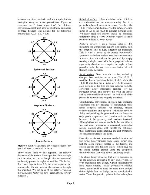
etween best form, aspheric, and atoric optimization<br />
strategies using an actual prescription. Figure 6<br />
compares the ‘relative asphericity’ (an abstract<br />
correction concept used here for illustrative purposes)<br />
<strong>of</strong> three different lens designs for the following<br />
prescription: +2.00 -1.00 × 090.<br />
0.0<br />
-4.0<br />
-1.5<br />
0.0<br />
0.0<br />
Spherical Surface<br />
-4.0<br />
0.0<br />
0.0 0.0<br />
-4.0<br />
0.0<br />
Aspheric Surface<br />
-4.0<br />
-4.0<br />
-4.0 -4.0<br />
-2.5<br />
-4.0<br />
-2.5<br />
-2.5 -2.5<br />
-4.0<br />
0.0<br />
-4.0<br />
-1.5<br />
<strong>Atoric</strong> Surface<br />
Figure 6. Relative asphericity (or correction factors) for<br />
spherical, aspheric, and atoric surfaces.<br />
These values more or less represent the relative<br />
departure <strong>of</strong> the surface from a perfect circle through<br />
each meridian, and can be thought <strong>of</strong> as the amount <strong>of</strong><br />
asphericity present through that meridian. The further<br />
this value departs from 0.0, the more aspheric (or<br />
non-circular) the curvature <strong>of</strong> the surface is through<br />
that meridian. We can think <strong>of</strong> this relative value as<br />
the ‘correction factor’ for now (again, strictly for our<br />
purposes).<br />
Spherical surface. It has a relative value <strong>of</strong> 0.0 in<br />
every direction (or meridian)—meaning that it is<br />
perfectly spherical in every direction. Therefore, the<br />
+2.00 D sphere meridian receives the same correction<br />
factor <strong>of</strong> 0.0 as the +1.00 D cylinder meridian does.<br />
We know these two powers should be optimized<br />
differently, since a +1.00 D power requires a flatter<br />
base curve than a +2.00 D power.<br />
Aspheric surface. It has a relative value <strong>of</strong> -4.0,<br />
indicating the aspheric lens departs significantly from<br />
the spherical lens in every direction (or meridian).<br />
This is what is meant by the phrase ‘rotationallysymmetric’—the<br />
lens surface have the same curvature<br />
in every direction, and can be produced by simply<br />
rotating a single curve with the appropriate relative<br />
asphericity about an axis. Again, the aspheric lens<br />
provides only the one correction factor <strong>of</strong> -4.0<br />
through every meridian.<br />
<strong>Atoric</strong> surface. Note how the relative asphericity<br />
changes from meridian to meridian. The +2.00 D<br />
meridian has a correction factor <strong>of</strong> -4.0, while the<br />
+1.00 D meridian has a factor <strong>of</strong> -1.5. In essence,<br />
each meridian <strong>of</strong> the lens has been adjusted with the<br />
correction factor specifically required for that<br />
particular power. This ensures that both the sphere<br />
and cylinder meridional powers—as well as all <strong>of</strong> the<br />
powers in between—are properly optimized.<br />
Unfortunately, conventional spectacle lens surfacing<br />
equipment was not designed to manufacture these<br />
rather complex surfaces. For instance, modern<br />
cylinder machines and lap tools—which are used for<br />
fining and polishing the generated lens surface—can<br />
only produce spherical and circular toric surfaces<br />
because <strong>of</strong> the geometry and motions involved.<br />
Although there are systems available that use either a<br />
‘cut and coat’ process or a numerically-controlled<br />
milling machine along with flexible-pad polishing,<br />
these systems are quite expensive and cost-prohibitive<br />
for most laboratories at this point.<br />
Currently, most atoric lenses are available in either <strong>of</strong><br />
two forms: factory finished stock lenses—which have<br />
had the atoric surface molded at the factory, and<br />
custom-ground semi-finished lenses—which have had<br />
the atoric surface ground using the equipment<br />
described above (typically also at the factory level).<br />
The atoric design strategies that we’ve discussed so<br />
far are generally applicable to any single vision (or<br />
even multifocal) lens design. Certain manufacturers<br />
have begun <strong>of</strong>fering ‘atoric’ progressive addition<br />
lenses, but it should be noted that these atoric designs<br />
differ slightly from the design that we have looked at<br />
so far. These designs still optimize for both the sphere<br />
Page 3