SCS.1d - Stanton
SCS.1d - Stanton
SCS.1d - Stanton

Create successful ePaper yourself
Turn your PDF publications into a flip-book with our unique Google optimized e-Paper software.
Encoder Section<br />
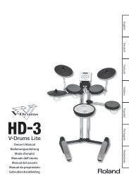
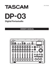
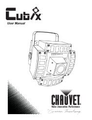
3.2 Encoder Section<br />
This section consists of four rotary push encoders, each with an LED<br />
encoder ring to indicate the value of the encoder, and an LCD “scribble<br />
strip” that can be used to indicate the functionality of each encoder.<br />
Encoders are used to control variable parameters such as effect levels.<br />
Encoders do not physically stop when you turn them; instead the LED<br />
encoder rings indicate the position of the control you are adjusting.<br />
(Figure 3.2)<br />
Figure 3.2<br />
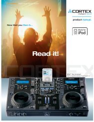
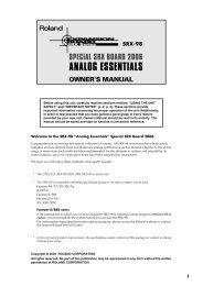
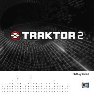
3.3 Trigger Section<br />
The trigger section consists of four velocity sensitive pads, four LCD<br />
“scribble strips”, and seven clicking switches.<br />
Each pad, switch and screen is backlit by multicolor (red, green, orange)<br />
LED’s. The velocity sensitive pads and switches are typically assigned to<br />
trigger actions such a playing cue points, moving loops or killing<br />
frequencies. The LCD “scribble strips” will display functionality and status<br />
depending on the preset.(Figure 3.3)<br />
Figure 3.3<br />
7