Pacific Coal provided data for typical operating parameters used in ...
Pacific Coal provided data for typical operating parameters used in ...
Pacific Coal provided data for typical operating parameters used in ...

You also want an ePaper? Increase the reach of your titles
YUMPU automatically turns print PDFs into web optimized ePapers that Google loves.
<strong>Pacific</strong> <strong>Coal</strong> <strong>provided</strong> <strong>data</strong> <strong>for</strong> <strong>typical</strong> <strong>operat<strong>in</strong>g</strong> <strong>parameters</strong> <strong>used</strong> <strong>in</strong> dragl<strong>in</strong>e operation.<br />
The problem <strong>for</strong> the Study Group was to <strong>in</strong>vestigate whether an optimal<br />
model of dragl<strong>in</strong>e operation could be developed.<br />
The Study Group modelled the sequence of operations <strong>for</strong> a <strong>typical</strong> surface m<strong>in</strong><strong>in</strong>g<br />
strip. Overall, a simulation approach seems necessary to fully represent the<br />
dragl<strong>in</strong>e operation. Some aspects of the operations that are amenable to optimisation<br />
are described <strong>in</strong> this report.<br />
In Australia, approximately 12% of total <strong>for</strong>eign earn<strong>in</strong>gs come from export<strong>in</strong>g coal.<br />
The walk<strong>in</strong>g dragl<strong>in</strong>e is <strong>used</strong> extensively to remove overburden <strong>in</strong> the surface m<strong>in</strong><strong>in</strong>g of<br />
coal <strong>in</strong> Australia. A total of around 60 dragl<strong>in</strong>e mach<strong>in</strong>es are <strong>used</strong> to strip overburden<br />
from above about 35% of the coal m<strong>in</strong>ed <strong>in</strong> Australia.<br />
It is estimated that an improvement of 1% <strong>in</strong> the efficiency of dragl<strong>in</strong>e operation<br />
would contribute an extra $35 million to Australia's export earn<strong>in</strong>gs.<br />
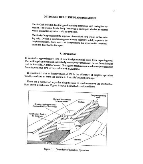
There are a number of ways that dragl<strong>in</strong>es can be <strong>used</strong> to remove the overburden<br />
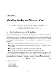
from above a coal seam. Figure 1 shows the method considered here.<br />
Dragf<strong>in</strong>e <strong>operat<strong>in</strong>g</strong><br />
level
A given dig cycle <strong>in</strong> the process of m<strong>in</strong><strong>in</strong>g the coal <strong>in</strong>volves the excavation of three<br />
blocks. The overburden and bridge blocks are removed to expose the next section<br />
of coal. S<strong>in</strong>ce the bridge is built us<strong>in</strong>g material from the previous cycle, its removal<br />
<strong>in</strong>volves rehandl<strong>in</strong>g the overburden. The highwall bench block is removed to prepare<br />
the <strong>operat<strong>in</strong>g</strong> bench level <strong>for</strong> the dragl<strong>in</strong>e to use dur<strong>in</strong>g the next cycle.<br />
Some of the material removed dur<strong>in</strong>g the excavation is <strong>used</strong> to build a new bridge<br />
and the rest is dumped onto the spoil pile.<br />
At the end of the cycle the situation will be as <strong>in</strong> figure 1 but shifted back by the<br />
excavation length along the strip.<br />
The general sequence of operations dur<strong>in</strong>g the cycle <strong>for</strong> the excavation of the highwall,<br />
overburden and bridge blocks is as follows:<br />
Once the new bench region is excavated the drag l<strong>in</strong>e beg<strong>in</strong>s to remove the overburden<br />
adjacent to the highwall. As this cut deepens the dragl<strong>in</strong>e steps <strong>for</strong>ward to<br />
reach the lower material, end<strong>in</strong>g at position 2.<br />
Dur<strong>in</strong>g the <strong>in</strong>itial cut <strong>in</strong>to the overburden the dragl<strong>in</strong>e moves <strong>in</strong> l<strong>in</strong>e with the highwall<br />
and digs a narrow trench down to the coal. This <strong>in</strong>itial excavation gives a<br />
clean high wall face and is called the keycut.<br />
At some stage the new bridge will be f<strong>in</strong>ished.<br />
extend the spoil pile.<br />
The material is then dumped to<br />
2. Once the keycut is complete the dragl<strong>in</strong>e moves to posi tion 3 and beg<strong>in</strong>s to remove<br />
the next section of overburden, stepp<strong>in</strong>g <strong>for</strong>ward towards position 4 as the depth<br />
of the dig <strong>in</strong>creases. When the coal seam is reached and exposed the dragl<strong>in</strong>e<br />
moves to position 5 and repeats this process <strong>for</strong> the next section of overburden.<br />
3. This process is repeated until all the material <strong>in</strong> the overburden and bridge blocks<br />
has been excavated and dumped onto the spoil pile.<br />
The dragl<strong>in</strong>e will move out onto the new bridge dur<strong>in</strong>g the f<strong>in</strong>al excavation of the<br />
old bridge.<br />
4. Once all the material has been excavated the dragl<strong>in</strong>e moves off the new bridge<br />
and takes up position ready <strong>for</strong> the next cycle. This f<strong>in</strong>al position is at a distance<br />
equal to the length of the excavation along the strip beh<strong>in</strong>d the start<strong>in</strong>g position.
Given the depth of the coal below the surlace and the thickness of the coal<br />
seam, and the overburden geology, exam<strong>in</strong>e what methods are available to<br />
optimise overall perlormance or aspects of the per<strong>for</strong>mance.<br />
In order to <strong>for</strong>mulate the problem satisfactorily, we need to look <strong>in</strong> more detail at the<br />
particular operations <strong>in</strong>volved <strong>in</strong> excavat<strong>in</strong>g the overburden.<br />
As a first step we need to split the blocks that are to be excavated <strong>in</strong>to sub-blocks<br />
of suitable size. The material excavated from each of these sub-blocks will be dumped<br />
onto a correspond<strong>in</strong>g sub-block on either the new bridge or the spoil pile.<br />
We will use the notation O-D to denote the Orig<strong>in</strong>-Dest<strong>in</strong>ation<br />
that will be excavated and filled dur<strong>in</strong>g the cycle.<br />
pairs of sub-blocks<br />
The basic operations <strong>in</strong> the excavation of a given sub-block are to fill the bucket, to<br />
hoist it vertically upwards and to sw<strong>in</strong>g over to a position above the associated dest<strong>in</strong>ation<br />
sub-block. Once the contents of the bucket are dumped, the return operations are<br />
to sw<strong>in</strong>g back and lower the bucket onto the orig<strong>in</strong> sub-block and repeat the process.<br />
For the present study we assume that the bucket fill<strong>in</strong>g time and the quantity of<br />
material picked up by the bucket are <strong>in</strong>dependent of the sub-block location except <strong>for</strong><br />
the fact that the dragl<strong>in</strong>e operates at 70% efficiency when digg<strong>in</strong>g material above the<br />
<strong>operat<strong>in</strong>g</strong> level.<br />
For a given O-D pair, the time required to hoist, sw<strong>in</strong>g over, sw<strong>in</strong>g back and lower<br />
the bucket depends on:<br />
a) The vertical distance through which the bucket must be moved to allow a clear<br />
sw<strong>in</strong>g from above the 0 sub-block to above the D sub-block. This distance will<br />
depend on the relative heights of the 0 and D sub-blocks and on the <strong>operat<strong>in</strong>g</strong> level<br />
if it is necessary to lift the bucket clear of unexcavated sections of the overburden<br />
and bridge blocks.<br />
b) The angle through which the bucket is moved. This will depend on the relative<br />
horizontal co-ord<strong>in</strong>ates of the O-D pair and the dragl<strong>in</strong>e position.<br />
The f<strong>in</strong>al factor affect<strong>in</strong>g excavation time is the time needed to move the dragl<strong>in</strong>e between<br />
the dig positions associated with successive O-D pairs.
DdowlI=45m<br />
Dup = 45.7m<br />
D reach = 82m<br />
Y ob =40m<br />
Y coal = 10m<br />
a = 76°<br />
J3 = 38°<br />
Y = 60°<br />
Vb = 46m 3<br />
v = 200 m h- 1<br />
Sl = 1.25<br />
S2 = 1.30<br />
td = 15 see<br />
Maximum dragl<strong>in</strong>e digg<strong>in</strong>g depth<br />
Maximum dragl<strong>in</strong>e dump height<br />
Effective dragl<strong>in</strong>e reach<br />
Overburden depth<br />
Depth of coal seam<br />
Highwall bench angle<br />
Spoil repose angle<br />
Keycut and work<strong>in</strong>g face angles<br />
Volume of material <strong>in</strong> the bucket<br />
Walk<strong>in</strong>g speed of the dragl<strong>in</strong>e<br />
Swell factor after blast<strong>in</strong>g the overburden<br />
Swell factor after dump<strong>in</strong>g material to the spoil pile<br />
Time to fill the dragl<strong>in</strong>e bucket<br />
Let N be the total number of 0 sub-blocks.<br />
There are N correspond<strong>in</strong>g D sub-blocks.<br />
An 0 sub-block is represented by j.<br />
j 1, ... ,M are the 0 sub-blocks <strong>in</strong> the highwall bench blocks.<br />
j = M + 1, ,P are the 0 sub-blocks <strong>in</strong> the overburden block.<br />
j = P + 1, ,N are the 0 sub-blocks <strong>in</strong> the bridge.<br />
V j is the volume of the jth 0 sub-block.<br />
d j is the distance from dragl<strong>in</strong>e positionj to position (j+ 1).<br />
The digg<strong>in</strong>g efficiency is e = 1 when digg<strong>in</strong>g below the <strong>operat<strong>in</strong>g</strong> level and e = 0.7<br />
when digg<strong>in</strong>g above the <strong>operat<strong>in</strong>g</strong> level.
hoist time<br />
lower<strong>in</strong>g time<br />
tll = 0.3715h + 2.9923<br />
see<br />
t[ = 0.2474h - 0.0264 see<br />
For a horizontal<br />
given by<br />
sw<strong>in</strong>g angle 9 degrees, the sw<strong>in</strong>g <strong>for</strong>ward and sw<strong>in</strong>g back times are<br />
sw<strong>in</strong>g <strong>for</strong>ward time<br />
sw<strong>in</strong>g back time<br />
tf = 0.11889 + 7.4764<br />
tb = 0.11779 +6.4036<br />
see<br />
see<br />
The basic problem <strong>in</strong> optimis<strong>in</strong>g the excavation process is to f<strong>in</strong>d a one to one map<br />
between the 0 and D sub-blocks where the 3-d geometry of the mapp<strong>in</strong>g <strong>in</strong>corporates<br />
a dragl<strong>in</strong>e position <strong>for</strong> each O-D pair. For the moment let the map be def<strong>in</strong>ed <strong>in</strong> terms<br />
of h and 9. These values can be def<strong>in</strong>ed <strong>in</strong> terms of a suitably chosen co-ord<strong>in</strong>ate<br />
system such as that <strong>in</strong> figure 5.<br />
Once the bucket is filled, the 'hoist, sw<strong>in</strong>g over, sw<strong>in</strong>g back, lower' operation beg<strong>in</strong>s.<br />
Dur<strong>in</strong>g this cycle different motors are <strong>used</strong> to hoist and sw<strong>in</strong>g the bucket. The vertical<br />
and horizontal movements are <strong>in</strong>dependent so that <strong>for</strong> a given 'hoist, sw<strong>in</strong>g <strong>for</strong>ward'<br />
operation the time to move from an <strong>in</strong>itial position I to a f<strong>in</strong>al position F, separated by<br />
a height h and angle 9 is given by<br />
This time is said to be 'hoist dependent'<br />
tf is greater.<br />
or 'sw<strong>in</strong>g dependent' based on which of tll and<br />
For a given O-D pair, there may be a number of 'hoist, sw<strong>in</strong>g <strong>for</strong>ward' and 'sw<strong>in</strong>g<br />
back, lower' steps. For example, <strong>in</strong> the excavation of the keycut (region 1 <strong>in</strong> figure 3)<br />
the bucket must clear the outer comer of the keycut pit be<strong>for</strong>e it can be moved to the<br />
dump<strong>in</strong>g position.<br />
If there are K such steps needed to move the bucket from the orig<strong>in</strong> to the dest<strong>in</strong>ation<br />
of a given O-D pair then the total time required <strong>for</strong> the 'hoist sw<strong>in</strong>g <strong>for</strong>ward' and 'sw<strong>in</strong>g<br />
back, lower' cycle is<br />
K<br />
tOD= i:)tIFt<br />
.e..!<br />
+ tFIt)
The time needed to excavate the jth 0 sub-block, and hence the jth O-D pair, is given<br />
by<br />
1J =<br />
Sl V.<br />
Vb} (tJe + tOD)<br />
0.7, j = 1 ... M<br />
where e = { 1.0,<br />
J=<br />
. M + 1 ... N<br />
_ { 1.25, j = 1 '" p<br />
, Sl - 1.00, . PIN J= + ..,<br />
and V/V b is the number of cycles of the "fill, hoist, sw<strong>in</strong>g <strong>for</strong>ward, sw<strong>in</strong>g back, lower"<br />
bucket movement sequence <strong>for</strong> volume Vj.<br />
N N d.<br />
T=2:1J+2:-2<br />
j=l j=l v<br />
Note that at this stage we still have to set up a method <strong>for</strong> calculat<strong>in</strong>g h j , e and d j • We<br />
can do this by choos<strong>in</strong>g a suitable set of axes and then l<strong>in</strong>k<strong>in</strong>g the centres of the 0 and<br />
D sub-blocks via an arbitrary (dragl<strong>in</strong>e) position on the <strong>operat<strong>in</strong>g</strong> bench.<br />
Dur<strong>in</strong>g this process we need to consider a way of stat<strong>in</strong>g the comb<strong>in</strong>atorial problem<br />
aris<strong>in</strong>g from the mapp<strong>in</strong>g between the 0 and D sub-blocks that will allow us to m<strong>in</strong>imise<br />
the value of T.<br />
There are constra<strong>in</strong>ts associated with the sequenc<strong>in</strong>g of the O-D pairs, with the dragl<strong>in</strong>e<br />
dimensions and with the volumes of overburden excavated.<br />
When sett<strong>in</strong>g up the sequence of O-D mapped pairs we need to consider the follow<strong>in</strong>g<br />
po<strong>in</strong>ts:<br />
• The horizontal distance between 0 sub-blocks and possible D sub-blocks<br />
exceed twice the dragl<strong>in</strong>e reach.<br />
cannot<br />
• When excavat<strong>in</strong>g the overburden and bridge we cannot excavate an 0 sub-block<br />
until the one above it has been removed.<br />
• When build<strong>in</strong>g the spoil pile we cannot fill a D sub-block until the one below it<br />
has been completed.<br />
These po<strong>in</strong>ts relate obviously to the general digg<strong>in</strong>g sequence <strong>in</strong> which, if the dragl<strong>in</strong>e<br />
starts <strong>in</strong> position 1 as <strong>in</strong> figure 1 and moves out onto the bridge, the spoil dump locations
The second set of constra<strong>in</strong>ts relates to the strip geometry and the dragl<strong>in</strong>e geometry.<br />
To write these constra<strong>in</strong>ts we need to refer to figure 2.<br />
Elevation (m)<br />
160<br />
140<br />
120<br />
100<br />
80<br />
60<br />
40<br />
20<br />
o<br />
o 40<br />
Distance (m)<br />
160<br />
140<br />
120<br />
100<br />
80<br />
60<br />
40<br />
20<br />
o<br />
Figure 2:<br />
Dragl<strong>in</strong>e Range Diagram<br />
We have a volume constra<strong>in</strong>t which, assum<strong>in</strong>g that the volume of material <strong>used</strong> to build<br />
the new bridge is equal to the volume removed <strong>in</strong> excavat<strong>in</strong>g the old bridge, we can<br />
write as<br />
where VH is the volume of the highwall bench, Vo is the volume of the overburden, Vs<br />
is the volume of the spoil pile and Sz is the swell factor relat<strong>in</strong>g the prime volumes to<br />
the volume <strong>in</strong> the spoil pile.<br />
• The horizontal distance from 5 metres be<strong>for</strong>e the edge of the bridge to the spoil<br />
pile peak cannot exceed the dragl<strong>in</strong>e reach. The 5 metres is a safety factor, the<br />
dragl<strong>in</strong>e cannot be moved any closer to the edge of the bridge than this distance.<br />
• The vertical distance from the <strong>operat<strong>in</strong>g</strong> level to the spoil pile peak cannot exceed<br />
the dragl<strong>in</strong>e maximum dump height.
• The vertical distance from the <strong>operat<strong>in</strong>g</strong> level to the top of the highwall bench<br />
block cannot exceed <strong>typical</strong>ly 30 metres.<br />
• The vertical distance from the <strong>operat<strong>in</strong>g</strong> level to the bottom of the coal seam cannot<br />
exceed the dragl<strong>in</strong>e maximum digg<strong>in</strong>g depth. Here we are assum<strong>in</strong>g that the coal<br />
seam is horizontal.<br />
The fonnulation of these constra<strong>in</strong>ts is straight<strong>for</strong>ward once we have chosen a coord<strong>in</strong>ate<br />
system to suitably describe the dragl<strong>in</strong>e and sub-block locations. They are<br />
given as equations 14 and 15.<br />
Figure 3 shows the division of the overburden material <strong>in</strong>to <strong>typical</strong> sub-blocks. The 0<br />
sub-blocks are shown <strong>in</strong> figure 3 (a) and the D sub-blocks <strong>in</strong> figure 3 (b). A view from<br />
above is given <strong>in</strong> figure 4.<br />
The blocks are excavated <strong>in</strong> order from 1 to 4. The orig<strong>in</strong> of the jth sub-block is given<br />
by OJ which is taken as the centre of mass of the orig<strong>in</strong> sub-block. The correspond<strong>in</strong>g<br />
dest<strong>in</strong>ation is given by D j • The locations of the D j are the po<strong>in</strong>ts at which the material<br />
is released so that the spoil pile sub-blocks will build naturally at the repose angle 13.<br />
The location of the dragl<strong>in</strong>e <strong>for</strong> the jth O-D pair is given by P j •<br />
Note that, <strong>for</strong> demonstration purposes, we have assumed that the bridge is built from<br />
the keycut (region 1) and from the material above the <strong>operat<strong>in</strong>g</strong> level (region 2). We<br />
also assume that region 2 is excavated from two dragl<strong>in</strong>e positions. The first position is<br />
the same as that <strong>for</strong> the keycut, <strong>in</strong> this position we have only to move spoil material to<br />
the edge of the highwall. The rest of region 2 must be excavated from a new position<br />
so that we can reach position D 2b at the edge of the bridge.<br />
Referr<strong>in</strong>g to figure 4, we can see that there is no po<strong>in</strong>t <strong>in</strong> mov<strong>in</strong>g the dragl<strong>in</strong>e position<br />
P j closer to the dest<strong>in</strong>ation location D j than the length given by the effective dragl<strong>in</strong>e<br />
reach, s<strong>in</strong>ce this will only <strong>in</strong>crease the sw<strong>in</strong>g angle <strong>for</strong> a given O-D pair.<br />
This means that we can fix the position of Pj, <strong>in</strong> the direction perpendicular to the<br />
strip, from the location of the correspond<strong>in</strong>g dest<strong>in</strong>ation D j • Further, we can calculate<br />
the location of a particular dest<strong>in</strong>ation from the geometry shown <strong>in</strong> figures 3 and 4,<br />
together with the parameter values given <strong>in</strong> Table 1.
®<br />
r-----------<br />
I<br />
I D1.D2D<br />
1 """"I- - - - - - _1- - - -<br />
I<br />
\<br />
'~~llliljil~i:lllll:~ll:l:ll!Mlll:;li:l::j!ji: CD
Given a set of <strong>parameters</strong> as <strong>in</strong> Table 1, the O-D geometry shown <strong>in</strong> figures 3 and 4,<br />
and equations 5 to 9, we can develop a simulation model of the dragl<strong>in</strong>e operation. We<br />
need to specify <strong>in</strong> addition, the width at the bottom of region 1 (the keycut) and the<br />
width of region 3.<br />
Us<strong>in</strong>g this <strong>data</strong> we can calculate the orig<strong>in</strong> positions, the size of the bridge and the<br />
locations of the sub-block dest<strong>in</strong>ation positions. We can then calculate the excavation<br />
times needed <strong>for</strong> the different O-D pairs.<br />
It is possible to specify the system completely except <strong>for</strong> the dragl<strong>in</strong>e position coord<strong>in</strong>ates<br />
<strong>in</strong> the direction along the strip. Consequently, a useful simulation model can<br />
be developed <strong>in</strong> which a user could study a series of 'what if' scenarios <strong>in</strong> which the<br />
dragl<strong>in</strong>e positions can be specified with a s<strong>in</strong>gle variable.<br />
Such a simulation model can be made more accurate by divid<strong>in</strong>g the overburden <strong>in</strong>to<br />
smaller regions.<br />
At present a prototype model, <strong>in</strong> which the regions 1-4 have each been divided <strong>in</strong>to<br />
three horizontal layers, is under development. This prototype model is giv<strong>in</strong>g realistic<br />
output results at the current stage of verification.<br />
In this section we develop <strong>for</strong>mulae to f<strong>in</strong>d the optimum <strong>operat<strong>in</strong>g</strong> level Yb and pit width<br />
X pil <strong>for</strong> the dragl<strong>in</strong>e. We use figure 5 as reference.<br />
Yco al<br />
a ::~~~:l~l~l~:jj~~~:~lj!:jj:~!:::~:~~!::~~:~~!~j~:!:j:!!:~!::~j~~::::;!~~:j::::::j~:~:~:::::~j~:l:l:::~::jt<br />
(0,0)<br />
-.••~-- Xpil -----1-""--- Xpil
From figure 5 we have Y s = 0.5 Xpit tan P and substitut<strong>in</strong>g <strong>for</strong> Y s <strong>in</strong> the volume<br />
balance equation: (expanded overburden volume) = (spoil pile volume) which can be<br />
written<br />
then from xp = Xpit +yp/ tan p we have<br />
1<br />
YP = sZYob + "4Xpit tan p<br />
The values of xp and YP depend on the dragl<strong>in</strong>e dimensions and the location (xp, Yp) of<br />
the spoil pile peak:. We have from Xb = xp-D reach (where D reach <strong>in</strong>cludes a safety factor<br />
represent<strong>in</strong>g the distance that the dragl<strong>in</strong>e must rema<strong>in</strong> from the edge of the bridge)<br />
Xb<br />
sZYob<br />
= 1.25X pit + ---a -D reach<br />
tanp<br />
Note that if Xb S Xd = Xpit - ~ then we do not need a bridge.<br />
tan a<br />
The <strong>operat<strong>in</strong>g</strong> level Yb is one of the variables we wish to f<strong>in</strong>d, it is constra<strong>in</strong>ed by the<br />
dragl<strong>in</strong>e dimensions so that:<br />
(14)<br />
(IS)
For the particular model under consideration, the total excavation time will be <strong>in</strong>fluenced<br />
by:<br />
a) the cross sectional area A b of the bridge, if one is built,<br />
b) the fact that digg<strong>in</strong>g efficiency is reduced to e = 70% when remov<strong>in</strong>g overburden<br />
from above the <strong>operat<strong>in</strong>g</strong> level Yb.<br />
Assum<strong>in</strong>g that <strong>for</strong> an efficient digg<strong>in</strong>g operation, excavation times will depend on the<br />
volumes (and here, on cross sectional areas) of material shifted. we can write an equation<br />
<strong>for</strong> the excavation time T. The equation <strong>for</strong> T will conta<strong>in</strong> a term related to excavat<strong>in</strong>g<br />
the bridge and a term related to <strong>operat<strong>in</strong>g</strong> below the surface level.<br />
For purposes of comparison we are <strong>in</strong>terested <strong>in</strong> a normalised measure of excavation<br />
time. We will use T/X pit • the excavation time per unit (pit) width. This is proportional to<br />
the excavation time to uncover a fixed amount of coal and hence maximum productivity<br />
is obta<strong>in</strong>ed by m<strong>in</strong>imis<strong>in</strong>g T/X pit •<br />
From<br />
and our aim is to m<strong>in</strong>imise the right hand side of equation 18 with respect to X pit<br />
Yb.<br />
The effect of <strong>operat<strong>in</strong>g</strong> level on excavation productivity<br />
Figure 6 shows the relationship between excavation productivity and <strong>operat<strong>in</strong>g</strong> level<br />
<strong>for</strong> a number of different pit widths.<br />
The curves <strong>for</strong> X pit = 60-100 represent cases where we need to build a bridge. For<br />
the curve X pit = 20 no bridge is needed. We will look at this factor <strong>in</strong> more detail <strong>in</strong> the<br />
next section.<br />
The diagram shows that. <strong>for</strong> a given pit width it is. <strong>in</strong> general. possible to f<strong>in</strong>d an<br />
<strong>operat<strong>in</strong>g</strong> level that maximises the productivity (m<strong>in</strong>imises the excavation time per unit<br />
width) and that the optimal productivity is greater <strong>for</strong> larger pit widths.<br />
and
We f<strong>in</strong>d the value yt <strong>for</strong> which this optimum occurs by us<strong>in</strong>g (11)-(17) to write the<br />
equation <strong>for</strong> T/X pit <strong>in</strong> terms of Yb, X pit and known <strong>parameters</strong>. Then, differentiat<strong>in</strong>g (18)<br />
with respect to Yb gives:<br />
o(T/X pit ) = ! + [1 _ !]+ _1_ [SzYob _ !D<br />
reach<br />
+ ..2'..!!- + ~] (19)<br />
0Yb 8 e X pit 2 tanf3 2 tan a 2 tanf3<br />
oZ(T/X pit ) = _1_ [_1_ + _1_] > 0 so we have a m<strong>in</strong>imum.<br />
oY/ Xpit tan a 2 tan f3<br />
1 1<br />
kz=--+--<br />
tan a 2tanf3<br />
1 1<br />
k 3 = - +(1--)<br />
8 e
The effect of pit width on excavation productivity<br />
Figure 7 shows the relationship between excavation productivity and pit width <strong>for</strong> a<br />
number of different <strong>operat<strong>in</strong>g</strong> levels.<br />
X pil<br />
(m)<br />
Figure 7:<br />
Dig time per unit width vs pit width<br />
For fixed values of Yb, (18) shows some <strong>in</strong>terest<strong>in</strong>g properties.<br />
If Yb > k 1 (1 + Jl + 2k 2 tan (3)/2k 2 , which we calculate below and which corresponds<br />
to Xb > Xd , then the function behaves as shown by the CUIVes<strong>for</strong> Yb = 25-50. Physically<br />
these values of Yb correspond to situations where we need to build a bridge <strong>in</strong> order to<br />
reach the horiwntal peak: of the spoil pile. The productivity <strong>in</strong>creases with pit width but<br />
with a law of dim<strong>in</strong>ish<strong>in</strong>g return as the width <strong>in</strong>creases. We should use the maximum<br />
pit width possible.<br />
If Yb is less than the value given <strong>in</strong> the previous paragraph, then the function behaves<br />
as shown by the CUIVe<strong>for</strong> Yb = 15. In this case (18) is not physically relevant. It gives a<br />
solution correspond<strong>in</strong>g to a situation <strong>in</strong> which no bridge is needed and an unnecessary<br />
volume of material is simply moved along the pit.<br />
Differentiat<strong>in</strong>g<br />
(18) with respect to X pil gives<br />
ax . = 2X2 (k1Yb - k2Yb) + 2 tan P("l - (Xpi,/4) )<br />
pll<br />
pll<br />
a(T/Xpil) 1 [ 2 1 n ,2 2 ]<br />
a 2 (T/Xpil) 1 [ 2 1,2 n]<br />
aX2. = - X3. (k1Yb - k2Yb) + 21'1 tan P<br />
pll<br />
pll<br />
The second derivative switches from negative to positive, correspond<strong>in</strong>g<br />
to the change
<strong>in</strong> behaviour shown by the difference between the curves <strong>for</strong> Yb = 15 and Yb = 25 <strong>in</strong><br />
figure 7, when<br />
k 1 (1 + }1 + 2k 2 tan /3)<br />
Yb = 2k 2<br />
For this value of Yb the outer top of the bridge co<strong>in</strong>cides with the edge of the highwall<br />
(i.e. Xb = Xd).<br />
For Yb greater than this value the second derivative will be positive and we obta<strong>in</strong><br />
the behaviour shown by the curves Yb = 25-50 <strong>in</strong> figure 7.<br />
If Yb is less than this value then (18) is not physically relevant s<strong>in</strong>ce we do not need a<br />
bridge. We remove the area term A b from (18) and note, obviously, that the productivity<br />
<strong>in</strong>creases as we <strong>in</strong>crease Yb and reduce the amount of material removed from above the<br />
<strong>operat<strong>in</strong>g</strong> level.<br />
Optimis<strong>in</strong>g productivity us<strong>in</strong>g non l<strong>in</strong>ear programm<strong>in</strong>g<br />
The above results were confirmed by us<strong>in</strong>g the MINOS Non L<strong>in</strong>ear Programm<strong>in</strong>g optimiser<br />
to m<strong>in</strong>imise (18) subject to the constra<strong>in</strong>ts of (14,15) and with the lower bound<br />
on Yb set by (23). The program was run with different upper bounds (but all less than<br />
90 metres) on X pit '<br />
In all cases the optimisation drove the pit width to its upper bound and returned an<br />
optimum value <strong>for</strong> Yb as given by substitut<strong>in</strong>g the upper bound of the pit width <strong>in</strong>to<br />
(20).<br />
Conclusions<br />
The above discussion assumes that we will not triple handle the overburden material.<br />
This means that we are restrict<strong>in</strong>g the maximum pit width to be less than the maximum<br />
effective reach of the dragl<strong>in</strong>e.<br />
In this situation the results <strong>in</strong>dicate that the most effective operation is obta<strong>in</strong>ed by<br />
choos<strong>in</strong>g the maximum pit width possible and then calculat<strong>in</strong>g the <strong>operat<strong>in</strong>g</strong> level us<strong>in</strong>g<br />
* 1 k2<br />
Yb = - k (k3Xpit - 2" )<br />
1
7. Solv<strong>in</strong>g the comb<strong>in</strong>atorial part of the<br />
problem with Dynamic Programm<strong>in</strong>g<br />
I<br />
I<br />
I<br />
I<br />
I<br />
I y"<br />
I<br />
P"<br />
I<br />
I<br />
I<br />
I<br />
I<br />
--.2 Sl S<br />
____ -- __ S3 -s<br />
4<br />
______________ ~_S_,,__ .- Sll+l<br />
If we know the excavation rate as a function of location across the overburden block<br />
then we can use Dynamic Programm<strong>in</strong>g to determ<strong>in</strong>e an optimal way of divid<strong>in</strong>g the<br />
overburden <strong>in</strong>to sub-blocks correspond<strong>in</strong>g to the different dragl<strong>in</strong>e excavation positions.<br />
The DP procedure is applied <strong>in</strong> the context of the geometry shown <strong>in</strong> figure 8. We<br />
divide the overburden <strong>in</strong>to k excavation positions P 1 ,P 2 , '" ,P k • With reference to<br />
figure 3 on page 9, once we have specified the width of the base of the keycut and the<br />
total width of region 3 (which we may divide <strong>in</strong>to sub-blocks as here), the first and last<br />
positions are given by the overall geometry.<br />
Let s" be the distance to the orig<strong>in</strong> (bottom left corner) of block n - 1, then<br />
with Sl = O.<br />
1\-1<br />
S,,= LYi , n=2,3, ... ,k<br />
i=l<br />
Also, let f,,(s,,) denote the optimal (m<strong>in</strong>imal) time required to remove the rema<strong>in</strong><strong>in</strong>g<br />
overburden, given that after remov<strong>in</strong>g n - 1 blocks we are <strong>in</strong> position s". Then<br />
fk+1(Sk+l) = 0, and the optimal time to move the entire cut is given by f1(0).<br />
We can show that the follow<strong>in</strong>g functional equation holds.<br />
where<br />
f,,(s,,) = m<strong>in</strong> {T(s",y,,) + f"+l(S" +y,,)}, 1 ~ n ~ k , S" E S"<br />
y.eD(s.)<br />
D(s,,) = the set of feasible values of y" given that we are <strong>in</strong>:<br />
S" = the set of (discrete) feasible values of s".<br />
T(s", y,,) = the time to move the nth sub-block to the spoil pile.<br />
(25) can be solved rapidly - assum<strong>in</strong>g that the function T can be evaluated rapidly.<br />
This <strong>for</strong>mulation takes advantage of the fact that the model is "separable" <strong>in</strong> a dynamic<br />
programm<strong>in</strong>g sense (Sniedovich, 1992).
8. Sequenc<strong>in</strong>g the excavation from<br />
the keycut and highwall blocks<br />
In this section we consider that part of the excavation where the dragl<strong>in</strong>e operator can<br />
choose to dig from either the high wall bench block or from the keycut region. In<br />
particular, we <strong>in</strong>vestigate whether there is an optimal sequenc<strong>in</strong>g of the digg<strong>in</strong>g from<br />
these two regions that will m<strong>in</strong>imise the excavation time.<br />
By mak<strong>in</strong>g appropriate simplifications we can remove excess complexity from the<br />
problem but reta<strong>in</strong> its essential elements. Here, we look at a simplification of the<br />
operations <strong>in</strong> which we reduce the number of spatial dimensions <strong>used</strong> to describe the<br />
overburden. We assume average behaviour <strong>for</strong> two dimensions and then conduct the<br />
analysis with respect to the rema<strong>in</strong><strong>in</strong>g dimension.<br />
We reta<strong>in</strong> the s<strong>in</strong>gle dimension across the pit and assume that, <strong>for</strong> each section of<br />
the overburden (averaged down and along the pit), the times to fill, hoist and lower<br />
the bucket rema<strong>in</strong> relatively constant. We take the major variable part of the total<br />
excavation time to be the sw<strong>in</strong>g times.<br />
Figure 9 shows the simplified geometry <strong>for</strong> the sequenc<strong>in</strong>g problem.<br />
to represent the overhand block and side 'b' represents the keycut.<br />
Side 'a' is taken<br />
(ai, 1)<br />
Pz<br />
(az - ai)x(p)<br />
(b i ,-I)<br />
(bz -<br />
bi)y(p)<br />
The distances from the dragl<strong>in</strong>e path to the centre l<strong>in</strong>es of the overburden blocks can<br />
be normalised to 1 without loss of generality.
ai, a2<br />
b l , b 2<br />
Va<br />
Vb<br />
e a<br />
eb<br />
A<br />
B<br />
e<br />
the end co-ord<strong>in</strong>ates of side 'a'<br />
the end co-ord<strong>in</strong>ates of side 'b'<br />
the volume of overburden <strong>in</strong> side 'a'<br />
the volume of overburden <strong>in</strong> side 'b'<br />
the bucket fill<strong>in</strong>g efficiency when excavat<strong>in</strong>g from side 'a'<br />
the bucket fill<strong>in</strong>g efficiency when excavat<strong>in</strong>g from side 'b'<br />
the distance moved by the dragl<strong>in</strong>e <strong>in</strong> excavat<strong>in</strong>g all of side 'a'<br />
the distance moved by the dragl<strong>in</strong>e <strong>in</strong> excavat<strong>in</strong>g all of side 'b'<br />
the distance moved by the dragl<strong>in</strong>e after completely excavat<strong>in</strong>g the overburden<br />
to the spoil pile<br />
We assume that the volumes have been corrected to allow <strong>for</strong> swell<strong>in</strong>g aris<strong>in</strong>g from<br />
blast<strong>in</strong>g the overburden prior to excavation and from dump<strong>in</strong>g the overburden to the<br />
spoil pile.<br />
In practice, bucket fill<strong>in</strong>g is less efficient when digg<strong>in</strong>g the overhand block because<br />
the excavation occurs at or above the dragl<strong>in</strong>e <strong>operat<strong>in</strong>g</strong> level and it is difficult to fill<br />
the bucket. We designate digg<strong>in</strong>g efficiencies 0 S e a S 1 <strong>for</strong> side' a' and 0 S eb S 1 <strong>for</strong><br />
side 'b' to allow <strong>for</strong> this fact. A digg<strong>in</strong>g efficiency of e a = 0.8 <strong>in</strong>dicates that the bucket<br />
is filled to 80% of its capacity when digg<strong>in</strong>g from above the <strong>operat<strong>in</strong>g</strong> bench on side<br />
'a'.<br />
p the proportion of the total overburden that has been excavated so far <strong>in</strong><br />
the current cycle<br />
T}(P) the proportion of side 'a' excavated when a proportion p of the total<br />
overburden has been excavated<br />
~(P) the proportion of side 'b' excavated when a proportion p of the total<br />
overburden has been excavated<br />
(J the sw<strong>in</strong>g angle on Side 'a'.<br />
ep the sw<strong>in</strong>g angle on Side 'b'.<br />
For convenience, we ignore the 90 0 component and take the sw<strong>in</strong>g angles (J and ep to<br />
be as shown <strong>in</strong> figure 9.<br />
We <strong>in</strong>itially locate the dragl<strong>in</strong>e at position (0, 0) as shown <strong>in</strong> figure 9. The overhand<br />
overburden block is centred on the l<strong>in</strong>e (ai, 1) to (a2, 1). The keycut overburden block<br />
is centred on the l<strong>in</strong>e (b l , -1) to (b 2 , -1). The digg<strong>in</strong>g direction is constra<strong>in</strong>ed to be<br />
from (ai, 1) to (a2, 1) and from (b l ,-l) to (b2,-1).
We assume that the dragl<strong>in</strong>e position is always a fixed distance from the spoil pile<br />
dump<strong>in</strong>g po<strong>in</strong>t. This distance is set as the effective dragl<strong>in</strong>e reach so as to m<strong>in</strong>imise<br />
the angle through which the dragl<strong>in</strong>e must turn. As the overburden is excavated the<br />
dump<strong>in</strong>g po<strong>in</strong>t shifts outwards and the dragl<strong>in</strong>e moves accord<strong>in</strong>gly.<br />
Suppose that the proportion of overburden removed at some stage is p and that we<br />
<strong>in</strong>crease this to (p + i¥J) by <strong>in</strong>creas<strong>in</strong>g the proportion excavated from side 'a' from 7]<br />
to (7]+ d7]) and the proportion excavated from side 'b' from ~ to (~+d~).<br />
At this stage, the dragl<strong>in</strong>e is at position PI shown <strong>in</strong> figure 9. The excavation po<strong>in</strong>t<br />
<strong>for</strong> side 'a' is at P 2 and the excavation po<strong>in</strong>t <strong>for</strong> side 'b' is at P 3 •<br />
The volume of material removed from side 'a' is V a d7] and, assum<strong>in</strong>g a unit bucket<br />
size, the number of bucket loads <strong>in</strong>volved <strong>in</strong> this excavation is (Va/e a )d7].<br />
The angle turned through by the dragl<strong>in</strong>e <strong>in</strong> carry<strong>in</strong>g out this excavation is then given<br />
by<br />
Similarly, if we excavate a volume Vb d~ from side 'b' then the angle turned through<br />
by the dragl<strong>in</strong>e is<br />
The angle turned through <strong>in</strong> <strong>in</strong>creas<strong>in</strong>g the proportion of overburden excavated from p<br />
to (p + dp) is there<strong>for</strong>e<br />
The angles and digg<strong>in</strong>g constra<strong>in</strong>ts associated with the problem are most conveniently<br />
expressed <strong>in</strong> terms of the positions of the dragl<strong>in</strong>e and excavation po<strong>in</strong>ts on sides' a' and<br />
'b'. We there<strong>for</strong>e rewrite (28) <strong>in</strong> terms of the distances associated with these positions.<br />
For the simplified case under consideration, we specify averaged behaviour <strong>for</strong> the<br />
dimension across the strip. We assume that the dump<strong>in</strong>g position is at the outer edge<br />
of the spoil material and thus depends on the proportion of total overburden excavated.<br />
The dragl<strong>in</strong>e moves so that it is always a fixed position from the dump position. When<br />
a proportionp of the overburden has been excavated the distance moved by the dragl<strong>in</strong>e<br />
is thus Cp. This distance is made up of a displacement A 7] from digg<strong>in</strong>g side 'a' and<br />
a displacement B~ from digg<strong>in</strong>g side 'b'. At the completion of digg<strong>in</strong>g we have
We let A = kV,. and B = kV b , where k depends on the physical dimensions of the strip.<br />
The angle turned through <strong>in</strong> excavat<strong>in</strong>g a proportion Llp of the total overburden can<br />
thus be written as<br />
! (A L\TJ (J + B L\~ ep) Llp<br />
k e,. Llp eb Llp<br />
and the total angle turned through by the dragl<strong>in</strong>e as<br />
So our problem is:<br />
111(A , £l B<br />
1:-' )<br />
- -TJ u+-~ ep dp<br />
k 0 e,. eb<br />
m<strong>in</strong>imise [1 (A TJ'tan-11l+ B ;'tan- 1 v) dp<br />
10 e,. eb<br />
Il = (Cp - a1) - (a2 - a1)TJ<br />
(33)<br />
v = (Cp - b1) - (b 2 -<br />
b1)~<br />
(34)<br />
F<strong>in</strong>ally, the dragl<strong>in</strong>e digs only from overburden to spoil so TJ';;::0 and ~' ;;::0 , and from<br />
(29) and (37) we have<br />
O<br />
' A+B<br />
~TJ ~--<br />
A<br />
O<br />
):' A +B<br />
timal solution has bang-bang control, switch<strong>in</strong>g between r( = 0 , ~' = (A + B)/B and<br />
r( = (A +B)IA , ~' = O.<br />
Us<strong>in</strong>g a discrete problem <strong>for</strong>mulation, prelim<strong>in</strong>ary numerical analyses of the optimal<br />
schedules <strong>for</strong> digg<strong>in</strong>g from the two sides gave only two general excavation schedules<br />
<strong>for</strong> 1]' and ~' :<br />
Which side is excavated first depends on the geometry of the problem.<br />
is symmetric both schedules are optimal.<br />
If the problem<br />
Dynamic programm<strong>in</strong>g provides an alternative way of solv<strong>in</strong>g specific cases of this<br />
optimisation problem, and be<strong>in</strong>g a numerical technique will conveniently allow a more<br />
detailed description of the digg<strong>in</strong>g time.<br />
The state of the problem after a proportion p of overburden has been excavated is<br />
given by 1](P) so a two dimensional table with state 1](P) and stage p can be <strong>used</strong> to<br />
implement the dynamic programm<strong>in</strong>g. As we have seen above, the solution is either<br />
1]' = 0 or ~' = 0 at each small step so the dynamic programm<strong>in</strong>g needs to exam<strong>in</strong>e only<br />
these two options at each table entry. Note that multiple local optima could exist.<br />
We can calculate average angles through which the dragl<strong>in</strong>e must sw<strong>in</strong>g to change<br />
state by mov<strong>in</strong>g from p to (p +pIn), with n represent<strong>in</strong>g the number of steps <strong>in</strong> the<br />
analysis. These angles are calculated <strong>for</strong> digg<strong>in</strong>g from both the 'a' and 'b' sides.<br />
It is then possible to calculate the m<strong>in</strong>imum total angle through which the dragl<strong>in</strong>e<br />
must turn <strong>in</strong> order to make the transition from any given state to the f<strong>in</strong>al condition<br />
1](1) = 1 by us<strong>in</strong>g the equation<br />
In (39), g(s,p) represents the m<strong>in</strong>imum total angle to move from state s stage p to the<br />
f<strong>in</strong>al condition 1](1) = 1. Os is the angle when digg<strong>in</strong>g from side 'a' and tPs is the angle<br />
when digg<strong>in</strong>g from side 'b'.<br />
Calculations of g(s,p) <strong>for</strong> different cases give results consistent with those noted<br />
above, namely that the optimal digg<strong>in</strong>g schedule is to either dig all of side' a' first then<br />
side 'b', or vice versa depend<strong>in</strong>g on the particular geometry and excavation rates.
The Study Group identified a number of possible approaches to tackl<strong>in</strong>g the problem<br />
of optimis<strong>in</strong>g dragl<strong>in</strong>e operations. The techniques discussed <strong>in</strong> this report provide the<br />
first steps toward develop<strong>in</strong>g full 3-dimensional optimisation methods <strong>for</strong> the problem.<br />
Initial numerical work based on these methods has <strong>provided</strong> some <strong>in</strong>sight <strong>in</strong>to<br />
the <strong>parameters</strong> which are important <strong>in</strong> improv<strong>in</strong>g the dragl<strong>in</strong>e <strong>operat<strong>in</strong>g</strong> efficiency. A<br />
simulation model of the operation has been <strong>used</strong> <strong>for</strong> a prelim<strong>in</strong>ary <strong>in</strong>vestigation of the<br />
effects of different methods of walk<strong>in</strong>g the dragl<strong>in</strong>e across the <strong>operat<strong>in</strong>g</strong> bench.<br />
The methods considered <strong>in</strong> the report are <strong>for</strong> the particular method of remov<strong>in</strong>g<br />
overburden outl<strong>in</strong>ed <strong>in</strong> the <strong>in</strong>troduction. There are however a number of quite different<br />
operational techniques that can be employed when us<strong>in</strong>g a dragl<strong>in</strong>e to remove<br />
overburden.<br />
Of particular importance is the blast<strong>in</strong>g technique <strong>used</strong> to loosen the overburden. The<br />
charges can be set to produce a number of different possible profiles of the blasted overburden.<br />
These profiles determ<strong>in</strong>e the subsequent possible movements of the dragl<strong>in</strong>e<br />
mach<strong>in</strong>es.<br />
The problem thus <strong>in</strong>volves not just the optimisation of a given set of dragl<strong>in</strong>e operational<br />
techniques but a comparison of different operational techniques <strong>used</strong> <strong>in</strong> conjunction<br />
with the <strong>in</strong>itial blast<strong>in</strong>g patterns chosen <strong>for</strong> a particular type of overburden.<br />
The moderator of this problem (David Sier) would like to acknowledge the contributions<br />
of the group which studied the problem. Nick Barlow from <strong>Pacific</strong> <strong>Coal</strong> <strong>provided</strong><br />
great help <strong>in</strong> clarify<strong>in</strong>g issues that arose dur<strong>in</strong>g the discussions. Bill Whiten played a<br />
major role <strong>in</strong> develop<strong>in</strong>g many of the ideas presented here. Moshe Sniedovich <strong>provided</strong><br />
the <strong>in</strong>sight <strong>for</strong> the dynamic programm<strong>in</strong>g approach <strong>in</strong> section 7. Valuable contributions<br />
were also made by Basil Benjam<strong>in</strong>, Phil Howlett, Mohan Krishnamoorthy, Graham<br />
Mills and Kate Smith.<br />
T.O. Asp<strong>in</strong>all, "Use of Dragl<strong>in</strong>es - Where to <strong>in</strong> the 21st Century", Third Large Open<br />
Pit M<strong>in</strong><strong>in</strong>g Conference, Mackay, 30 August - 3 September 1992, 25-32.<br />
M.L. Bricker and J.R. Key, "Dragl<strong>in</strong>e stripp<strong>in</strong>g methods enhanced by explosives cast<strong>in</strong>g<br />
at Bridger coal m<strong>in</strong>e", M<strong>in</strong><strong>in</strong>g Eng<strong>in</strong>eer<strong>in</strong>g (April 1991), 392-394.<br />
L. Caccetta and L.M. Giann<strong>in</strong>i, "Optimization techniques <strong>for</strong> the open pit limit problem",<br />
Bull. Proc. Australas. Inst. M<strong>in</strong>. Metall. 291 (1986), 57-63.
YP. Chugh and I. Ehie, "Evaluation of selected pit configurations <strong>for</strong> surface m<strong>in</strong><strong>in</strong>g a<br />
moderately pitch<strong>in</strong>g coal seam", Trans. Amer. Inst. M<strong>in</strong>. Eng. 280 (1987),1823-<br />
1828.<br />
B. Denby and D. Schofield, "Dragl<strong>in</strong>e Selection us<strong>in</strong>g <strong>in</strong>telligent computer techniques",<br />
Trans. Instn. M<strong>in</strong>. Metall. (Sect. A: M<strong>in</strong>. <strong>in</strong>dustry) 101 (May-August<br />
1992), A79-A84.<br />
D.P. Howarth, G.D. Just and G.A. Runge, "Dragl<strong>in</strong>e bucket fill<strong>in</strong>g characteristics",<br />
Trans. Instn. M<strong>in</strong>. Metall. (Sect. A: M<strong>in</strong>. <strong>in</strong>dustry) 96 (October 1987), A189-<br />
A192.<br />
M.J. Hrebar, "Application of microcomputers <strong>in</strong> surface coal m<strong>in</strong>e design", M<strong>in</strong><strong>in</strong>g<br />
Eng<strong>in</strong>eer<strong>in</strong>g (1987),937-941.<br />
H. Huddart and I.e. Runge, "Pit design optimised <strong>for</strong> dragl<strong>in</strong>e productivity", Trans.<br />
Instn. M<strong>in</strong>. Metall. (Sect. A: M<strong>in</strong>. <strong>in</strong>dustry) 88 (1979), A6-AI2.<br />
P.P. Knight and D.H. Shanks, "Dragl<strong>in</strong>e Productivity Improvements Through Shortterm<br />
Monitor<strong>in</strong>g", Institution of Eng<strong>in</strong>eers, <strong>Coal</strong> Handl<strong>in</strong>g and Utilisation Conference,<br />
Sydney 19-21 June 1990.<br />
D.L. Schenk, "Navajo M<strong>in</strong>e, Multiple seam dragl<strong>in</strong>e stripp<strong>in</strong>g", M<strong>in</strong><strong>in</strong>g Eng<strong>in</strong>eer<strong>in</strong>g<br />
(1990), 1165-1169.<br />
R.K. S<strong>in</strong>ghal, H.G. Naidu and S.P. S<strong>in</strong>gh, "Influence of blast<strong>in</strong>g techniques on open<br />
pit economics", M<strong>in</strong><strong>in</strong>g Eng<strong>in</strong>eer<strong>in</strong>g (1989),95-98.<br />
M. Sniedovich, Dynamic Programm<strong>in</strong>g (Marcel Dekker, NY, 1992).