PQI StandardII ICF Card 128MB~8GB WideTemp - Unitronix
PQI StandardII ICF Card 128MB~8GB WideTemp - Unitronix
PQI StandardII ICF Card 128MB~8GB WideTemp - Unitronix

You also want an ePaper? Increase the reach of your titles
YUMPU automatically turns print PDFs into web optimized ePapers that Google loves.
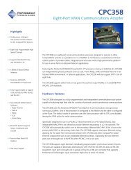
Datasheet<br />
Table 16: Ultra DMA Data Burst Timing Descriptions<br />
Name Comment Notes<br />
t 2CYCTYP Typical sustained average two cycle time<br />
t CYC Cycle time allowing for asymmetry and clock variations (from STROBE edge to STROBE edge)<br />
t 2CYC Two cycle time allowing for clock variations (from rising edge to next rising edge or from falling edge to<br />
next falling edge of STROBE)<br />
t DS Data setup time at recipient (from data valid until STROBE edge) 2, 5<br />
t DH Data hold time at recipient (from STROBE edge until data may become invalid) 2, 5<br />
t DVS Data valid setup time at sender (from data valid until STROBE edge) 3<br />
t DVH Data valid hold time at sender (from STROBE edge until data may become invalid) 3<br />
t CS CRC word setup time at device 2<br />
t CH CRC word hold time device 2<br />
t CVS CRC word valid setup time at host (from CRC valid until –DMACK negation) 3<br />
t CVH CRC word valid hold time at sender (from –DMACK negation until CRC may become invalid) 3<br />
t ZFS Time from STROBE output released-to-driving until the first transition of critical timing<br />
t DZFS Time from data output released-to driving until the first transition of critical timing<br />
t FS First STROBE time (for device to first negate DSTROBE from STOP during a data in burst)<br />
t LI Limited interlock time 1<br />
t MLI Interlock time with minimum 1<br />
t UI Unlimited interlock time 1<br />
t AZ Maximum time allowed for output drivers to release (from asserted or negated)<br />
t ZAG Minimum delay time required for output<br />
t ZAD Drives to assert or negate (from released)<br />
t ENV Envelope time(from –DMACK to STOP and –HDMARDY during data in burst initiation and from DMACK to<br />
STOP during data out burst initiation)<br />
t RFS Ready-to-final-STROBE time(no STROBE edges shall be sent this long after negation of –DMARDY)<br />
t RP Ready to pause time (that recipient shall wait to pause after negating –DMARDY)<br />
t IORDYZ Maximum time before releasing IORDY<br />
t ZIORDY Minimum time before driving IORDY 4<br />
t ACK Setup and hold times for –DMACK (before assertion or negation)<br />
Time from STROBE edge to negation of DMARQ or assertion of STOP (when sender terminates a burst)<br />
t SS<br />
Note:<br />
1) The parameters t UI , t MLI (in Figure 14: Ultra DMA Data-In Burst Device Termination Timing and Figure 15: Ultra DMA Data-in Burst Host<br />
Termination Timing), and t LI indicate sender-to-recipient or recipient-to-sender interlocks, i.e., one agent (either sender or recipient) is waiting for<br />
the other agent to respond with a signal before proceeding. t UI is an unlimited interlock that has no maximum time value. t MLI is a limited time-out<br />
that has a defined minimum. t LI is a limited time-out that has a defined maximum.<br />
2) 80-condutor cabling shall be required in order to meet setup (t DS , t CS ) and hold (t DH , tCH) times in modes greater than 3) Timing for t DVS , t DVH , t CVS and<br />
t CVH shall be met for lumped capacitive loads of 15 and 40 pF at the connector where the Data and STROBE signals have the same capacitive load<br />
value. Due to reflections on the cable, these timing measurements are not valid in a normally functioning system.<br />
4) For all modes the parameter t ZIORDY may be greater than t ENV due to the fact that the host has a pull-up on IORDY- giving it a known state when<br />
released.<br />
5) The parameters t DS and t DH for mode 5 are defined for a recipient at the end of the cable only in a configuration with a single device located at the<br />
end of the cable. This could result in the minimum values for t DS and t DH for mode 5 at the middle connector being 3.0 and 3.9 ns respectively.<br />
Rev. A.5 27/45 Mar. 2009