product guide cr-h, crn-h, cre-h, crne-h
product guide cr-h, crn-h, cre-h, crne-h
product guide cr-h, crn-h, cre-h, crne-h

Create successful ePaper yourself
Turn your PDF publications into a flip-book with our unique Google optimized e-Paper software.
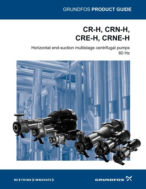
GRUNDFOS PRODUCT GUIDE<br />
CR-H, CRN-H,<br />
CRE-H, CRNE-H<br />
Horizontal end-suction multistage centrifugal pumps<br />
60 Hz
Contents<br />
Mission 3<br />
Product overview<br />
Introduction 4<br />
Performance range 5<br />
Applications 6<br />
Product range 7<br />
Pump 8<br />
Motor 8<br />
Electrical data and approvals 8<br />
Optional motors 8<br />
Motor protection 8<br />
Terminal box positions 9<br />
Ambient temperature 9<br />
Viscosity 9<br />
Product overview for E-pumps<br />
Examples of E-pump applications 10<br />
Control of E-pumps<br />
Control options of E-pumps 11<br />
Control modes for E-pumps 11<br />
Construction<br />
CR(E), CRN(E) 1s, 1, 3, 5, 10, 15 and 20 H 13<br />
CR(E), CRN(E) 32, 45, 64, and 90 H 14<br />
Type key and codes<br />
Type key 15<br />
Codes 15<br />
Operating and inlet pressure<br />
Maximum operating pressure and temperature range 16<br />
Operating range of the shaft seal 17<br />
Maximum inlet pressure 18<br />
Selection and sizing<br />
Selection of pumps 19<br />
Minimum inlet pressure - NPSHA 22<br />
How to read the curve charts<br />
Guidelines to the curve charts 23<br />
Curve charts/technical data<br />
CR, CRN 1s H GA 24<br />
CR, CRN, CRE, CRNE 1 H GA 26<br />
CR, CRN, CRE, CRNE 3 H GA 28<br />
CR, CRN, CRE, CRNE 5 H GA 30<br />
CR, CRN, CRE, CRNE 10 H G22 32<br />
CR, CRN, CRE, CRNE 10 H GA/G05 34<br />
CR, CRN, CRE, CRNE 15 H G22 37<br />
CR, CRN, CRE, CRNE 15 H GA/G05 39<br />
CR, CRN, CRE, CRNE 15 H GB 42<br />
CR, CRN, CRE, CRNE 20 H G22 44<br />
CR, CRN, CRE, CRNE 20 H GA/G05 46<br />
CR, CRN, CRE, CRNE 20 H GB 49<br />
CR, CRN, CRE, CRNE 32 H G22 51<br />
CR, CRN, CRE, CRNE 32 H GA/G05 53<br />
CR, CRN, CRE, CRNE 32 H GB/G50 56<br />
CR, CRN, CRE, CRNE 32 H GC/G10/G60 59<br />
CR, CRN, CRE, CRNE 45 H G33 63<br />
CR, CRN, CRE, CRNE 45 H GB/G20/G50 65<br />
CR, CRN, CRE, CRNE 45 H GC/G10/G30/G60 69<br />
CR, CRN, CRE, CRNE 64 H G44 74<br />
CR, CRN, CRE, CRNE 64 H GC/G10/G30/G60 76<br />
CR, CRN, CRE, CRNE 64 H G20/G50 81<br />
CR, CRN, CRE, CRNE 64 H G40/G70 84<br />
CR, CRN 90 H G44 87<br />
CR, CRN 90 H G20 89<br />
CR, CRN 90 H G30/G60 91<br />
CR, CRN 90 H G40/G70 94<br />
Motor data<br />
Motors for CR-H, CRN-H, CRE-H, CRNE-H pumps 97<br />
Pumped liquids<br />
Pumped liquids 100<br />
List of pumped liquids 100<br />
Accessories<br />
CR(E)-H, CRN(E) baseplate 103<br />
Baseplate selection 104<br />
Baseplate dimensions and weight 105<br />
Pipework connection 107<br />
Potentiometer for CRE-H, CRNE-H 108<br />
G10-LON interface for CRE-H, CRNE-H 108<br />
Remote control, R100 108<br />
EMC filter for CRE-H, CRNE-H 108<br />
Sensors for CRE-H, CRNE-H 108<br />
Gauges for CR(E)-H, CRN(E)-H 108<br />
MP 204 motor protector 109<br />
Variants 110<br />
Submittal data sheet<br />
Submittal data 111<br />
Quotation text<br />
CR-H, CRN-H, CRE-H, CRNE-H 113<br />
Further <strong>product</strong> documentation<br />
WebCAPS 115<br />
WinCAPS 116<br />
2
Mission<br />
CR-H, CRN-H, CRE-H, CRNE-H<br />
It is our mission — the basis of our existence — to successfully develop, produce and sell high-quality pumps and<br />
pumping systems world-wide, contributing to a better quality of life and a healthy environment<br />
Bjerringbro, Denmark<br />
Fresno, California<br />
Olathe, Kansas<br />
Monterrey, Mexico Allentown, Pennsylvania Oakville, Ontario<br />
• World's leading pump company<br />
• World's largest manufacturer of circulator pumps, covering more than 50% of the global market<br />
• World headquarters in Denmark<br />
• North American headquarters in Kansas City - Manufacturing in Fresno, California<br />
• 82 companies in 45 countries<br />
• More than 16 million motors and pumps produced annually worldwide<br />
• North American companies operating in USA, Canada and Mexico<br />
• Continuous reinvestment in growth and development enables the company to<br />
BE responsible, THINK ahead, and INNOVATE<br />
3
Product overview<br />
CR-H, CRN-H, CRE-H, CRNE-H<br />
Introduction<br />
This data booklet deals with CR-H and CRN-H<br />
horizontal end suction pumps as well as CRE-H and<br />
CRNE-H pumps.<br />
CR-H, CRN-H<br />
There is also a full range of CR-H, CRN-H pumps with<br />
standard Grundfos connection sizes that are optimized<br />
to give greater performance and efficiency.<br />
CRE-H, CRNE-H<br />
Fig. 1 CR-H pumps<br />
CR-H, CRN-H pumps are horizontal end suction pumps<br />
typically mounted on baseplates. The end suction<br />
design enables the pump to be installed horizontally in<br />
traditional, end suction design piping where the pump<br />
has an axial suction port and a radial center line<br />
discharge port. This design allows “back pull-out”<br />
capability so that most models can be serviced without<br />
removing the volute from the pipe system.<br />
Grundfos CR-H, CRN-H pump range includes various<br />
pump sizes and various numbers of stages to provide<br />
the flow and the pressure required.<br />
CR-H, CRN-H pumps are suitable for a variety of<br />
applications from pumping of potable water to pumping<br />
of chemicals. The pumps are therefore used in a wide<br />
variety of pumping systems where the performance and<br />
material of the pump meet specific demands.<br />
The CR-H, CRN-H pumps consist of three main<br />
components: the motor, the pump unit, and the<br />
baseplate.<br />
The pump unit consists of optimized hydraulics, various<br />
flange connections, a pump head, an end suction<br />
volute, and various other parts.<br />
CR-H, CRN-H pumps are available in various material<br />
versions according to the pumped liquid.<br />
CR-H, CRN-H pumps can be selected that meet ASME<br />
B73.1 dimensional standards for suction and discharge<br />
piping as well as many of the baseplate dimensional<br />
standards.CR-H, CRN-H pumps do not fully comply<br />
with the ASME B73.1 specification.<br />
TM04 3882<br />
Fig. 1 CRE-H pumps<br />
CRE-H, CRNE-H pumps are built on the basis of<br />
CR-H, CRN-H pumps. CRE-H, CRNE-H pumps belong<br />
to the so-called E-pump family and are referred to as<br />
E-pumps. The difference between the CR-H, CRN-H<br />
and the CRE-H, CRNE-H pump range is the motor.<br />
CRE-H, CRNE-H pumps are fitted with an E-motor with<br />
built-in frequency control. The CRE-H, CRNE-H pump<br />
has a Grundfos MLE motor.<br />
Frequency control enables continuously variable<br />
control of motor speed, which makes it possible to set<br />
the pump to operation at any duty point. The aim of<br />
continuously variable control of the motor speed is to<br />
adjust the performance to a given requirement.<br />
CRE-H, CRNE-H pumps are available with an attached<br />
pressure sensor connected to a frequency control.<br />
The pump materials are the same as those of the<br />
CR-H, CRN-H.<br />
Selecting a CRE-H, CRNE-H pump<br />
Select a CRE-H, CRNE-H pump if:<br />
• controlled operation is required, i.e. consumption<br />
fluctuates.<br />
• constant pressure is required.<br />
• communication with the pump is required.<br />
Adaptation of performance through frequencycontrolled<br />
speed control offers obvious advantages:<br />
• energy savings<br />
• in<strong>cr</strong>eased comfort<br />
• control and monitoring of the pump performance.<br />
See pages 10 - 12 for more information about E-pumps.<br />
TM04 4177 0909<br />
4
300<br />
[m]<br />
100<br />
80<br />
40<br />
50<br />
300<br />
[m]<br />
100<br />
80<br />
40<br />
50<br />
[ft]<br />
H<br />
800<br />
1000<br />
80<br />
100<br />
80<br />
[%]<br />
[ft]<br />
H<br />
800<br />
1000<br />
80<br />
100<br />
80<br />
[%]<br />
1<br />
s<br />
C<br />
R<br />
1<br />
H<br />
(<br />
E<br />
)<br />
C<br />
R<br />
3<br />
H<br />
(<br />
E<br />
)<br />
C<br />
R<br />
2 3 4 6 8 10 15 20 30 40 60 80 100 150 200 300 400 600 800<br />
1<br />
[US GPM]<br />
Q<br />
2 3 4 6 8 10 15 20 30 40 60 80 100 150 200 300 400 600 800<br />
1<br />
[US GPM]<br />
Q<br />
E<br />
1<br />
C<br />
R<br />
E<br />
3<br />
C<br />
R<br />
E<br />
5<br />
C<br />
R<br />
4 6 8 10 15 20 30 40 60 80 100 150 200 300 400 600<br />
3<br />
[US GPM]<br />
Q<br />
4 6 8 10 15 20 30 40 60 80 100 150 200 300 400 600<br />
3<br />
[US GPM]<br />
Q<br />
5<br />
H<br />
(<br />
E<br />
)<br />
C<br />
R<br />
0<br />
H<br />
E<br />
1<br />
C<br />
R<br />
1<br />
0<br />
(<br />
E<br />
)<br />
C<br />
R<br />
5<br />
H<br />
E<br />
1<br />
C<br />
R<br />
1<br />
5<br />
(<br />
E<br />
)<br />
C<br />
R<br />
2<br />
0<br />
0<br />
H<br />
E<br />
2<br />
C<br />
R<br />
(<br />
E<br />
)<br />
C<br />
R<br />
3<br />
2<br />
(<br />
E<br />
)<br />
C<br />
R<br />
2<br />
H<br />
E<br />
3<br />
C<br />
R<br />
4<br />
5<br />
(<br />
E<br />
)<br />
C<br />
R<br />
5<br />
H<br />
E<br />
4<br />
C<br />
R<br />
6<br />
4<br />
(<br />
E<br />
)<br />
C<br />
R<br />
4<br />
H<br />
E<br />
6<br />
C<br />
R<br />
9<br />
0<br />
C<br />
R<br />
Product overview<br />
CR-H, CRN-H, CRE-H, CRNE-H<br />
Performance range<br />
CR-H, CRN-H<br />
H<br />
60 Hz<br />
200<br />
600<br />
400<br />
300<br />
H<br />
H<br />
H<br />
H<br />
H<br />
H<br />
200<br />
H<br />
60<br />
H<br />
30<br />
20<br />
60<br />
40<br />
10<br />
30<br />
20<br />
2 3 4 5 6 8 10 20 30 40 50 60 80 Q [m³/h]<br />
1<br />
Eff<br />
60<br />
40<br />
20<br />
0<br />
TM04 4552<br />
CRE-H, CRNE-H<br />
H<br />
60 Hz<br />
200<br />
600<br />
400<br />
300<br />
200<br />
60<br />
30<br />
20<br />
60<br />
H<br />
H<br />
H<br />
40<br />
10<br />
30<br />
20<br />
2 3 4 5 6 7 8 9 10 20 30 40 50 60 70 80 Q [m³/h]<br />
1<br />
Eff<br />
60<br />
20<br />
0<br />
TM04 9018<br />
40<br />
5
Product overview<br />
CR-H, CRN-H, CRE-H, CRNE-H<br />
Applications<br />
Application CR-H CRN-H CRE-H, CRNE-H<br />
Water supply<br />
Filtration and transfer at waterworks • •<br />
Distribution from waterworks • •<br />
Pressure boosting in mains • •<br />
Pressure boosting in high-rise buildings, hotels, etc. • •<br />
Pressure boosting for industrial water supply • •<br />
Industry<br />
Pressure boosting...<br />
process water systems • • •<br />
washing and cleaning systems • • •<br />
vehicle washing tunnels • •<br />
fire fighting systems<br />
•<br />
Liquid transfer...<br />
cooling and air-conditioning systems (refrigerants) • •<br />
boiler feed and condensate systems • •<br />
machine tools (cooling lubricants) • • •<br />
aquafarming • <br />
Special transfer duties...<br />
oils and alcohols • • •<br />
acids and alkalis<br />
•<br />
glycol and coolants • • •<br />
Water treatment<br />
Ultrafiltration systems • •<br />
Reverse osmosis systems • •<br />
Softening, ionizing, demineralizing systems • •<br />
Distillation systems • •<br />
Separators • • •<br />
Swimming pools • •<br />
Irrigation<br />
Field irrigation (flooding) • <br />
Sprinkler irrigation • •<br />
Drip-feed irrigation • <br />
• Recommended version.<br />
Alternative version.<br />
6
Product overview<br />
CR-H, CRN-H, CRE-H, CRNE-H<br />
Product range<br />
Range<br />
CR, CRE<br />
1s H<br />
CR, CRE<br />
1 H<br />
CR, CRE<br />
3 H<br />
CR, CRE<br />
5 H<br />
CR, CRE<br />
10 H<br />
CR, CRE<br />
15 H<br />
CR, CRE<br />
20 H<br />
CR, CRE<br />
32 H<br />
CR, CRE<br />
45 H<br />
CR, CRE<br />
64 H<br />
Nominal flow rate [US GPM] 4.5 8 5 15 30 55 95 110 140 220 340 440<br />
Temperature range [°F] -4 to +250 -22 to +250<br />
Temperature range [°F]<br />
-40 to +356 -40 to +356<br />
— on request<br />
Max. working pressure [psi] 360 360 360 360 360 360 360 435 435 435 435<br />
Max. pump efficiency [%] 35 49 59 64 70 72 72 73 80 82 85<br />
CR-H pumps<br />
CR: Flow range [US GPM] 0.5 - 5.7 1 - 12 8 1 5 - 23 8 3 - 45 5.5 - 70 9.5 - 125 11 - 155 14 - 210 22 - 310 34 - 450 44 - 630<br />
CR: Max. pump pressure (H[ft]) 745 785 785 780 810 760 675 935 930 590 570<br />
CR: Motor power [Hp] 0 33 - 2 0 0.33 - 3.0 0 33 - 5 0 0.75 - 7.5 0.75 - 15 2.0 - 25 3 0 - 25 3.0 - 50 7 5 - 60 7.5 - 60 15 - 60<br />
CRE-H pumps<br />
CRE: Flow range [US GPM] 0 - 5.7 0 - 12 8 0 - 23.8 0 - 45 0 - 70 0 - 125 0 - 155 0 - 210 0 - 310 0 - 450 -<br />
CRE: Max. pump pressure (H[ft]) 745 785 785 780 670 385 270 225 120 100 -<br />
CRE: Motor power [Hp] 0 33 - 2 0 0.33 - 3.0 0 33 - 5 0 0.75 - 7.5 0.75 - 10 2.0 - 10 3 0 - 10 3.0 - 10 7 5 7.5 -<br />
Version<br />
CR-H, CRE-H versions:<br />
Cast iron and stainless steel AISI 304<br />
CRN-H, CRNE-H versions:<br />
Stainless steel AISI 316<br />
CR-H, CRE-H pipe connection<br />
• • • • • • • • • • •<br />
• • • • • • • • • • •<br />
ANSI connection type GA GA GA GA G22* G22* G22* G22* G33* G44* G44*<br />
ANSI flange class [lb] 125/ 250 125/ 250 125/ 250 125/ 250 125/ 250 125/ 250 125/ 250 125/ 250 125/ 250 125/ 250 125/ 250<br />
CRN-H, CRNE-H pipe connection<br />
ANSI connection type GA GA GA GA G22* G22* G22* G22* G33* G44* G44*<br />
ANSI flange class [lb] 150/ 300 150/ 300 150/ 300 150/ 300 150/ 300 150/ 300 150/ 300 150/ 300 150/ 300 150/ 300 150/ 300<br />
Pipe connection - inlet x discharge x impeller size reference<br />
GA ANSI 1.5" x 1" x 6", 1.5" x 1" x 8" • • • • • • • •<br />
G05 ANSI 2" x 1" x 10" • • • •<br />
GB ANSI 3" x 1.5" x 6", 3" x 1 5" x 8" • • • •<br />
GC ANSI 3" x 2" x 6" • • •<br />
G10 ANSI 3" x 2" x 6" • • •<br />
G50 ANSI 3" x 1.5" x 8", 3" x 1.5" x 10" • • •<br />
G60 ANSI 3" x 2" x 8", 3" x 2" x 10" • • • •<br />
G20 ANSI 3" x 1.5" x 13" • • •<br />
G30 ANSI 3" x 2" x 13" • • •<br />
G70 ANSI 4" x 3" x 8", 4" x 3" x 10" • •<br />
G40 ANSI 4" x 3" x 10", 4" x 3" x 13" • •<br />
G22 ANSI 2" x 2" • • • •<br />
G33 ANSI 3" x 3" • •<br />
G44 ANSI 4" x 4" • •<br />
• Available<br />
* There are a variety of flange size options available for this size CR-H (see list above). Selection should be based on replacement size or choose listed size for new<br />
installations.<br />
CR<br />
90 H<br />
7
Product overview<br />
CR-H, CRN-H, CRE-H, CRNE-H<br />
Pump<br />
The CR-H, CRN-H pump is a non-self-priming,<br />
horizontal, end suction, multistage centrifugal pump<br />
with enclosed impellers. The pumps are available with<br />
a Grundfos standard motor (CR-H, CRN-H pumps) or a<br />
frequency-controlled motor (CRE-H, CRNE-H pumps).<br />
The pump consists of a volute and a pump head. The<br />
chamber stack and the outer sleeve are secured<br />
between the pump head and the volute by means of<br />
staybolts. The volute has an end suction port and<br />
vertical centerline discharge port.<br />
All pumps are equipped with a maintenance-free<br />
mechanical shaft seal of the cartridge type.<br />
2<br />
3<br />
1<br />
Fig. 2 CR-H pump<br />
CR-H components<br />
Motor<br />
11<br />
10<br />
9<br />
5<br />
4<br />
Pos. Designation Pos. Designation<br />
1 Discharge 7 Coupling<br />
2 Suction 8 Motor<br />
3 Flange 9 Priming plug<br />
4 Staybolts 10 Shaft seal<br />
5 Outer sleeve 11 Impellers<br />
6 O-ring<br />
Grundfos standard motors - ML and Baldor® motors<br />
CR-H, CRN-H pumps are fitted with a Grundfos<br />
specified motor. The motors are all heavy-duty 2-pole,<br />
NEMA C-face motors. Three-phase motors greater<br />
than .75 hp are Premium efficient at minimum.<br />
Frequency-controlled motors - MLE motors<br />
CRE-H, CRNE-H pumps are fitted with a totally<br />
enclosed, fan-cooled, 2-pole frequency-controlled<br />
motor with integrated variable frequency drive.<br />
6<br />
7<br />
8<br />
TM04 4161 0510<br />
From 0.5 Hp to 1.5 Hp Grundfos offers pumps fitted with<br />
single-phase MLE motors (1 x 208-230 V). From 1.0 Hp<br />
to 10 Hp Grundfos offers pumps fitted with three-phase<br />
MLE motors (3 x 460-480 V). From 1.5 Hp to 7.5 Hp<br />
Grundfos offers pumps fitted with three-phase MLE<br />
motors (3 x 208-230 V).<br />
Electrical data and approvals<br />
Mounting<br />
designation NEMA<br />
Insulation<br />
F & B<br />
class<br />
Efficiency<br />
class<br />
Enclosure<br />
class<br />
60 Hz<br />
Standard<br />
voltages<br />
Approvals<br />
• Standard efficiency - single phase<br />
• Premium efficiency - three phase Grundfos ML and<br />
Baldor motors<br />
TEFC - Totally Enclosed Fan Cooled (Grundfos<br />
standard)<br />
ODP - Open Drip Proof - on request<br />
1 x 115/208-230 V<br />
3 x 208-230/460 V<br />
3 x 575 V<br />
Baldor<br />
Optional motors<br />
The Grundfos standard range of motors covers a wide<br />
variety of application demands. However, for special<br />
applications or operating conditions, custom-built motor<br />
solutions can be provided.<br />
For special applications or operating conditions,<br />
Grundfos offers custom-built motors such as:<br />
• explosion proof motors<br />
• motors with anti-condensation heating unit<br />
• low-noise motors<br />
• energy efficient and premium efficiency motors<br />
• motors with thermal protection.<br />
Motor protection<br />
ML/MLE<br />
Single-phase Grundfos specified motors up to 7.5 hp<br />
have a built-in thermal overload switch.<br />
Three-phase motors must be connected to a motor<br />
starter in accordance with local regulations.<br />
MLE motors<br />
CRE-H, CRNE-H pumps require no external motor<br />
protection. The MLE motor incorporates thermal<br />
protection against slow overloading and blocking.<br />
8
Product overview<br />
CR-H, CRN-H, CRE-H, CRNE-H<br />
Terminal box positions<br />
As standard the terminal box is mounted as shown in<br />
fig. 3.<br />
Example: From fig. 4 it appears that P 2 must be<br />
reduced to 88 % when a pump with a NEMA Premium<br />
efficiency, ML motor is installed 15,584 feet above sea<br />
level. At an ambient temperature of 167 °F, P 2 of an<br />
energy efficient motor must be reduced to 74 % of rated<br />
output.<br />
Position 12 Position 3<br />
Standard<br />
Standard<br />
ML, MLE<br />
Baldor<br />
Fig. 3 Terminal box positions<br />
TM02 18 05 2001<br />
Viscosity<br />
The pumping of liquids with densities or kinematic<br />
viscosities higher than those of water will cause a<br />
considerable pressure drop, a drop in the hydraulic<br />
performance and a rise in the power consumption.<br />
In such situations the pump should be equipped with a<br />
larger motor. For selection you may utilize Grundfos<br />
WinCAPS/WebCAPS. If in doubt, contact Grundfos.<br />
Ambient temperature<br />
If the ambient temperature exceeds the maximum<br />
temperature limits of the motor or the pump is installed<br />
at an altitude exceeding the altitude values in the chart<br />
below, the motor must not be fully loaded due to the risk<br />
of overheating.<br />
Overheating may result from excessive ambient<br />
temperatures or the low density and consequently low<br />
cooling effect of the air at high altitudes. In such cases,<br />
it may be necessary to use a motor with a higher rated<br />
output (P 2 ).<br />
P2<br />
[%]<br />
100<br />
2<br />
90<br />
80<br />
1<br />
70<br />
60<br />
50<br />
60 80 100 120 140 160 180<br />
T [°F]<br />
3280 7382 11483 15584 ft<br />
Legend<br />
Fig. 4 Relationship between motor output (P 2 ) and<br />
ambient temperature/altitude<br />
Pos. Des<strong>cr</strong>iption<br />
1 NEMA energy efficient motors (EPAct)<br />
2 NEMA Premium efficiency motors<br />
TM03 4272 2006<br />
9
Product overview for E-pumps<br />
CR-H, CRN-H, CRE-H, CRNE-H<br />
Examples of E-pump applications<br />
CRE-H, CRNE-H pumps are the ideal solution in a<br />
number of applications characterized by a need for<br />
variable flow at constant pressure. The pumps are<br />
suited for water supply systems and pressure boosting,<br />
but also industrial applications.<br />
Depending on the nature of the application, the pumps<br />
offer energy-savings, in<strong>cr</strong>eased comfort or improved<br />
processing.<br />
E-pumps in the service of industry<br />
Industry uses a large number of pumps in many<br />
different applications. Demands on pumps in terms of<br />
pump performance and mode of operation make speed<br />
control a must in many applications.<br />
Below are mentioned some of the applications in which<br />
E-pumps are often used.<br />
Constant pressure<br />
• Water supply<br />
• washing and cleaning systems<br />
• distribution from waterworks<br />
• humidifying systems<br />
• water treatment systems<br />
• process boosting systems, etc.<br />
Example: Within industrial water supply, E-pumps with<br />
integrated pressure sensors are used to ensure a<br />
constant pressure in the piping network. From the<br />
sensor, the E-pump receives inputs about changes of<br />
pressure as a result of changes in the consumption.<br />
The E-pump responds to the input by adjusting the flow<br />
until the pressure is equalized. As a result, the constant<br />
pressure is stabilized once more on the basis of a<br />
preset setpoint.<br />
Constant temperature<br />
• Air-conditioning systems at industrial plants<br />
• industrial cooling systems<br />
• industrial freezing systems<br />
• casting and molding tools, etc.<br />
Example: In industrial freezing systems, E-pumps with<br />
temperature sensors in<strong>cr</strong>ease comfort and lower<br />
operating costs compared with pumps without<br />
temperature sensors.<br />
An E-pump continuously adapts its performance to the<br />
changing demands reflected in the differences in<br />
temperature of the liquid circulating in the freezing<br />
system. Thus, the lower the demand for cooling, the<br />
smaller the quantity of liquid circulated in the system<br />
and vice versa.<br />
Constant flow or level<br />
• Steam boiler systems<br />
• condensate systems<br />
• sprinkler irrigation systems<br />
• chemical industry, etc.<br />
Example: In a steam boiler, it is important to be able to<br />
monitor and control pump operation to maintain a<br />
constant level of water in the boiler.<br />
By using an E-pump with level sensor mounted in the<br />
boiler, it is possible to maintain a constant water level.<br />
A constant water level ensures optimum and costefficient<br />
operation as a result of a stable steam<br />
<strong>product</strong>ion.<br />
Dosing<br />
• Chemical industry (i.e. control of pH-values)<br />
• petrochemical industry<br />
• degreasing systems<br />
• bleaching systems, etc.<br />
Example: In the petrochemical industry, E-pumps with<br />
pressure sensors are used as dosing pumps. The<br />
E-pumps help to ensure that the correct mixture ratio is<br />
achieved when more liquids are combined.<br />
E-pumps functioning as dosing pumps improve<br />
processing and offer energy-savings.<br />
E-pumps in commercial building services<br />
Commercial building services use E-pumps to maintain<br />
a constant pressure or a constant temperature based<br />
on a variable flow.<br />
E-pumps are used in applications such as:<br />
Constant pressure<br />
• Water supply in high-rise buildings i.e. office<br />
buildings, hotels, etc.<br />
Example: E-pumps with pressure sensors are used for<br />
water supply in high-rise buildings to ensure a constant<br />
pressure even at the highest draw-off point. As the<br />
consumption pattern and thus the pressure changes<br />
during the day, the E-pump continuously adapts its<br />
performance until the pressure is equalized.<br />
Constant temperature<br />
• Air-conditioning systems in hotels, schools, etc.<br />
• building cooling systems, etc.<br />
Example: E-pumps are an excellent solution in<br />
buildings where constant temperature is essential.<br />
E-pumps keep the temperature constant in<br />
air-conditioned, high-rise glass buildings, irrespective<br />
of the seasonal fluctuations of the out-door temperature<br />
and various heat impacts inside the building.<br />
10
Control of E-pumps<br />
CR-H, CRN-H, CRE-H, CRNE-H<br />
Control options of E-pumps<br />
Communication with CRE-H, CRNE-H pumps is<br />
possible by means of the following interfaces:<br />
• a central management system<br />
• remote control (Grundfos R100) or<br />
• a control panel.<br />
The purpose of controlling an E-pump is to monitor and<br />
control the pressure, temperature, flow and liquid level<br />
of the system.<br />
Central management system<br />
Communication with the E-pump is possible even<br />
though the operator is not present near the E-pump.<br />
Communication is enabled by having the E-pump<br />
connected to a central management system allowing<br />
the operator to monitor and change control modes and<br />
setpoint settings of the E-pump.<br />
Remote control<br />
The R100 remote control produced by Grundfos is<br />
available as an accessory.<br />
The operator communicates with the E-pump by<br />
pointing the IR-signal transmitter at the control panel of<br />
the E-pump terminal box.<br />
Fig. 6 R100 remote control<br />
The R100 enables monitoring and changing of control<br />
modes and settings of the E-pump.<br />
TM00 4498 2802<br />
Control panel<br />
The control panel of the E-pump terminal box makes it<br />
possible to change the setpoint settings manually.<br />
Light fields<br />
LON-bus connection<br />
G10-LON<br />
Interface<br />
Indicator lights<br />
Buttons<br />
TM00 7600 1196<br />
Fig. 7 Control panel on CRE-H pump<br />
GENIbus connection<br />
E-pump<br />
Fig. 5 Structure of a central management system<br />
TM02 6592 1103<br />
Control modes for E-pumps<br />
Grundfos offers CRE-H, CRNE-H pumps in two<br />
different variants:<br />
• CRE-H, CRNE-H with integrated pressure sensor<br />
• CRE-H, CRNE-H without sensor.<br />
CRE-H, CRNE-H with integrated pressure sensor<br />
CRE-H, CRNE-H pumps with integrated pressure<br />
sensor are suitable for applications where you want to<br />
control the pressure after the pump, irrespective of the<br />
flow. See the section Examples of E-pump applications<br />
on page 10 for further information.<br />
Signals of pressure changes in the piping system are<br />
transmitted continuously from the sensor to the pump.<br />
11
Control of E-pumps<br />
CR-H, CRN-H, CRE-H, CRNE-H<br />
The pump responds to the signals by adjusting its<br />
performance up or down to compensate for the<br />
pressure difference between the actual and the desired<br />
pressure. As this adjustment is a continuous process, a<br />
constant pressure is maintained in the piping system.<br />
Min.<br />
H<br />
Q<br />
Max.<br />
TM00 9323 4796<br />
Fig. 10 Constant curve mode<br />
Fig. 8 CRE-H, CRNE-H pump<br />
A CRE-H, CRNE-H pump with integrated pressure<br />
sensor facilitates installation and commissioning.<br />
CRE-H, CRNE-H pumps with integrated pressure<br />
sensor can be set to:<br />
• constant-pressure mode (factory setting) or<br />
• constant-curve mode.<br />
In constant-pressure mode, the pump maintains a<br />
preset pressure after the pump, irrespective of the flow.<br />
See fig. 9.<br />
TM04 4177 0909<br />
CRE-H, CRNE-H without sensor<br />
CRE-H, CRNE-H pumps without sensors are suitable<br />
for applications where:<br />
• uncontrolled operation is required<br />
• you want to fit another sensor later in order to<br />
control the flow, temperature, differential<br />
temperature, liquid level, pH value, etc at some<br />
arbitrary point in the system.<br />
CRE-H, CRNE-H pumps without sensor can be set to:<br />
• controlled-operation mode or<br />
• uncontrolled-operation mode (factory-setting).<br />
In controlled-operation mode, the pump adjusts its<br />
performance to the desired setpoint. See fig. 11.<br />
H<br />
H<br />
Hset<br />
Qset<br />
Q<br />
TM02 7264 2803<br />
Q<br />
TM00 9322 4796<br />
Fig. 11 Constant flow mode<br />
In uncontrolled-operation mode, the pump operates<br />
according to the constant curve set. See fig. 12.<br />
Fig. 9 Constant pressure mode<br />
H<br />
In constant-curve mode, the pump is not controlled. It<br />
can be set to pump according to a preset pump<br />
characteristic within the range from min. curve to max.<br />
curve. See fig. 10.<br />
Min.<br />
Max.<br />
Q<br />
Fig. 12 Constant curve mode<br />
CRE-H, CRNE-H pumps can be fitted with sensor types<br />
listed on page 108.<br />
TM00 9323 4796<br />
12
Construction<br />
CR-H, CRN-H, CRE-H, CRNE-H<br />
CR(E) 1s, 1, 3, 5, 10, 15 and 20 H<br />
CRN(E) 1s, 1, 3, 5, 10, 15 and 20 H<br />
TM04 4524 1509<br />
Fig. 13 Product photo<br />
Fig. 15 Product photo<br />
TM04 4269 4910<br />
TM04 9676 4910<br />
TM04 9547 4510<br />
2<br />
Fig. 14 Sectional drawing<br />
Materials: CR(E)-H<br />
Pos. Designation Materials AISI/ASTM<br />
1 Pump head Cast iron A 48-30 B<br />
3 Shaft Stainless steel<br />
AISI 316 1)<br />
AISI 431 2)<br />
4 Impeller Stainless steel AISI 304<br />
5 Chamber Stainless steel AISI 304<br />
6 Outer sleeve Stainless steel AISI 304<br />
7 O-ring for outer sleeve EPDM or FKM<br />
8<br />
Suction-discharge<br />
housing<br />
Ductile iron A 80-55-06<br />
9 Neck ring PTFE<br />
10 Shaft seal Cartridge type<br />
Bearing rings Silicon carbide<br />
Rubber parts<br />
EPDM or FKM<br />
11 Foot Ductile iron A 80-55-06<br />
12 Flange ring Ductile iron A 80-55-06<br />
13 Support bracket Stainless steel AISI 304<br />
14 Sleeve flange 5) Stainless steel CF 8M 4)<br />
15 Discharge port Ductile iron A 80-55-06<br />
1) CR-H, CRE-H 1s, 1, 3, 5<br />
2) CR-H, CRE-H 10, 15, 20<br />
3) Stainless steel available on request<br />
4) CF 8M is cast equivalent of AISI 316 stainless steel<br />
5) CR-H, CRE-H 10, 15, 20 only; CR-H, CRE-H 1s, 1, 3, 5 do not have a<br />
sleeve flange.<br />
6) CRN-H, CRNE-H 1s, 1, 3, 5<br />
7) CRN-H, CRNE-H 10, 15, 20<br />
Fig. 16 Sectional drawing<br />
Materials: CRN(E)-H<br />
Pos. Designation Materials AISI/ASTM<br />
1 Pump head Cast iron 3) A 48-30 B<br />
2 Pump head cover Stainless steel CF 8M 4)<br />
3 Shaft Stainless steel<br />
AISI 316 6)<br />
AISI 329 7)<br />
4 Impeller Stainless steel AISI 316<br />
5 Chamber Stainless steel AISI 316<br />
6 Outer sleeve Stainless steel AISI 316<br />
7 O-ring for outer sleeve EPDM or FKM<br />
8<br />
Suction-discharge<br />
housing<br />
Stainless steel CF 8M 4)<br />
9 Neck ring PTFE<br />
10 Shaft seal Cartridge type<br />
Bearing rings<br />
Silicon carbide<br />
Rubber parts<br />
EPDM or FKM<br />
11 Foot Cast iron 3) A 48-30 B<br />
12 Flange ring Ductile iron 3) A 65-45-12<br />
13 Support bracket Stainless steel AISI 304<br />
14 Sleeve flange Stainless steel CF 8M 4)<br />
15 Discharge port Stainless steel CF 8M 4)<br />
13
Construction<br />
CR-H, CRN-H, CRE-H, CRNE-H<br />
CR(E) 32, 45, 64, and 90 H<br />
CRN(E) 32, 45, 64, and 90 H<br />
TM04 4525 1509<br />
Fig. 17 Product photo<br />
Fig. 19 Product photo<br />
TM04 4270 1009<br />
TM04 4270 1009<br />
TM04 9548 4510<br />
Fig. 18 Sectional drawing<br />
Materials: CR(E)-H<br />
Pos. Designation Materials AISI/ASTM<br />
1 Pump head Ductile iron A 80-55-06<br />
2 Motor stool Cast iron A 48-30 B<br />
3 Shaft Stainless steel AISI 431<br />
4 Impeller Stainless steel AISI 304<br />
5 Chamber Stainless steel AISI 304<br />
6 Outer sleeve Stainless steel AISI 304<br />
7<br />
O-ring for outer<br />
sleeve<br />
EPDM or FKM<br />
8<br />
Suction-discharge<br />
housing<br />
Ductile iron A 80-55-06<br />
9 Neck ring Acoflon 215<br />
10 Shaft seal Cartridge type<br />
Bearing ring Bronze<br />
Rubber parts EPDM or FKM<br />
11 Foot Ductile iron A 80-55-06<br />
12 Flange ring Ductile iron A 80-55-06<br />
13 Support bracket Stainless steel AISI 304<br />
14 Sleeve flange Stainless steel CF 8M 2)<br />
15 Discharge port Ductile iron A 80-55-06<br />
16<br />
Bottom bearing<br />
ring<br />
Tungsten carbide/<br />
Tungsten carbide<br />
1) Stainless steel available on request<br />
2) CF 8M is cast equivalent of AISI 316 stainless steel<br />
Fig. 20 Sectional drawing<br />
Materials: CRN(E)-H<br />
Pos. Designation Materials AISI/ASTM<br />
1 Pump head Stainless steel CF 8M 2)<br />
2 Motor stool Cast iron A 48-30 B<br />
3 Shaft Stainless steel SAF 2205<br />
4 Impeller Stainless steel AISI 316<br />
5 Chamber Stainless steel AISI 316<br />
6 Outer sleeve Stainless steel AISI 316<br />
7<br />
O-ring for outer<br />
sleeve<br />
EPDM or FKM<br />
8<br />
Suction-discharge<br />
housing<br />
Stainless steel CF 8M 2)<br />
9 Neck ring Acoflon 215<br />
10 Shaft seal Cartridge type<br />
Bearing ring<br />
Carbon-graphite<br />
filled PTFE<br />
Rubber parts EPDM or FKM<br />
11 Foot Ductile iron 1) A 80-55-06<br />
12 Flange ring Ductile iron 1) A 65-45-12<br />
13 Support bracket Stainless steel AISI 304<br />
14 Sleeve flange Stainless steel CF 8M 2)<br />
15 Discharge port Stainless steel CF 8M 2)<br />
16<br />
Bottom bearing<br />
ring<br />
Tungsten carbide/<br />
Tungsten carbide<br />
14
Type key and codes<br />
CR-H, CRN-H, CRE-H, CRNE-H<br />
Type key<br />
Example H-GA-A-E-HQQE<br />
Pipe connection<br />
CR-H, CRE-H<br />
(inlet x discharge x impeller size reference) 2<br />
Example<br />
CR E 5 s -4 -2 H -GA -G -E -HQQE GA ANSI 1.5" x 1" x 6", 1.5" x 1" x 8"<br />
Type range<br />
G05 ANSI 2" x 1" x 10"<br />
GB ANSI 3" x 1.5" x 6", 3" x 1.5" x 8"<br />
Pump with integrated<br />
frequency control<br />
GC ANSI 3" x 2" x 6"<br />
Rated flow rate [m 3 /h]<br />
G10 ANSI 3" x 2" x 6"<br />
All impellers with reduced diameter<br />
G50 ANSI 3" x 1.5" x 8", 3" x 1.5" x 10"<br />
(applies only to CR, CRN 1s H)<br />
G60 ANSI 3" x 2" x 8", 3" x 2" x 10"<br />
Number of impellers<br />
G20 ANSI 3" x 1.5" x 13"<br />
Number of reduced diameter impellers<br />
G30 ANSI 3" x 2" x 13"<br />
(applies only to<br />
G70 ANSI 4" x 3" x 8" , 4" x 3" x 10"<br />
CR(E), CRN(E) 32, 45, 64, 90 H)<br />
G40 ANSI 4" x 3" x 10", 4" x 3" x 13"<br />
Code for pump version<br />
G22 ANSI 2" x 2"<br />
Code for pipe connection<br />
G33 ANSI 3" x 3"<br />
Code for materials<br />
G44 ANSI 4" x 4"<br />
Code for rubber parts<br />
Materials<br />
Code for shaft seal<br />
A Basic version<br />
D Carbon-graphite filled PTFE (bearings)<br />
G Wetted parts AISI 316<br />
Codes<br />
All parts stainless steel,<br />
GI<br />
wetted parts AISI 316<br />
Example<br />
H -GA -A -E -H QQ E<br />
K Bronze (bearings)<br />
Pump version<br />
S SiC bearings + PTFE neck rings<br />
HB Oversize motor<br />
X Special version<br />
HE Certificate/approval<br />
Code for rubber parts<br />
HF CR pump for high temperatures<br />
E EPDM<br />
(air cooled top assembly)<br />
F FXM<br />
H Basic horizontal version<br />
K FFKM<br />
HI Different pressure rating<br />
V FKM<br />
HJ Pump with different max speed<br />
Shaft seal<br />
HK Pump with low NPSH<br />
H Balanced cartridge seal with O-ring<br />
HN Fitted with sensor<br />
K Metal bellows cartridge seal<br />
HP Undersize motor<br />
O Double seal, back-to-back<br />
HT Over size motor (two flange sizes bigger)<br />
P Double seal, tandem<br />
X Special version 1) X Special version<br />
B Carbon, synthetic resin-impregnated<br />
H Cemented tungsten carbide, embedded (hybrid)<br />
Q Silicon carbide<br />
U Cemented tungsten carbide<br />
X Other ceramics<br />
E EPDM<br />
F FXM<br />
K FFKM<br />
V FKM<br />
1) If a pump incorporates more than two pump versions, the code for the<br />
pump version is X. X also indicates special pump versions not listed<br />
above.<br />
2) The pipe connection code designates the pump as a CR horizontal<br />
end-suction pump.<br />
15
Operating and inlet pressure<br />
CR-H, CRN-H, CRE-H, CRNE-H<br />
Maximum operating pressure and temperature range<br />
ANSI flanged<br />
TM04 4039 0609<br />
Pump type<br />
Operating<br />
pressure<br />
CR(E), CRN(E) 1s-2 H 1s-17 H 232 psi (16 bar)*<br />
CR(E), CRN(E) 1s-19 H 1s-27 H 362 psi (25 bar)<br />
CR(E), CRN(E) 1-2 H 1-17 H 232 psi (16 bar)*<br />
CR(E), CRN(E) 1-19 H 1-27 H 362 psi (25 bar)<br />
CR(E), CRN(E) 3-2 H 3-15 H 232 psi (16 bar)*<br />
CR(E), CRN(E) 3-17 H 3-25 H 362 psi (25 bar)<br />
CR(E), CRN(E) 5-2 H 5-15 H 232 psi (16 bar)*<br />
CR(E), CRN(E)5-16 H 5-24 H 362 psi (25 bar)<br />
CR(E), CRN(E) 10-1 H 10-10 H 232 psi (16 bar)*<br />
CR(E), CRN(E) 10-12 H 10-17 H 362 psi (25 bar)<br />
CR(E), CRN(E) 15-1 H 15-8 H 232 psi (16 bar)*<br />
CR, CRN 15-9 H 15-12 H 362 psi (25 bar)<br />
CR(E), CRN(E) 20-1 H 20-7 H 232 psi (16 bar)*<br />
CR, CRN 20-8 H 20-10 H 362 psi (25 bar)<br />
CR(E), CRN(E) 32-1-1 H 32-5 H 232 psi (16 bar)*<br />
CR, CRN 32-6-2 H 32-11-2 H 435 psi (30 bar)<br />
CR(E), CRN(E) 45-1-1 H 45-4 H 232 psi (16 bar)*<br />
CR, CRN 45-5-2 H 45-8-1 H 435 psi (30 bar)<br />
CR(E), CRN(E) 64-1-1 H 64-3 H 232 psi (16 bar)*<br />
CR, CRN 64-4-2 H 64-5-2 H 435 psi (30 bar)<br />
CR, CRN 90-1-1 H 90-3 H 232 psi (16 bar)*<br />
CR, CRN 90-4-2 H 90-4-1 H 435 psi (30 bar)<br />
Liquid<br />
temperature<br />
range<br />
(-4°F to +248°F)<br />
(-20°C to +120°C)<br />
(-4°F to +248°F)<br />
(-20°C to +120°C)<br />
(-22°F to +248°F)<br />
(-30°C to +120°C)<br />
* These pumps come standard with 125/150 lb. ANSI flanges.<br />
High pressure versions are available which will raise the operating pressure to the next rating.<br />
16
Operating and inlet pressure<br />
CR-H, CRN-H, CRE-H, CRNE-H<br />
Operating range of the shaft seal<br />
The operating range of the shaft seal depends on operating<br />
pressure, pump type, type of shaft seal and liquid<br />
temperature. The following curves apply to clean water<br />
and water with anti-freeze liquids. For selecting the<br />
right shaft seal, see List of pumped liquids on page 100.<br />
CR(E), CRN(E) 1s H through CR 20 H<br />
p<br />
[bar]<br />
25<br />
20<br />
15<br />
10<br />
5<br />
0<br />
p<br />
[psi]<br />
400<br />
300<br />
200<br />
100<br />
HQQE<br />
HQQE<br />
HQQV<br />
0<br />
-40 0 40 80 120 160 200 240 t [°F]<br />
-40 -20 0 20 40 60 80 100 t [°C]<br />
Fig. 21 Operating range of standard shaft seals for<br />
CR(E), CRN(E) 1s H to CR 20 H<br />
CR(E), CRN(E) 32 H through CR 90 H<br />
p<br />
[bar]<br />
30<br />
25<br />
20<br />
15<br />
10<br />
5<br />
0<br />
HQQE<br />
p<br />
[psi]<br />
500<br />
HQQE / HQQV HQQE<br />
400<br />
300<br />
KUHE / KUHV<br />
200<br />
KUBE / KUBV KUBE<br />
KUUE / KUUV<br />
100<br />
0<br />
-40 0 40 80 120 160 200 240 t [°F]<br />
KUUE<br />
KUUE<br />
KUUV<br />
-40 -20 0 20 40 60 80 100 t [°C]<br />
TM02 7537 1409<br />
TM04 4473 1409<br />
Shaft<br />
seal<br />
HQQE<br />
HQQV<br />
HUBE<br />
HUBV<br />
KUBE<br />
KUBV<br />
KUHE<br />
KUHV<br />
KUUE<br />
KUUV<br />
Des<strong>cr</strong>iption<br />
O-ring (balanced cartridge seal),<br />
SiC/SiC, EPDM<br />
O-ring (balanced cartridge seal),<br />
SiC/SiC, FKM<br />
O-ring (balanced cartridge seal),<br />
TC/carbon, EPDM<br />
O-ring (balanced cartridge seal),<br />
TC/carbon, FKM<br />
Metal bellows (balanced cartridge<br />
seal), TC/carbon, EPDM<br />
Metal bellows (balanced cartridge<br />
seal), TC/carbon, FKM<br />
Metal bellows (balanced cartridge<br />
seal), TC/carbon with embedded<br />
TC, EPDM<br />
Metal bellows (balanced cartridge<br />
seal), TC/carbon with embedded<br />
TC, FKM<br />
Metal bellows (balanced cartridge<br />
seal), TC/TC, EPDM<br />
Metal bellows (balanced cartridge<br />
seal), TC/TC, FKM<br />
TC = tungsten carbide.<br />
Max.<br />
temperature range<br />
[°F (C°)]<br />
– 22 °F to + 248 °F<br />
(– 30 °C to + 120 °C)<br />
– 4 °F to + 194 °F<br />
(– 30 °C to + 90 °C)<br />
+ 32 °F to + 248 °F<br />
(0 °C to + 120 °C)<br />
+ 32 °F to + 194 °F<br />
(0 °C to + 90 °C)<br />
+ 32 °F to + 248 °F<br />
(0 °C to + 120 °C)<br />
+ 32 °F to + 194 °F<br />
(0 °C to + 90 °C)<br />
+ 32 °F to + 194 °F<br />
(0 °C to + 90 °C)<br />
+ 32 °F to + 194 °F<br />
(0 °C to + 90 °C)<br />
– 22 °F to + 194 °F<br />
(–30 °C to + 90 °C)<br />
– 4 °F to + 194 °F<br />
(– 30 °C to + 90 °C)<br />
The pumping of liquids above 248 °F (120 °C) may<br />
result in periodical noise and reduced pump life.<br />
Standard CR-H, CRN-H pumps are not suitable for the<br />
pumping of liquids above 248 °F (120 °C) for long<br />
periods.<br />
See the Grundfos "Custom-built Pumps" Product Guide<br />
for information about pumps for extreme temperatures<br />
and special conditions.<br />
Fig. 22 Operating range of standard shaft seals for<br />
CR(E), CRN(E) 32 H to CR 90 H<br />
17
Operating and inlet pressure<br />
CR-H, CRN-H, CRE-H, CRNE-H<br />
Maximum inlet pressure<br />
The following table shows the maximum permissible<br />
inlet pressure. However, the current inlet pressure + the<br />
pressure against closed valve must always be lower<br />
than the maximum permissible operating pressure.<br />
If the maximum permissible operating pressure is<br />
exceeded, the bearing in the motor may be damaged<br />
and the life of the shaft seal reduced.<br />
Max. inlet pressure CR(E)-H, CRN(E)-H<br />
CR(E), CRN(E) 1s H<br />
CR 1s-2 H CR 1s-27 H<br />
CR(E), CRN(E) 1 H<br />
CR 1-2 H CR 1-25 H<br />
CR 1-27 H<br />
CR(E), CRN(E) 3 H<br />
CR 3-2 H CR 3-15 H<br />
CR 3-17 H CR 3-25 H<br />
CR(E), CRN(E) 5 H<br />
CR 5-2 H CR 5-9 H<br />
CR 5-10 H CR 5-24 H<br />
CR(E), CRN(E) 10 H<br />
CR 10-1 H CR 10-5 H<br />
CR 10-6 H CR 10-17 H<br />
CR(E), CRN(E) 15 H<br />
CR 15-1 H CR 15-2 H<br />
CR 15-3 H CR 15-12 H<br />
CR(E), CRN(E) 20 H<br />
CR 20-1 H<br />
CR 20-2 H CR 20-10 H<br />
145 psi (10 bar)<br />
145 psi (10 bar)<br />
217 psi (15 bar)<br />
145 psi (10 bar)<br />
217 psi (15 bar)<br />
145 psi (10 bar)<br />
217 psi (15 bar)<br />
116 psi (8 bar)<br />
145 psi (10 bar)<br />
116 psi (8 bar)<br />
145 psi (10 bar)<br />
116 psi (8 bar)<br />
145 psi (10 bar)<br />
Example of operating and inlet pressures<br />
The values for operating and inlet pressures shown in<br />
the tables must not be considered individually but must<br />
always be compared; see the following examples:<br />
Example 1:<br />
The following pump type has been selected:<br />
CR 5-20 H-GA-A-E<br />
Max. operating pressure:<br />
Max. inlet pressure:<br />
362 psi (25 bar)<br />
217 psi (15 bar)<br />
Discharge pressure against closed valve:<br />
282 psi (652 ft). See page 30.<br />
This pump is not allowed to start at an inlet pressure of<br />
217 psi, but at an inlet pressure of:<br />
362 – 282 = 80 psi (5.5 bar).<br />
Example 2:<br />
The following pump has been selected:<br />
CR 10-2 H-G05-A-E<br />
Max. operating pressure: 232 psi (16 bar)<br />
Max. inlet pressure: 116 psi (8 bar)<br />
Discharge pressure against closed valve:<br />
42 psi (97 ft). See page 32.<br />
This pump is allowed to start at an inlet pressure of<br />
116 psi (8 bar), as the discharge pressure is only 42 psi<br />
(2.9 bar), which results in an operating pressure of 116<br />
+ 42 = 158 psi (11 bar). On the contrary, the max.<br />
operating pressure of this pump is limited to 158 psi<br />
(11 bar), as a higher operating pressure will require an<br />
inlet pressure of more than 116 psi (8 bar).<br />
CR(E), CRN(E) 32 H<br />
CR 32-1-1 H CR 32-2 H<br />
CR 32-3-2 H CR 32-6 H<br />
CR 32-7-2 H CR 32-11-2 H<br />
CR(E), CRN(E) 45 H<br />
CR 45-1-1 H CR 45-1 H<br />
CR 45-2-2 H CR 45-3 H<br />
CR 45-4-2 H CR 45-8-1 H<br />
CR(E), CRN(E) 64 H<br />
CR 64-1-1 H<br />
CR 64-1 H CR 64-2-1 H<br />
CR 64-2 H CR 64-5-2 H<br />
CR, CRN 90 H<br />
CR 90-1-1 H CR 90-2-2 H<br />
CR 90-2-1 H CR 90-4-1 H<br />
58 psi (4 bar)<br />
145 psi (10 bar)<br />
217 psi (15 bar)<br />
58 psi (4 bar)<br />
145 psi (10 bar)<br />
217 psi (15 bar)<br />
58 psi (4 bar)<br />
145 psi (10 bar)<br />
217 psi (15 bar)<br />
145 psi (10 bar)<br />
217 psi (15 bar)<br />
18
Selection and sizing<br />
CR-H, CRN-H, CRE-H, CRNE-H<br />
Selection of pumps<br />
Selection of pumps should be based on:<br />
• duty point of the pump<br />
• sizing data such as pressure loss as a result of<br />
height differences, friction loss in the pipework,<br />
pump efficiency etc.<br />
• pump materials<br />
• piping dimensions<br />
• shaft seal<br />
• inlet pressure and operating pressure.<br />
Duty point of the pump<br />
From a duty point it is possible to select a pump on the<br />
basis of the curve charts in the section Curve charts/<br />
technical data starting on page 24.<br />
H<br />
[m]<br />
280<br />
260<br />
2 0<br />
220<br />
200<br />
180<br />
160<br />
1 0<br />
120<br />
100<br />
80<br />
60<br />
0<br />
20<br />
0<br />
H<br />
[ft]<br />
950<br />
900<br />
850<br />
800<br />
750<br />
700<br />
650<br />
600<br />
550<br />
500<br />
50<br />
00<br />
350<br />
300<br />
250<br />
200<br />
150<br />
100<br />
50<br />
-10<br />
-9<br />
-8<br />
-7<br />
-6<br />
-5<br />
-<br />
-3<br />
2 E)<br />
2-2<br />
1-1 (E)<br />
-11-2<br />
-10-2<br />
9-2<br />
8-2<br />
7-2<br />
6-2<br />
5-2<br />
- -2<br />
3-2 (E)<br />
2-1<br />
1 E)<br />
0<br />
0 20 0 60 80 100 120 1 0 160 180 200 Q [US GPM]<br />
0 5 10 15 20 25 30 35 0 5 Q [m³/h]<br />
P2 P2<br />
Eff<br />
[kW] [hp]<br />
[%]<br />
P2 1/1 80<br />
3<br />
P2 2/3 60<br />
2<br />
E f<br />
2<br />
0<br />
1<br />
1<br />
20<br />
0 0<br />
0<br />
0 20 0 60 80 100 120 1 0 160 180 200 Q [US GPM]<br />
H NPSH<br />
H<br />
[m] [ft]<br />
[ft]<br />
30<br />
30<br />
8<br />
20<br />
20<br />
10<br />
NPSHR<br />
10<br />
0 0<br />
0<br />
0 20 0 60 80 100 120 1 0 160 180 200 Q [US GPM]<br />
Fig. 23 Example of a curve chart<br />
CR(E) 32 H<br />
2-pole, 60 Hz<br />
Sizing data<br />
When sizing a pump the following must be taken into<br />
account.<br />
• Required flow and pressure at the point of use.<br />
• Pressure loss as a result of height differences<br />
(H geo ).<br />
• Friction loss in the pipework (H f ).<br />
It may be necessary to account for pressure loss in<br />
connection with long pipes, bends or valves, etc.<br />
• Best efficiency at the estimated duty point.<br />
• NPSH value.<br />
For calculation of the NPSH value, see Minimum<br />
inlet pressure - NPSHA on page 22.<br />
H<br />
[ft]<br />
950<br />
900<br />
850<br />
800<br />
750<br />
700<br />
650<br />
600<br />
550<br />
500<br />
350<br />
300<br />
250<br />
200<br />
150<br />
100<br />
50<br />
0<br />
50<br />
00<br />
TM04 4551 1609<br />
H geo<br />
Hf<br />
Pb<br />
Fig. 24 Sizing data<br />
Hv<br />
NPSHR<br />
Efficiency<br />
Before determining the point of best efficiency, the<br />
operating pattern of the pump must be identified. If the<br />
pump is expected to operate in the same duty point,<br />
then select a CR(E)-H, CRN(E)-H pump which is<br />
operating in a duty point corresponding to the best<br />
efficiency of the pump.<br />
H<br />
[m]<br />
280<br />
260<br />
2 0<br />
220<br />
200<br />
180<br />
160<br />
1 0<br />
120<br />
100<br />
80<br />
60<br />
0<br />
20<br />
0<br />
H<br />
[ft]<br />
950<br />
900<br />
850<br />
800<br />
750<br />
700<br />
650<br />
600<br />
550<br />
500<br />
50<br />
00<br />
350<br />
300<br />
250<br />
200<br />
150<br />
100<br />
50<br />
10<br />
-9<br />
-8<br />
-7<br />
-6<br />
-5<br />
-<br />
-3<br />
-2 (E)<br />
-2 2<br />
-1-1 E)<br />
-11-2<br />
-10-2<br />
-9-2<br />
-8-2<br />
-7-2<br />
-6-2<br />
-5-2<br />
- -2<br />
-3-2 (E)<br />
-2-1<br />
-1 (E)<br />
CR(E) 32 H<br />
2-pole, 60 Hz<br />
0<br />
0 20 0 60 80 100 120 1 0 160 18 200 Q [US GPM]<br />
0 5 10 15 20 25 30 35 0 5 Q [m³/h]<br />
P2 P2<br />
Eff<br />
[kW] [hp]<br />
[%]<br />
P2 1/1 80<br />
3<br />
P2 2/3 60<br />
2<br />
Eff<br />
2<br />
0<br />
1<br />
1<br />
20<br />
0 0<br />
0<br />
0 20 0 60 80 100 120 1 0 160 180 200 Q [US GPM]<br />
H NPSH<br />
H<br />
[m] [ft]<br />
[ft]<br />
30<br />
30<br />
8<br />
20<br />
20<br />
10<br />
NPSHR<br />
10<br />
0 0<br />
0<br />
0 20 0 60 80 100 120 1 0 160 180 200 Q [US GPM]<br />
Fig. 25 Example of a CR(E)-H, CRN(E)-H pump’s duty<br />
point<br />
H<br />
[ft]<br />
950<br />
900<br />
850<br />
800<br />
750<br />
700<br />
650<br />
600<br />
550<br />
500<br />
350<br />
300<br />
250<br />
200<br />
150<br />
100<br />
50<br />
0<br />
50<br />
00<br />
Duty<br />
point<br />
Best<br />
efficiency<br />
TM04 3689 4804<br />
TM02 0039 1303<br />
19
Selection and sizing<br />
CR-H, CRN-H, CRE-H, CRNE-H<br />
As the pump is sized on the basis of the highest<br />
possible flow, it is important to always have the duty<br />
point to the right of the optimum efficiency point<br />
(see fig. 26, range with check mark). This must be<br />
considered in order to keep efficiency high when the<br />
flow drops.<br />
eff<br />
Optimum point<br />
Fig. 26 Best efficiency<br />
US GPM<br />
TM02 8579 0504<br />
Note:<br />
The approximate formulas apply on condition that the<br />
system characteristic remains unchanged for n n and n x ,<br />
and that it is based on the formula H = k x Q 2 , where k<br />
is a constant.<br />
The power equation implies that the pump efficiency is<br />
unchanged at the two speeds. In practice this is not<br />
correct.<br />
Finally, it is worth noting that the efficiencies of the<br />
frequency converter and the motor must be taken into<br />
account if a precise calculation of the power saving<br />
resulting from a reduction of the pump speed is wanted.<br />
Normally, E-pumps are used in applications<br />
characterized by a variable flow. Consequently, it is not<br />
possible to select a pump that is constantly operating at<br />
optimum efficiency.<br />
In order to achieve optimum operating economy, the<br />
pump should be selected on the basis of the following<br />
<strong>cr</strong>iteria:<br />
• The max. required duty point should be as close as<br />
possible to the QH curve of the pump.<br />
• The required duty point should be positioned so that<br />
P2 is close to the max. point of the 100 % curve.<br />
Between the min. and max. performance curve<br />
E-pumps have an infinite number of performance<br />
curves each representing a specific speed. Therefore it<br />
may not be possible to select a duty point close to the<br />
100 % curve.<br />
H<br />
[ft]<br />
0<br />
Min. curve<br />
Max. curve<br />
0 Q [US GPM]<br />
Fig. 27 Min. and max. performance curves<br />
In situations where it is not possible to select a duty<br />
point close to the 100 % curve, the affinity equations to<br />
the right can be used. The head (H), the flow (Q) and<br />
the input power (P) are all the appropriate variables for<br />
the motor speed (n).<br />
TM02 7572 4803<br />
Fig. 28 Affinity equations<br />
Legend<br />
H n<br />
H x<br />
Q n<br />
Q x<br />
H<br />
H n<br />
H n ⎛n n ⎞ 2<br />
n ------- =<br />
n<br />
⎜------<br />
⎟<br />
H x H x ⎝n x ⎠<br />
n x<br />
Q<br />
Eta Q x Q n<br />
η n<br />
------ ª 1<br />
η x<br />
Q<br />
P Q x Q n<br />
P n<br />
P n ⎛ n ⎞ 3<br />
n<br />
------ = ⎜-----⎟<br />
P n x ⎝ x ⎠<br />
P x<br />
Rated head in feet<br />
Current head in feet<br />
Rated flow in US gpm<br />
Current flow in US gpm<br />
n n Rated motor speed in min -1 (n n = 3500 min -1 )<br />
n x Current motor speed in min -1<br />
η n Rated efficiency in %<br />
η x Current efficiency in %<br />
Q<br />
Q n<br />
n n<br />
------- = ------<br />
Q n x x<br />
TM00 8720 3496<br />
20
Selection and sizing<br />
CR-H, CRN-H, CRE-H, CRNE-H<br />
WinCAPS and WebCAPS<br />
Grundfos offers the two selection programs WinCAPS<br />
and WebCAPS.<br />
The two programs make it possible to calculate an<br />
E-pump’s specific duty point and energy consumption.<br />
By entering the sizing data of the pump, WinCAPS and<br />
WebCAPS can calculate the exact duty point and<br />
energy consumption. For further information see page<br />
115 and page 116.<br />
Pump materials<br />
The material variant should be selected based on the<br />
liquid to be pumped. The <strong>product</strong> range covers the<br />
following two basic types:<br />
• The CR-H, CRE-H pump types are suitable for<br />
clean, non-aggressive liquids such as potable water,<br />
oils, etc.<br />
• The CRN-H, CRNE-H pump types are suitable for<br />
industrial liquids and acids. See List of pumped<br />
liquids on page 100 or contact Grundfos.<br />
Fig. 29 CR-H pump<br />
TM04 4539 1609<br />
TM04 4039 0609<br />
Piping dimensions<br />
CR(E)-H, CRN(E)-H pumps can be selected to comply<br />
with ANSI/ASME B73.1 piping and most baseplate<br />
dimensions based on the ANSI/ASME B73.1.<br />
CR(E)-H, CRN(E)-H pumps can also be selected with<br />
Grundfos end-suction piping dimensions (GA is the<br />
only connector type available for CR, CRE 1s, 1, 3, 5 H<br />
pumps. See chart on page 7 for G22, G33, and G44<br />
availability). When selecting your pump, please note:<br />
Pipe connection<br />
(inlet x discharge x impeller size reference)<br />
GA ANSI 1.5" x 1" x 6", 1.5" x 1" x 8"<br />
G05 ANSI 2" x 1" x 10"<br />
GB ANSI 3" x 1.5" x 6", 3" x 1.5" x 8"<br />
GC ANSI 3" x 2" x 6"<br />
G10 ANSI 3" x 2" x 6"<br />
G50 ANSI 3" x 1.5" x 8", 3" x 1.5" x 10"<br />
G60 ANSI 3" x 2" x 8", 3" x 2" x 10"<br />
G20 ANSI 3" x 1.5" x 13"<br />
G30 ANSI 3" x 2" x 13"<br />
G70 ANSI 4" x 3" x 8", 4" x 3" x 10"<br />
G40 ANSI 4" x 3" x 10", 4" x 3" x 13"<br />
G22 ANSI 2" x 2"<br />
G33 ANSI 3" x 3"<br />
G44 ANSI 4" x 4"<br />
Fig. 30 Pump connections<br />
Shaft seal<br />
As standard, the CR(E)-H, CRN(E)-H range is fitted<br />
with a Grundfos shaft seal (cartridge type) suitable for<br />
the most common applications. See fig. 31.<br />
Fig. 31 Shaft seal (cartridge type)<br />
The following three key parameters must be taken into<br />
account, when selecting the shaft seal:<br />
• type of pumped liquid<br />
• liquid temperature<br />
• maximum pressure.<br />
Grundfos offers a wide range of shaft seal variants to<br />
meet specific demands. See List of pumped liquids on<br />
page 100.<br />
Inlet pressure and operating pressure<br />
Do not exceed the limit values stated on pages 16 and<br />
18 as regards these pressures:<br />
TM02 0538 4800<br />
• maximum inlet pressure<br />
• maximum operating pressure.<br />
21
Selection and sizing<br />
CR-H, CRN-H, CRE-H, CRNE-H<br />
Minimum inlet pressure - NPSHA<br />
Calculation of the inlet pressure "H" is recommended in<br />
these situations:<br />
• The liquid temperature is high.<br />
• The flow is significantly higher than the rated flow.<br />
• Water is drawn from depths.<br />
• Water is drawn through long pipes.<br />
• Inlet conditions are poor.<br />
To avoid cavitation, make sure that there is a minimum<br />
pressure on the suction side of the pump. The<br />
maximum suction lift "H" in feet can be calculated as<br />
follows:<br />
H = p b – NPSHR – H f – H v – H s<br />
P b = Barometric pressure in feet absolute.<br />
(Barometric pressure can be set to 33.9 feet<br />
at sea level. In closed systems, p b indicates<br />
system pressure in feet.)<br />
NPSHR = Net Positive Suction Head Required in feet.<br />
(To be read from the NPSHR curve at the<br />
highest flow the pump will be delivering).<br />
H f = Friction loss in suction pipe in feet.<br />
(At the highest flow the pump will be<br />
delivering.)<br />
H v = Vapor pressure in feet.<br />
(To be read from the vapor pressure scale.<br />
"H v " depends on the liquid temperature<br />
"T m ").<br />
H s = Safety margin = minimum 2.0 feet.<br />
If the "H" calculated is positive, the pump can operate<br />
at a suction lift of maximum "H" feet.<br />
If the "H" calculated is negative, an inlet pressure of<br />
minimum "H" feet is required.<br />
H<br />
Hf<br />
Pb<br />
Hv<br />
NPSHR<br />
Fig. 32 Minimum inlet pressure - NPSHR<br />
tm<br />
(°F)<br />
370<br />
Hv<br />
(Ft)<br />
413<br />
300 148<br />
131<br />
280 115<br />
98<br />
270<br />
82<br />
250 66<br />
230 49<br />
39<br />
212 33<br />
26<br />
194<br />
20<br />
176 16<br />
13<br />
158 10<br />
140 6.6<br />
4.9<br />
122<br />
3.3<br />
104 2.6<br />
2.0<br />
86 1.3<br />
0.9<br />
68<br />
0.7<br />
50<br />
0.3<br />
32<br />
Note: In order to avoid cavitation never select a pump<br />
whose duty point lies too far to the right on the NPSHR<br />
curve.<br />
Always check the NPSHR value of the pump at the<br />
highest possible flow. The NPSHR curves can be found<br />
in the curve charts on pages 24 to 94.<br />
Maximum inlet pressure<br />
The table on page 18 states the maximum permissible<br />
inlet pressure. However, the actual inlet pressure +<br />
maximum pump pressure (at no flow) must always be<br />
lower than the values stated in the table on page 16.<br />
The pumps are pressure-tested at a pressure of 1.5<br />
times the values stated on page 16.<br />
360<br />
340<br />
320<br />
328<br />
259<br />
203<br />
TM04 3689 4804<br />
22
How to read the curve charts<br />
CR-H, CRN-H, CRE-H, CRNE-H<br />
Number of stages.<br />
First figure: number of stages;<br />
second figure: number of<br />
reduced-diameter impellers.<br />
The efficiency curve shows the<br />
efficiency of the pump. The efficiency<br />
curve is an average<br />
curve of all the pump types<br />
shown in the chart.<br />
The efficiency of pumps with<br />
reduced-diameter impellers is<br />
approx. 2 % lower than the efficiency<br />
curve shown in the<br />
chart.<br />
H<br />
[m]<br />
280<br />
260<br />
240<br />
220<br />
200<br />
180<br />
160<br />
140<br />
120<br />
100<br />
80<br />
60<br />
40<br />
20<br />
0<br />
H<br />
[ft]<br />
950<br />
900<br />
850<br />
800<br />
750<br />
700<br />
650<br />
600<br />
550<br />
500<br />
450<br />
400<br />
350<br />
300<br />
250<br />
200<br />
150<br />
100<br />
50<br />
-10<br />
-9<br />
-8<br />
-7<br />
-6<br />
-5<br />
-4<br />
-3<br />
-2 (E)<br />
-2-2<br />
-1-1 (E)<br />
-11-2<br />
-10-2<br />
-9-2<br />
-8-2<br />
-7-2<br />
-6-2<br />
5-2<br />
-4-2<br />
-3-2 (E)<br />
-2-1<br />
-1 (E)<br />
CR(E) 32 H<br />
2-pole, 60 Hz<br />
0<br />
0<br />
0 20 40 60 80 100 120 140 160 180 200 Q [US GPM]<br />
0 5 10 15 20 25 30 35 40 45<br />
P2<br />
Q [m³/h]<br />
Eff<br />
[hp]<br />
[%]<br />
4<br />
P2 1/1 80<br />
2<br />
3<br />
P2 2/3<br />
Eff<br />
60<br />
2<br />
40<br />
1<br />
1<br />
20<br />
0 0<br />
0<br />
0 20 40 60 80 100 120 140 160 180 200 Q [US GPM]<br />
NPSH<br />
H<br />
[ft]<br />
[ft]<br />
30<br />
30<br />
8<br />
20<br />
20<br />
4<br />
10<br />
NPSHR<br />
10<br />
0 0<br />
0<br />
0 20 40 60 80 100 120 140 160 180 200 Q [US GPM]<br />
P2<br />
[kW]<br />
H<br />
[m]<br />
H<br />
[ft]<br />
950<br />
900<br />
850<br />
800<br />
750<br />
700<br />
650<br />
600<br />
550<br />
500<br />
450<br />
400<br />
350<br />
300<br />
250<br />
200<br />
150<br />
100<br />
50<br />
Pump type, number of poles<br />
and frequency.<br />
QH curve for the individual<br />
pump. The bold curves indicate<br />
the recommended<br />
performance range for best<br />
efficiency.<br />
The power curves indicate<br />
pump input power per stage.<br />
Curves are shown for<br />
complete (1/1) and for<br />
reduced-diameter (2/3) impellers.<br />
The NPSHR curve is an<br />
average curve for all the variants<br />
shown. When sizing the<br />
pumps, add a safety margin of<br />
at least 2.0 feet.<br />
TM04 4551 1609<br />
Fig. 33 How to read the curve charts<br />
Guidelines to the curve charts<br />
The <strong>guide</strong>lines below apply to the curves shown on the<br />
following pages:<br />
• The motors used for the measurements are<br />
standard motors (TEFC or MLE).<br />
• Measurements have been made with airless water<br />
at a temperature of 68 °F (20 °C).<br />
• The curves apply to a kinematic viscosity of<br />
υ = 1 mm 2 /s (1 cSt).<br />
• Due to the risk of overheating, the pumps should not<br />
be used at a flow below the minimum flow rate.<br />
• The QH curves apply to actual speed with the motor<br />
types mentioned at 60 Hz.<br />
The curve below shows the minimum flow rate as a<br />
percentage of the rated flow rate in relation to the liquid<br />
temperature. The dotted line shows a CR(E)-H,<br />
CRN(E)-H pump fitted with an air-cooled top assembly.<br />
Qmin<br />
[%]<br />
30<br />
20<br />
10<br />
0<br />
104 140 176 212 248 284 320 356<br />
t [°F]<br />
40 60 80 100 120 140 160 180t [°C]<br />
TM02 7538 3703<br />
Fig. 34 Minimum flow rate<br />
23
Curve charts/technical data<br />
CR, CRN 1s H<br />
CR 1s H GA<br />
H<br />
[m]<br />
220<br />
200<br />
H<br />
[ft]<br />
750<br />
700<br />
650<br />
-27<br />
-23<br />
-25<br />
CR 1s H<br />
CRN 1s H<br />
GA<br />
2-pole, 60 Hz<br />
ISO 9906 Annex A<br />
H<br />
[ft]<br />
750<br />
700<br />
650<br />
180<br />
600<br />
-21<br />
600<br />
160<br />
140<br />
550<br />
500<br />
450<br />
-19<br />
-17<br />
550<br />
500<br />
450<br />
120<br />
400<br />
-15<br />
400<br />
100<br />
80<br />
60<br />
40<br />
20<br />
350<br />
300<br />
250<br />
200<br />
150<br />
100<br />
50<br />
-12<br />
-10<br />
-8<br />
-6<br />
-4<br />
-2<br />
-13<br />
-11<br />
-9<br />
-7<br />
-5<br />
-3<br />
350<br />
300<br />
250<br />
200<br />
150<br />
100<br />
50<br />
0<br />
0<br />
0.0 0.5 1 0 1.5 2.0 2.5 3.0 3.5 4.0 4.5 5.0 5.5 Q [US GPM]<br />
0<br />
P2<br />
[kW]<br />
0.04<br />
0.02<br />
0.0 0.2 0.4 0.6 0.8 1.0 1.2 Q [m³/h]<br />
P2<br />
[hp]<br />
P2<br />
0.06<br />
0.04<br />
Eff<br />
0.02<br />
Eff<br />
[%]<br />
30<br />
20<br />
10<br />
0.00<br />
H<br />
[m]<br />
4<br />
2<br />
0<br />
0.00<br />
0.0 0.5 1 0 1.5 2.0 2.5 3.0 3.5 4.0 4.5 5.0 5.5 Q [US GPM]<br />
NPSH<br />
[ft]<br />
15<br />
10<br />
NPSHR<br />
5<br />
0<br />
0.0 0.5 1 0 1.5 2.0 2.5 3.0 3.5 4.0 4.5 5.0 5.5 Q [US GPM]<br />
0<br />
H<br />
[ft]<br />
15<br />
10<br />
5<br />
0<br />
TM04 4545 4610<br />
24
Curve charts/technical data<br />
CR, CRN 1s H<br />
Dimensional sketches GA (1.5" x 1" x 6", 1.5" x 1" x 8")<br />
5.25"<br />
6.50"<br />
11.75"<br />
TM04 4642 0510<br />
Dimensions and weights GA (1.5" x 1" x 6", 1.5" x 1" x 8")<br />
Pump type<br />
Power<br />
[hp]<br />
CR(N) 1s-2 H 0.33<br />
CR(N) 1s-3 H 0.33<br />
CR(N) 1s-4 H 0.33<br />
CR(N) 1s-5 H 0.33<br />
CR(N) 1s-6 H 0.50<br />
CR(N) 1s-7 H 0.50<br />
CR(N) 1s-8 H 0.50<br />
CR(N) 1s-9 H 0.75<br />
CR(N) 1s-10 H 0.75<br />
CR(N) 1s-11 H 0.75<br />
CR(N) 1s-12 H 0.75<br />
CR(N) 1s-13 H 1.0<br />
CR(N) 1s-15 H 1.0<br />
CR(N) 1s-17 H 1.5<br />
CR(N) 1s-19 H 1.5<br />
CR(N) 1s-21 H 1.5<br />
CR(N) 1s-23 H 1.5<br />
CR(N) 1s-25 H 2.0<br />
CR(N) 1s-27 H 2.0<br />
Ph<br />
Dimensions [inches]<br />
Note: Terminal box is on top of motor on 3-phase up to 10 hp. All other motors have terminal box on the side. Reference D2 dimension.<br />
TEFC<br />
B1 B1+B2 E1 E3 E4 D1 D2 D3 D4 D5 D6<br />
1 13.13 22.38 3.00 15.75 18.75 6.25 5.25 3.50 1.75 3.00 2.50 69<br />
3 13.13 20.75 3.00 15.75 18.75 5.63 4.63 3.50 1.75 3.00 2.50 62<br />
1 13.13 22.38 3.00 15.75 18.75 6.25 5.25 3.50 1.75 3.00 2.50 69<br />
3 13.13 20.75 3.00 15.75 18.75 5.63 4.63 3.50 1.75 3.00 2.50 62<br />
1 13 88 23.13 3.00 16.50 19.50 6.25 5.25 3.50 1.75 3.00 2.50 70<br />
3 13 88 21.50 3.00 16.50 19.50 5.63 4.63 3.50 1.75 3.00 2.50 63<br />
1 14 50 23.88 3.00 17.13 20.13 6.25 5.25 3.50 1.75 3.00 2.50 71<br />
3 14 50 22.13 3.00 17.13 20.13 5.63 4.63 3.50 1.75 3.00 2.50 69<br />
1 15 25 24.50 3.00 17.88 20.88 6.25 5.25 3.50 1.75 3.00 2.50 75<br />
3 15 25 22.88 3.00 17.88 20.88 5.63 4.63 3.50 1.75 3.00 2.50 70<br />
1 16 00 25.25 3.00 18.63 21.63 6.25 5.25 3.50 1.75 3.00 2.50 76<br />
3 16 00 23.63 3.00 18.63 21.63 5.63 4.63 3.50 1.75 3.00 2.50 71<br />
1 16 63 26.00 3.00 19.25 22.25 6.25 5.25 3.50 1.75 3.00 2.50 77<br />
3 16 63 24.25 3.00 19.25 22.25 5.63 4.63 3.50 1.75 3.00 2.50 72<br />
1 17 38 27.25 3.00 20.00 23.00 6.25 5.25 3.50 1.75 3.00 2.50 82<br />
3 17 38 25.00 3.00 20.00 23.00 5.63 4.63 3.50 1.75 3.00 2.50 73<br />
1 18.13 28.00 3.00 20.75 23.75 6.25 5.25 3.50 1.75 3.00 2.50 83<br />
3 18.13 25.75 3.00 20.75 23.75 5.63 4.63 3.50 1.75 3.00 2.50 74<br />
1 18.75 28.75 3.00 21.38 24.38 6.25 5.25 3.50 1.75 3.00 2.50 84<br />
3 18.75 26.38 3.00 21.38 24.38 5.63 4.63 3.50 1.75 3.00 2.50 75<br />
1 19 50 29.38 3.00 22.13 25.13 6.25 5.25 3.50 1.75 3.00 2.50 85<br />
3 19 50 27.13 3.00 22.13 25.13 5.63 4.63 3.50 1.75 3.00 2.50 76<br />
1 20 25 31.38 3.00 22.88 25.88 6.25 5.25 3.50 1.75 3.00 2.50 101<br />
3 20 25 27.88 3.00 22.88 25.88 5.63 4.63 3.50 1.75 3.00 2.50 77<br />
1 21 63 32.88 3.00 24.25 27.25 6.25 5.25 3.50 1.75 3.00 2.50 103<br />
3 21 63 29.25 3.00 24.25 27.25 5.63 4.63 3.50 1.75 3.00 2.50 78<br />
1 23 00 34.75 3.00 25.63 28.63 7.25 5.75 3.50 1.75 3.00 2.50 107<br />
3 23 00 31.88 3.00 25.63 28.63 5.63 4.63 3.50 1.75 3.00 2.50 84<br />
1 24 50 36.13 3.00 27.13 30.13 7.25 5.75 3.50 1.75 3.00 2.50 109<br />
3 24 50 33.25 3.00 27.13 30.13 5.63 4.63 3.50 1.75 3.00 2.50 86<br />
1 25 88 37.63 3.00 28.50 31.50 7.25 5.75 3.50 1.75 3.00 2.50 111<br />
3 25 88 34.75 3.00 28.50 31.50 5.63 4.63 3.50 1.75 3.00 2.50 88<br />
1 27 25 39.00 3.00 29.88 32.88 7.25 5.75 3.50 1.75 3.00 2.50 113<br />
3 27 25 36.13 3.00 29.88 32.88 5.63 4.63 3.50 1.75 3.00 2.50 89<br />
1 28.75 41.25 3.00 31.38 34.38 7.25 5.75 3.50 1.75 3.00 2.50 126<br />
3 28.75 40.13 3.00 31.38 34.38 7.13 4.38 3.50 1.75 3.00 2.50 116<br />
1 30.13 42.75 3.00 32.75 35.75 7.25 5.75 3.50 1.75 3.00 2.50 127<br />
3 30.13 41.63 3.00 32.75 35.75 7.13 4.38 3.50 1.75 3.00 2.50 118<br />
Ship.<br />
weight<br />
[lbs]<br />
25
Curve charts/technical data<br />
CR, CRN, CRE, CRNE 1 H<br />
CR, CRE 1 H GA<br />
H<br />
[m]<br />
240<br />
220<br />
200<br />
H<br />
[ft]<br />
800<br />
750<br />
700<br />
650<br />
-27 (E)<br />
-23 (E)<br />
-25<br />
CR(E) 1 H<br />
CRN(E) 1H<br />
GA<br />
2-pole, 60 Hz<br />
ISO 9906 Annex A<br />
H<br />
[ft]<br />
800<br />
750<br />
700<br />
650<br />
180<br />
600<br />
-21<br />
600<br />
160<br />
140<br />
550<br />
500<br />
450<br />
-19<br />
-15 (E)<br />
-17 (E)<br />
550<br />
500<br />
450<br />
120<br />
100<br />
80<br />
400<br />
350<br />
300<br />
250<br />
-12<br />
-10 (E)<br />
-8<br />
-13 (E)<br />
-11<br />
-9 (E)<br />
400<br />
350<br />
300<br />
250<br />
60<br />
40<br />
20<br />
200<br />
150<br />
100<br />
50<br />
-7<br />
-6 (E)<br />
-5<br />
-4 (E)<br />
-3<br />
-2<br />
200<br />
150<br />
100<br />
50<br />
0<br />
0<br />
0 1 2 3 4 5 6 7 8 9 10 11 12Q [US GPM]<br />
0<br />
P2<br />
[kW]<br />
0.06<br />
0.04<br />
0.02<br />
P2<br />
[hp]<br />
0.08<br />
0.04<br />
0.0 0.5 1.0 1.5 2.0 2.5 Q [m³/h]<br />
P2<br />
Eff<br />
Eff<br />
[%]<br />
40<br />
20<br />
0.00<br />
H<br />
[m]<br />
4<br />
2<br />
0<br />
0.00<br />
0 1 2 3 4 5 6 7 8 9 10 11 12Q [US GPM]<br />
NPSH<br />
[ft]<br />
15<br />
10<br />
5<br />
NPSHR<br />
0<br />
0 1 2 3 4 5 6 7 8 9 10 11 12Q [US GPM]<br />
0<br />
H<br />
[ft]<br />
15<br />
10<br />
5<br />
0<br />
TM04 4546 5110<br />
26
Curve charts/technical data<br />
CR, CRN, CRE, CRNE 1 H<br />
Dimensional sketches GA (1.5" x 1" x 6", 1.5" x 1" x 8")<br />
5.25" 6.50"<br />
11.75"<br />
TM04 4642 0310<br />
Dimensions and weights GA (1.5" x 1" x 6", 1.5" x 1" x 8")<br />
Pump type<br />
Power<br />
[hp]<br />
CR(N) 1-2 H 0.33<br />
CR(N) 1-3 H 0.33<br />
CR(N) (E) 1-4 H 0.50<br />
CR(N) 1-5 H 0.50<br />
CR(N) (E) 1-6 H 0.75<br />
CR(N) 1-7 H 0.75<br />
CR(N) 1-8 H 1 0<br />
CR(N) (E) 1-9 H 1 0<br />
CR(N) (E) 1-10 H 1 5<br />
CR(N) 1-11 H 1 5<br />
CR(N) 1-12 H 1 5<br />
CR(N) (E) 1-13 H 1 5<br />
CR(N) (E) 1-15 H 2 0<br />
CR(N) (E) 1-17 H 2 0<br />
CR(N) 1-19 H 3 0<br />
CR(N) 1-21 H 3 0<br />
CR(N) (E) 1-23 H 3 0<br />
CR(N) 1-25 H 3 0<br />
CR(N) (E) 1-27 H 3 0<br />
Ph<br />
Dimensions [inches]<br />
TEFC<br />
Ship.<br />
weight<br />
Dimensions [inches]<br />
MLE<br />
B1 B1+B2 E1 E3 E4 D1 D2 D3 D4 D5 D6 [lbs] D1 D2 B1+B2<br />
1 13.13 22.38 3.00 15.75 18.75 6 25 5.25 3.50 1.75 3.00 2 50 69 — — — —<br />
3 13.13 20.75 3.00 15.75 18.75 5 63 4.63 3.50 1.75 3.00 2 50 62 — — — —<br />
1 13.13 22.38 3.00 15.75 18.75 6 25 5.25 3.50 1.75 3.00 2 50 69 — — — —<br />
3 13.13 20.75 3.00 15.75 18.75 5 63 4.63 3.50 1.75 3.00 2 50 62 — — — —<br />
1 13.88 23.13 3.00 16.50 19.50 6 25 5.25 3.50 1.75 3.00 2 50 73 5.63 5.63 21 38 48<br />
3 13.88 21.50 3.00 16.50 19.50 5 63 4.63 3.50 1.75 3.00 2 50 63 — — — —<br />
1 14.50 23.88 3.00 17.13 20.13 6 25 5.25 3.50 1.75 3.00 2 50 74 — — — —<br />
3 14.50 22.13 3.00 17.13 20.13 5 63 4.63 3.50 1.75 3.00 2 50 69 — — — —<br />
1 15.25 25.13 3.00 17.88 20.88 6 25 5.25 3.50 1.75 3.00 2 50 80 5.63 5.63 22.75 51<br />
3 15.25 22.88 3.00 17.88 20.88 5 63 4.63 3.50 1.75 3.00 2 50 71 — — — —<br />
1 16.00 25.88 3.00 18.63 21.63 6 25 5.25 3.50 1.75 3.00 2 50 81 — — — —<br />
3 16.00 23.63 3.00 18.63 21.63 5 63 4.63 3.50 1.75 3.00 2 50 72 — — — —<br />
1 16.63 27.88 3.00 19.25 22.25 6 25 5.25 3.50 1.75 3.00 2 50 93 — — — —<br />
3 16.63 24.25 3.00 19.25 22.25 5 63 4.63 3.50 1.75 3.00 2 50 72 — — — —<br />
1 17.38 28.63 3.00 20.00 23.00 6 25 5.25 3.50 1.75 3.00 2 50 94 5.63 5.63 26 50 57<br />
3 17.38 25.00 3.00 20.00 23.00 5 63 4.63 3.50 1.75 3.00 2 50 74 7.13 6.63 30 38 71<br />
1 18.13 29.75 3.00 20.75 23.75 7 25 5.75 3.50 1.75 3.00 2 50 95 — — — —<br />
3 18.13 26.88 3.00 20.75 23.75 5 63 4.63 3.50 1.75 3.00 2 50 74 7.13 6.63 31 00 74<br />
1 18.75 30.50 3.00 21.38 24.38 7 25 5.75 3.50 1.75 3.00 2 50 102 — — — —<br />
3 18.75 27.63 3.00 21.38 24.38 5 63 4.63 3.50 1.75 3.00 2 50 76 — — — —<br />
1 19.50 31.25 3.00 22.13 25.13 7 25 5.75 3.50 1.75 3.00 2 50 103 — — — —<br />
3 19.50 28.38 3.00 22.13 25.13 5 63 4.63 3.50 1.75 3.00 2 50 77 — — — —<br />
1 20.25 31.88 3.00 22.88 25.88 7 25 5.75 3.50 1.75 3.00 2 50 104 5.63 5.63 29 38 63<br />
3 20.25 29.00 3.00 22.88 25.88 5 63 4.63 3.50 1.75 3.00 2 50 77 7.13 6.63 33.13 76<br />
1 21.63 34.25 3.00 24.25 27.25 7 25 5.75 3.50 1.75 3.00 2 50 114 — — — —<br />
3 21.63 33.13 3.00 24.25 27.25 7.13 4.38 3.50 1.75 3.00 2 50 104 7.13 6.63 34 63 92<br />
1 23.00 35.63 3.00 25.63 28.63 7 25 5.75 3.50 1.75 3.00 2 50 116 — — — —<br />
3 23.00 34.50 3.00 25.63 28.63 7.13 4.38 3.50 1.75 3.00 2 50 106 7.13 6.63 36 00 94<br />
1 24.50 38.88 3.00 27.00 31.50 8 63 6.88 4.50 0.75 4.50 3.75 118 — — — —<br />
3 24.50 37.75 3.00 27.00 31.50 7.13 4.38 4.50 0.75 4.50 3.75 108 — — — —<br />
1 27.00 41.38 3.00 29.50 34.00 8 63 6.88 4.50 0.75 4.50 3.75 157 — — — —<br />
3 27.00 40.25 3.00 29.50 34.00 7.13 4.38 4.50 0.75 4.50 3.75 115 — — — —<br />
1 28.38 42.75 3.00 30.88 35.38 8 63 6.88 4.50 0.75 4.50 3.75 159 — — — —<br />
3 28.38 41.63 3.00 30.88 35.38 7.13 4.38 4.50 0.75 4.50 3.75 120 7.13 6.63 41.75 114<br />
1 29.88 44.25 3.00 32.38 36.88 8 63 6.88 4.50 0.75 4.50 3.75 161 — — — —<br />
3 29.88 43.13 3.00 32.38 36.88 7.13 4.38 4.50 0.75 4.50 3.75 122 — — — —<br />
1 31.25 45.63 3.00 33.75 38.25 8 63 6.88 4.50 0.75 4.50 3.75 163 — — — —<br />
3 31.25 44.50 3.00 33.75 38.25 7.13 4.38 4.50 0.75 4.50 3.75 124 7.13 6.63 44 50 118<br />
Note: Terminal box is on top of motor on 3-phase up to 10 hp. All other motors have terminal box on the side. Reference D2 dimension.<br />
Ship.<br />
weight<br />
[lbs]<br />
27
Curve charts/technical data<br />
CR, CRN, CRE, CRNE 3 H<br />
CR, CRE 3 H GA<br />
H<br />
[m]<br />
240<br />
220<br />
200<br />
H<br />
[ft]<br />
800<br />
750<br />
700<br />
650<br />
23<br />
25 (E)<br />
21<br />
CR(E) 3 H<br />
CRN(E) 3 H<br />
GA<br />
2-pole, 60 Hz<br />
ISO 9906 Annex A<br />
H<br />
[ft]<br />
800<br />
750<br />
700<br />
650<br />
180<br />
600<br />
19<br />
600<br />
160<br />
140<br />
550<br />
500<br />
450<br />
15 (E)<br />
17 (E)<br />
550<br />
500<br />
450<br />
120<br />
100<br />
80<br />
400<br />
350<br />
300<br />
250<br />
12 (E)<br />
10<br />
8 (E)<br />
13<br />
11<br />
9 (E)<br />
400<br />
350<br />
300<br />
250<br />
60<br />
200<br />
6 (E)<br />
7<br />
200<br />
40<br />
20<br />
150<br />
100<br />
50<br />
4 (E)<br />
2 (E)<br />
5 (E)<br />
3<br />
150<br />
100<br />
50<br />
0<br />
0<br />
0 2 4 6 8 10 12 14 16 18 20 22 Q [US GPM]<br />
0<br />
P2<br />
[kW]<br />
0.10<br />
0.05<br />
0.0 0.5 1.0 1.5 2.0 2.5 3.0 3.5 4.0 4.5 5.0 Q [m³/h]<br />
P2<br />
[hp]<br />
0.15<br />
P2<br />
0.10<br />
Eff<br />
0.05<br />
Eff<br />
[%]<br />
60<br />
40<br />
20<br />
0.00<br />
H<br />
[m]<br />
4<br />
2<br />
0<br />
0.00<br />
0 2 4 6 8 10 12 14 16 18 20 22 Q [US GPM]<br />
NPSH<br />
[ft]<br />
15<br />
10<br />
5<br />
NPSHR<br />
0<br />
0 2 4 6 8 10 12 14 16 18 20 22 Q [US GPM]<br />
0<br />
H<br />
[ft]<br />
15<br />
10<br />
5<br />
0<br />
TM04 4547 5110<br />
28
Curve charts/technical data<br />
CR, CRN, CRE, CRNE 3 H<br />
Dimensional sketches GA (1.5" x 1" x 6", 1.5" x 1" x 8")<br />
TM04 4642 0310<br />
5.25" 6.50"<br />
11.75"<br />
Dimensions and weights GA (1.5" x 1" x 6", 1.5" x 1" x 8")<br />
Pump type<br />
Power<br />
[hp]<br />
Ph<br />
Note: Terminal box is on top of motor on 3-phase up to 10 hp. All other motors have terminal box on the side. Reference D2 dimension.<br />
Weights are based on pump with TEFC motor.<br />
1) CRE 3-2 H is fitted with 0.5 hp motor.<br />
Dimensions [inches]<br />
TEFC<br />
Ship.<br />
weight<br />
Dimensions [inches]<br />
MLE<br />
B1 B1+B2 E1 E3 E4 D1 D2 D3 D4 D5 D6 [lbs] D1 D2 B1+B2<br />
CR(N)(E) 3-2 H 0.33 1) 1 13.13 22.38 3.00 15.75 18.75 6.25 5.25 3.50 1.75 3.00 2.50 69 5.63 5 63 20.63 46<br />
3 13.13 20.75 3.00 15.75 18.75 5.63 4.63 3.50 1.75 3.00 2.50 62 — — — —<br />
CR(N) 3-3 H 0 50<br />
1 13.13 22.38 3.00 15.75 18.75 6.25 5.25 3.50 1.75 3.00 2.50 73 — — — —<br />
3 13.13 20.75 3.00 15.75 18.75 5.63 4.63 3.50 1.75 3.00 2.50 62 — — — —<br />
CR(N)(E) 3-4 H 0.75<br />
1 13.88 23.75 3.00 16 50 19.50 6.25 5.25 3.50 1.75 3.00 2.50 78 5.63 5 63 21.38 49<br />
3 13.88 21.50 3.00 16 50 19.50 5.63 4.63 3.50 1.75 3.00 2.50 64 — — — —<br />
CR(N)(E) 3-5 H 0.75<br />
1 14.50 24.50 3.00 17.13 20.13 6.25 5.25 3.50 1.75 3.00 2.50 79 5.63 5 63 22.13 53<br />
3 14.50 22.13 3.00 17.13 20.13 5.63 4.63 3.50 1.75 3.00 2.50 70 — — — —<br />
CR(N)(E) 3-6 H 1.0<br />
1 15.25 26.50 3.00 17 88 20.88 6.25 5.25 3.50 1.75 3.00 2.50 91 — — — —<br />
3 15.25 22.88 3.00 17 88 20.88 5.63 4.63 3.50 1.75 3.00 2.50 71 7.13 6 63 28.25 67<br />
CR(N) 3-7 H 1.5<br />
1 16.00 27.63 3.00 18 63 21.63 7.25 5.75 3.50 1.75 3.00 2.50 95 — — — —<br />
3 16.00 24.75 3.00 18 63 21.63 5.63 4.63 3.50 1.75 3.00 2.50 72 — — — —<br />
CR(N)(E) 3-8 H 1.5<br />
1 16.63 28.38 3.00 19 25 22.25 7.25 5.75 3.50 1.75 3.00 2.50 96 5.63 5 63 25.75 58<br />
3 16.63 25.50 3.00 19 25 22.25 5.63 4.63 3.50 1.75 3.00 2.50 73 — — — —<br />
CR(N)(E) 3-9 H 1.5<br />
1 17.38 29.13 3.00 20 00 23.00 7.25 5.75 3.50 1.75 3.00 2.50 97 — — — —<br />
3 17.38 26.25 3.00 20 00 23.00 5.63 4.63 3.50 1.75 3.00 2.50 74 7.13 6 63 30.38 72<br />
CR(N) 3-10 H 2.0<br />
1 18.13 30.63 3.00 20.75 23.75 7.25 5.75 3.50 1.75 3.00 2.50 109 — — — —<br />
3 18.13 29.50 3.00 20.75 23.75 7.13 4.38 3.50 1.75 3.00 2.50 96 — — — —<br />
CR(N) 3-11 H 2.0<br />
1 18.75 31.38 3.00 21 38 24.38 7.25 5.75 3.50 1.75 3.00 2.50 110 — — — —<br />
3 18.75 30.25 3.00 21 38 24.38 7.13 4.38 3.50 1.75 3.00 2.50 101 — — — —<br />
CR(N)(E) 3-12 H 2.0<br />
1 19.50 32.13 3.00 22.13 25.13 7.25 5.75 3.50 1.75 3.00 2.50 111 — — — —<br />
3 19.50 31.00 3.00 22.13 25.13 7.13 4.38 3.50 1.75 3.00 2.50 102 7.13 6 63 32.50 88<br />
CR(N) 3-13 H 3.0<br />
1 21.25 35.75 3.00 23.75 28.25 8.63 6.88 4.50 0.75 4.50 3.75 147 — — — —<br />
3 21.25 34.50 3.00 23.75 28.25 7.13 4.38 4.50 0.75 4.50 3.75 108 — — — —<br />
CR(N)(E) 3-15 H 3.0<br />
1 22.75 37.13 3.00 25 25 29.75 8.63 6.88 4.50 0.75 4.50 3.75 149 — — — —<br />
3 22.75 36.00 3.00 25 25 29.75 7.13 4.38 4.50 0.75 4.50 3.75 110 7.13 6 63 36.00 101<br />
CR(N)(E) 3-17 H 3.0<br />
1 24.13 38.50 3.00 26 63 31.13 8.63 6.88 4.50 0.75 4.50 3.75 150 — — — —<br />
3 24.13 37.38 3.00 26 63 31.13 7.13 4.38 4.50 0.75 4.50 3.75 111 7.13 6 63 37.50 111<br />
CR(N) 3-19 H 5.0<br />
1 25.50 40.88 3.00 28 00 33.50 10.63 7.50 5.25 0 00 5.50 3.75 156 — — — —<br />
3 25.50 41.00 3.00 28 00 32.50 8.75 5.38 4.50 0.75 4.50 3.75 113 — — — —<br />
CR(N) 3-21 H 5.0<br />
1 27.00 42.25 3.00 29 50 35.00 10.63 7.50 5.25 0 00 5.50 3.75 181 — — — —<br />
3 27.00 42.50 3.00 29 50 34.00 8.75 5.38 4.50 0.75 4.50 3.75 128 — — — —<br />
CR(N) 3-23 H 5.0<br />
1 28.38 43.63 3.00 30 88 36.38 10.63 7.50 5.25 0 00 5.50 3.75 182 — — — —<br />
3 28.38 43.88 3.00 30 88 35.38 8.75 5.38 4.50 0.75 4.50 3.75 130 — — — —<br />
CR(N)(E) 3-25 H 5.0<br />
1 29.88 45.13 3.00 32 38 37.88 10.63 7.50 5.25 0 00 5.50 3.75 184 — — — —<br />
3 29.88 45.38 3.00 32 38 36.88 8.75 5.38 4.50 0.75 4.50 3.75 132 8.75 7 50 45.38 148<br />
Ship.<br />
weight<br />
[lbs]<br />
29
Curve charts/technical data<br />
CR, CRN, CRE, CRNE 5 H<br />
CR, CRE 5 H GA<br />
H<br />
[m]<br />
240<br />
220<br />
200<br />
H<br />
[ft]<br />
800<br />
750<br />
700<br />
650<br />
24 (E)<br />
20 (E)<br />
22<br />
CR(E) 5 H<br />
CRN(E) 5 H<br />
GA<br />
2-pole, 60 Hz<br />
ISO 9906 Annex A<br />
H<br />
[ft]<br />
800<br />
750<br />
700<br />
650<br />
180<br />
160<br />
140<br />
600<br />
550<br />
500<br />
450<br />
16 (E)<br />
14<br />
18<br />
15 (E)<br />
600<br />
550<br />
500<br />
450<br />
120<br />
400<br />
12<br />
13 (E)<br />
400<br />
100<br />
80<br />
60<br />
350<br />
300<br />
250<br />
200<br />
10<br />
8<br />
6 (E)<br />
11<br />
9 (E)<br />
7<br />
350<br />
300<br />
250<br />
200<br />
40<br />
150<br />
4 (E)<br />
5<br />
150<br />
20<br />
100<br />
50<br />
2 (E)<br />
3 (E)<br />
100<br />
50<br />
0<br />
0<br />
0 5 10 15 20 25 30 35 40 Q [US GPM]<br />
0<br />
P2<br />
[kW]<br />
0.2<br />
0 1 2 3 4 5 6 7 8 9 10 Q [m³/h]<br />
P2<br />
[hp]<br />
P2<br />
0.3<br />
Eff<br />
0.2<br />
Eff<br />
[%]<br />
60<br />
40<br />
0.1<br />
0.1<br />
20<br />
0.0<br />
H<br />
[m]<br />
4<br />
2<br />
0<br />
0.0<br />
0 5 10 15 20 25 30 35 40 Q [US GPM]<br />
NPSH<br />
[ft]<br />
15<br />
10<br />
5<br />
NPSHR<br />
0<br />
0 5 10 15 20 25 30 35 40 Q [US GPM]<br />
0<br />
H<br />
[ft]<br />
15<br />
10<br />
5<br />
0<br />
TM04 4544 5110<br />
30
Curve charts/technical data<br />
CR, CRN, CRE, CRNE 5 H<br />
Dimensional sketches GA (1.5" x 1" x 6", 1.5" x 1" x 8")<br />
5.25"<br />
11.75"<br />
6.50"<br />
TM04 4642 0310<br />
Dimensions and weights GA (1.5" x 1" x 6", 1.5" x 1" x 8")<br />
Pump type<br />
Power<br />
[hp]<br />
CR(N)(E) 5-2 H 0.75<br />
CR(N)(E) 5-3 H 1.0<br />
CR(N)(E) 5-4 H 1.5<br />
CR(N) 5-5 H 2.0<br />
CR(N)(E) 5-6 H 2.0<br />
CR(N) 5-7 H 3.0<br />
CR(N) 5-8 H 3.0<br />
CR(N)(E) 5-9 H 3.0<br />
CR(N) 5-10 H 5.0<br />
CR(N) 5-11 H 5.0<br />
CR(N) 5-12 H 5.0<br />
CR(N)(E) 5-13 H 5.0<br />
CR(N) 5-14 H 5.0<br />
CR(N)(E) 5-15 H 5.0<br />
CR(N)(E) 5-16 H 5.0<br />
CR(N) 5-18 H 7.5<br />
CR(N)(E) 5-20 H 7.5<br />
CR(N) 5-22 H 7.5<br />
CR(N)(E) 5-24 H 7.5<br />
Ph<br />
Dimensions [inches]<br />
TEFC<br />
Ship.<br />
weight<br />
Dimensions [inches]<br />
MLE<br />
B1 B1+B2 E1 E3 E4 D1 D2 D3 D4 D5 D6 [lbs] D1 D2 B1+B2<br />
1 13.13 23.00 3.00 15.75 18.75 6 25 5.25 3.50 1.75 3 00 2.50 77 5.63 5.63 20.63 48<br />
3 13.13 20.75 3.00 15.75 18.75 5 63 4.63 3.50 1.75 3 00 2.50 63 — — — —<br />
1 14.25 25.38 3.00 16.88 19.88 6.25 5.25 3.50 1.75 3 00 2.50 90 — — — —<br />
3 14.25 21.88 3.00 16.88 19.88 5.63 4.63 3.50 1.75 3 00 2.50 69 7.13 6.63 27.13 65<br />
1 15.25 27.00 3.00 17.88 20.88 7 25 5.75 3.50 1.75 3 00 2.50 94 5.63 5.63 24.38 56<br />
3 15.25 24.13 3.00 17.88 20.88 5 63 4.63 3.50 1.75 3 00 2.50 71 7.13 6.63 28.25 70<br />
1 16.38 28.88 3.00 19.00 22.00 7.25 5.75 3.50 1.75 3 00 2.50 95 — — — —<br />
3 16.38 27.75 3.00 19.00 22.00 7.13 4.38 3.50 1.75 3 00 2.50 72 — — — —<br />
1 17.38 30.00 3.00 20.00 23.00 7 25 5.75 3.50 1.75 3 00 2.50 108 — — — —<br />
3 17.38 28.88 3.00 20.00 23.00 7.13 4.38 3.50 1.75 3 00 2.50 95 7.13 6.63 30.38 86<br />
1 18.50 32.88 3.00 21.00 25.50 8 63 6.88 4.50 0.75 4 50 3.75 109 — — — —<br />
3 18.50 31.75 3.00 21.00 25.50 7.13 4.38 4.50 0.75 4 50 3.75 100 — — — —<br />
1 20.63 35.00 3.00 23.13 27.63 8 63 6.88 4.50 0.75 4 50 3.75 145 — — — —<br />
3 20.63 33.88 3.00 23.13 27.63 7.13 4.38 4.50 0.75 4 50 3.75 106 — — — —<br />
1 21.63 36.13 3.00 24.13 28.63 8 63 6.88 4.50 0.75 4 50 3.75 147 — — — —<br />
3 21.63 34.88 3.00 24.13 28.63 7.13 4.38 4.50 0.75 4 50 3.75 108 7.13 6.63 35.00 100<br />
1 22.75 38.00 3.00 25.25 30.75 10.63 7.50 5 25 0.00 5 50 3.75 148 — — — —<br />
3 22.75 38.25 3.00 25.25 29.75 8.75 5.38 4.50 0.75 4 50 3.75 109 — — — —<br />
1 23.75 39.00 3.00 26.25 31.75 10.63 7.50 5 25 0.00 5 50 3.75 172 — — — —<br />
3 23.75 39.25 3.00 26.25 30.75 8.75 5.38 4.50 0.75 4 50 3.75 120 — — — —<br />
1 24.88 40.13 3.00 27.38 32.88 10.63 7.50 5 25 0.00 5 50 3.75 177 — — — —<br />
3 24.88 40.38 3.00 27.38 31.88 8.75 5.38 4.50 0.75 4 50 3.75 121 — — — —<br />
1 25.88 41.13 3.00 28.38 33.88 10.63 7.50 5 25 0.00 5 50 3.75 178 — — — —<br />
3 25.88 41.38 3.00 28.38 32.88 8.75 5.38 4.50 0.75 4.50 3.75 122 8.75 7.50 41 38 142<br />
1 27.00 42.25 3.00 29.50 35.00 10.63 7.50 5 25 0.00 5 50 3.75 180 — — — —<br />
3 27.00 42.50 3.00 29.50 34.00 8.75 5.38 4.50 0.75 4 50 3.75 127 — — — —<br />
1 28.00 43.38 3.00 30.50 36.00 10.63 7.50 5 25 0.00 5 50 3.75 181 — — — —<br />
3 28.00 43.50 3.00 30.50 35.00 8.75 5.38 4.50 0.75 4.50 3.75 128 8.75 7.50 43 50 145<br />
1 29.13 44.38 3.00 31.63 37.13 10.63 7.50 5 25 0.00 5 50 3.75 182 — — — —<br />
3 29.13 44.63 3.00 31.63 36.13 8.75 5.38 4.50 0.75 4.50 3.75 129 8.75 7.50 44 63 146<br />
1 31.63 46.88 3.00 34.88 40.38 10.25 7.63 5 25 0.00 5 50 4.25 200 — — — —<br />
3 31.63 47.13 3.00 34.88 40.38 8.75 5.38 5.25 0.00 5 50 4.25 188 — — — —<br />
1 33.75 49.00 3.00 37.00 42.50 10.25 7.63 5 25 0.00 5 50 4.25 203 — — — —<br />
3 33.75 49.25 3.00 37.00 42.50 8.75 5.38 5.25 0.00 5.50 4.25 190 8.75 7.50 49 25 280<br />
1 35.88 51.13 3.00 39.13 44.63 10.25 7.63 5 25 0.00 5 50 4.25 281 — — — —<br />
3 35.88 51.38 3.00 39.13 44.63 8.75 5.38 5.25 0.00 5 50 4.25 268 — — — —<br />
1 38.00 53.25 3.00 41.25 46.75 10.25 7.63 5 25 0.00 5 50 4.25 283 — — — —<br />
3 38.00 53.50 3.00 41.25 46.75 8.75 5.38 5.25 0.00 5.50 4.25 271 8.75 7.50 53 50 285<br />
Note: Terminal box is on top of motor on 3-phase up to 10 hp. All other motors have terminal box on the side. Reference D2 dimension.<br />
Ship.<br />
weight<br />
[lbs]<br />
31
Curve charts/technical data<br />
CR, CRN, CRE, CRNE 10 H<br />
CR, CRE 10 H G22<br />
H<br />
[m]<br />
240<br />
220<br />
200<br />
H<br />
[ft]<br />
850<br />
800<br />
750<br />
700<br />
650<br />
17<br />
16<br />
14<br />
CR(E) 10 H<br />
CRN(E) 10 H<br />
G22<br />
2-pole, 60 Hz<br />
ISO 9906 Annex A<br />
H<br />
[ft]<br />
850<br />
800<br />
750<br />
700<br />
650<br />
180<br />
160<br />
140<br />
600<br />
550<br />
500<br />
450<br />
12 (E)<br />
10 (E)<br />
9<br />
600<br />
550<br />
500<br />
450<br />
120<br />
400<br />
8 (E)<br />
400<br />
100<br />
80<br />
350<br />
300<br />
250<br />
7<br />
6 (E)<br />
5<br />
350<br />
300<br />
250<br />
60<br />
200<br />
4 (E)<br />
200<br />
40<br />
150<br />
100<br />
3<br />
2 (E)<br />
150<br />
100<br />
20<br />
50<br />
1 (E)<br />
50<br />
0<br />
0<br />
0 5 10 15 20 25 30 35 40 45 50 55 60 Q [US GPM]<br />
0<br />
P2<br />
[kW]<br />
0.4<br />
0.2<br />
0.0<br />
H<br />
[m]<br />
4<br />
2<br />
0<br />
P2<br />
0 1 2 3 4 5 6 7 8 9 10 11 12 13 14 15 Q [m³/h]<br />
[hp]<br />
0.8<br />
P2<br />
0.6<br />
Eff<br />
0.4<br />
0.2<br />
0.0<br />
0 5 10 15 20 25 30 35 40 45 50 55 60 Q [US GPM]<br />
NPSH<br />
[ft]<br />
15<br />
10<br />
5<br />
0<br />
NPSHR<br />
0 5 10 15 20 25 30 35 40 45 50 55 60 Q [US GPM]<br />
Eff<br />
[%]<br />
80<br />
60<br />
40<br />
20<br />
0<br />
H<br />
[ft]<br />
15<br />
10<br />
5<br />
0<br />
TM04 6285 5110<br />
32
Curve charts/technical data<br />
CR, CRN, CRE, CRNE 10 H<br />
Dimensional sketches G22 (2" x 2")<br />
TM04 4871 0310<br />
8.25"<br />
15.75"<br />
7.50"<br />
Dimensions and weights G22 (2" x 2")<br />
Pump type<br />
Power<br />
[hp]<br />
Ph<br />
Note: Terminal box is on top of motor on 3-phase up to 10 hp. All other motors have terminal box on the side. Reference D2 dimension.<br />
Weights are based on pump with TEFC motor.<br />
1) CR(N)E 10-1 dimensions are for 1 hp motor.<br />
Dimensions<br />
[inches]<br />
TEFC<br />
Ship.<br />
weight<br />
[lbs]<br />
Dimensions<br />
[inches]<br />
ODP<br />
Dimensions<br />
[inches]<br />
MLE<br />
B1 B1+B2 E1 E3 E4 D1 D2 D3 D4 D5 D6 D1 D2 B1+B2 D1 D2 B1+B2<br />
CR(N)(E) 10-1 H 0.75 1) 1 17.00 26.88 4.88 19 63 22.63 6.25 5.25 3.50 4.75 3.00 2.50 115 — — — 5.63 5 63 26.00 156<br />
3 17.00 24.63 4.88 19 63 22.63 5.63 4.63 3.50 4.75 3.00 2.50 106 — — — 7.13 6 63 29.88 169<br />
1 17.00 28.63 4.88 19 63 22.63 7.25 5.75 3.50 4.75 3.00 2 50 130 — — — — — — —<br />
CR(N)(E) 10-2 H 1.50<br />
3 17.00 25.75 4.88 19 63 22.63 5.63 4.63 3.50 4.75 3.00 2.50 123 — — — 7.13 6 63 29.88 172<br />
1 20.75 35.13 4.88 23 25 27.75 8.63 6.88 4.50 3.75 4.50 3.75 183 — — — — — — —<br />
CR(N) 10-3 H 3.00<br />
3 20.75 34.00 4.88 23 25 27.75 7.13 4.38 4.50 3.75 4.50 3.75 157 — — — — — — —<br />
1 21.88 36.38 4.88 24 38 28.88 8.63 6.88 4.50 3.75 4.50 3.75 185 — — — — — — —<br />
CR(N)(E) 10-4 H 3.00<br />
3 21.88 35.13 4.88 24 38 28.88 7.13 4.38 4.50 3.75 4.50 3.75 159 — — — 7.13 6 63 35.25 213<br />
1 23.13 38.38 4.88 25 63 31.13 10.63 7.50 5.25 3.00 5.50 3.75 213 — — — — — — —<br />
CR(N) 10-5 H 5.00<br />
3 23.13 38.63 4.88 25 63 30.13 8.75 5.38 4.50 3.75 4.50 3.75 182 — — — — — — —<br />
1 24.25 39.50 4.88 26.75 32.25 10.63 7.50 5.25 3.00 5.50 3.75 212 — — — — — — —<br />
CR(N)(E) 10-6 H 5.00<br />
3 24.25 39.75 4.88 26.75 31.25 8.75 5.38 4.50 3.75 4.50 3.75 181 — — — 8.75 7 50 39.75 249<br />
1 25.50 40.75 4.88 28 00 33.50 10.63 7.50 5.25 3.00 5.50 3.75 214 — — — — — — —<br />
CR(N) 10-7 H 5.00<br />
3 25.50 41.00 4.88 28 00 32.50 8.75 5.38 4.50 3.75 4.50 3.75 183 — — — — — — —<br />
1 27.13 42.38 4.88 30 38 35.88 10.25 7.63 5.25 3.00 5.50 4.25 234 — — — — — — —<br />
CR(N)(E) 10-8 H 7.50<br />
3 27.13 42.63 4.88 30 38 35.88 8.75 5.38 5.25 3.00 5.50 4.25 206 — — — 8.75 7 50 42.63 282<br />
1 28.25 43.50 4.88 31 50 37.00 10.25 7.63 5.25 3.00 5.50 4.25 236 — — — — — — —<br />
CR(N) 10-9 H 7.50<br />
3 28.25 43.75 4.88 31 50 37.00 8.75 5.38 5.25 3.00 5.50 4 25 208 — — — — — — —<br />
1 29.50 44.75 4.88 32.75 38.25 10.25 7.63 5.25 3.00 5.50 4.25 238 — — — — — — —<br />
CR(N)(E) 10-10 H 7.50<br />
3 29.50 45.00 4.88 32.75 38.25 8.75 5.38 5.25 3.00 5.50 4 25 211 — — — 8.75 7 50 45.00 286<br />
1 31.75 47.63 4.88 35 00 40.50 11 50 10.38 5.25 3.00 5.50 4.25 370 — — — — — — —<br />
CR(N)(E) 10-12 H 10.00<br />
3 31.75 47.25 4.88 35 00 40.50 8.75 5.38 5.25 3.00 5.50 4.25 251 — — — 8.75 7 50 47.38 315<br />
CR(N) 10-14 H 15.00 3 34.13 54.38 4.88 38.13 46.38 12.63 9.50 6.25 2.00 8.25 5.00 256 10.75 6.88 52.13 — — — —<br />
CR(N) 10-16 H 15.00 3 37.25 57.50 4.88 41 25 49.50 12.63 9.50 6.25 2.00 8.25 5.00 399 10.75 6.88 55.25 — — — —<br />
CR(N) 10-17 H 15.00 3 39.63 59.88 4.88 43 63 51.88 12.63 9.50 6.25 2.00 8.25 5.00 403 10.75 6.88 57.63 — — — —<br />
Ship.<br />
weight<br />
[lbs]<br />
33
Curve charts/technical data<br />
CR, CRN, CRE, CRNE 10 H<br />
CR, CRE 10 H GA/G05<br />
H<br />
[m]<br />
240<br />
220<br />
200<br />
H<br />
[ft]<br />
850<br />
800<br />
750<br />
700<br />
650<br />
17<br />
16<br />
14<br />
CR(E) 10 H<br />
CRN(E) 10 H<br />
GA/G05<br />
2-pole, 60 Hz<br />
ISO 9906 Annex A<br />
H<br />
[ft]<br />
850<br />
800<br />
750<br />
700<br />
650<br />
180<br />
160<br />
140<br />
600<br />
550<br />
500<br />
450<br />
12 (E)<br />
10 (E)<br />
9<br />
600<br />
550<br />
500<br />
450<br />
120<br />
400<br />
8 (E)<br />
400<br />
100<br />
80<br />
350<br />
300<br />
250<br />
7<br />
6 (E)<br />
5<br />
350<br />
300<br />
250<br />
60<br />
200<br />
4 (E)<br />
200<br />
40<br />
150<br />
100<br />
3<br />
2 (E)<br />
150<br />
100<br />
20<br />
50<br />
1 (E)<br />
50<br />
0<br />
0<br />
0 5 10 15 20 25 30 35 40 45 50 55 60 Q [US GPM]<br />
0<br />
P2<br />
[kW]<br />
0.4<br />
0.2<br />
0.0<br />
H<br />
[m]<br />
4<br />
2<br />
0<br />
P2<br />
0 1 2 3 4 5 6 7 8 9 10 11 12 13 14 15 Q [m³/h]<br />
[hp]<br />
0.8<br />
P2<br />
0.6<br />
Eff<br />
0.4<br />
0.2<br />
0.0<br />
0 5 10 15 20 25 30 35 40 45 50 55 60 Q [US GPM]<br />
NPSH<br />
[ft]<br />
15<br />
10<br />
5<br />
0<br />
NPSHR<br />
0 5 10 15 20 25 30 35 40 45 50 55 60 Q [US GPM]<br />
Eff<br />
[%]<br />
80<br />
60<br />
40<br />
20<br />
0<br />
H<br />
[ft]<br />
15<br />
10<br />
5<br />
0<br />
TM04 6284 5110<br />
34
Curve charts/technical data<br />
CR, CRN, CRE, CRNE 10 H<br />
Dimensional sketches GA (1.5" x 1" x 6", 1.5" x 1" x 8")<br />
TM04 4818 0310<br />
5.25"<br />
11.75"<br />
6.50"<br />
Dimensions and weights GA (1.5" x 1" x 6", 1.5" x 1" x 8")<br />
Pump type<br />
Power<br />
[hp]<br />
Ph<br />
Note: Terminal box is on top of motor on 3-phase up to 10 hp. All other motors have terminal box on the side. Reference D2 dimension.<br />
Weights are based on pump with TEFC motor.<br />
1) CR(N)E 10-1 dimensions are for 1 hp motor.<br />
Dimensions<br />
[inches]<br />
TEFC<br />
Ship.<br />
weight<br />
[lbs]<br />
Dimensions<br />
[inches]<br />
ODP<br />
Dimensions<br />
[inches]<br />
MLE<br />
B1 B1+B2 E1 E3 E4 D1 D2 D3 D4 D5 D6 D1 D2 B1+B2 D1 D2 B1+B2<br />
CR(N)(E) 10-1 H 0.75 1) 1 17.00 26.88 3 00 19.63 22.63 6.25 5.25 3.50 1.75 3 00 2.50 115 — — — 5.63 5.63 26.00 68<br />
3 17.00 24.63 3 00 19.63 22.63 5.63 4.63 3.50 1.75 3 00 2.50 106 — — — 7.13 6.63 29.88 81<br />
1 17.00 28.63 3 00 19.63 22.63 7.25 5.75 3.50 1.75 3 00 2 50 130 — — — — — — —<br />
CR(N)(E) 10-2 H 1.50<br />
3 17.00 25.75 3 00 19.63 22.63 5.63 4.63 3.50 1.75 3 00 2 50 123 — — — 7.13 6.63 29.88 86<br />
1 20.75 35.13 3 00 23.25 27.75 8.63 6.88 4.50 0.75 4 50 3.75 183 — — — — — — —<br />
CR(N) 10-3 H 3.00<br />
3 20.75 34.00 3 00 23.25 27.75 7.13 4.38 4.50 0.75 4 50 3.75 157 — — — — — — —<br />
1 21.88 36.38 3 00 24.38 28.88 8.63 6.88 4.50 0.75 4 50 3.75 185 — — — — — — —<br />
CR(N)(E) 10-4 H 3.00<br />
3 21.88 35.13 3 00 24.38 28.88 7.13 4.38 4.50 0.75 4 50 3.75 159 — — — 7.13 6.63 35.25 125<br />
1 23.13 38.38 3 00 25.63 31.13 10.63 7.50 5.25 0 00 5 50 3.75 213 — — — — — — —<br />
CR(N) 10-5 H 5.00<br />
3 23.13 38.63 3 00 25.63 30.13 8.75 5.38 4.50 0.75 4 50 3.75 182 — — — — — — —<br />
1 24.25 39.50 3 00 26.75 32.25 10.63 7.50 5.25 0 00 5 50 3.75 212 — — — — — — —<br />
CR(N)(E) 10-6 H 5.00<br />
3 24.25 39.75 3 00 26.75 31.25 8.75 5.38 4.50 0.75 4.50 3.75 181 — — — 8.75 7.50 39.75 249<br />
1 25.50 40.75 3 00 28.00 33.50 10.63 7.50 5.25 0 00 5 50 3.75 214 — — — — — — —<br />
CR(N) 10-7 H 5.00<br />
3 25.50 41.00 3 00 28.00 32.50 8.75 5.38 4.50 0.75 4 50 3.75 183 — — — — — — —<br />
1 27.13 42.38 3 00 30.38 35.88 10.25 7.63 5.25 0 00 5 50 4.25 234 — — — — — — —<br />
CR(N)(E) 10-8 H 7.50<br />
3 27.13 42.63 3 00 30.38 35.88 8.75 5.38 5.25 0 00 5.50 4.25 206 — — — 8.75 7.50 42 63 282<br />
1 28.25 43.50 3 00 31.50 37.00 10.25 7.63 5.25 0 00 5 50 4.25 236 — — — — — — —<br />
CR(N) 10-9 H 7.50<br />
3 28.25 43.75 3 00 31.50 37.00 8.75 5.38 5.25 0 00 5 50 4 25 208 — — — — — — —<br />
1 29.50 44.75 3 00 32.75 38.25 10.25 7.63 5.25 0 00 5 50 4.25 238 — — — — — — —<br />
CR(N)(E) 10-10 H 7.50<br />
3 29.50 45.00 3 00 32.75 38.25 8.75 5.38 5.25 0 00 5.50 4.25 211 — — — 8.75 7.50 45 00 286<br />
1 31.75 47.63 3 00 35.00 40.50 11.50 10 38 5.25 0 00 5 50 4 25 370 — — — — — — —<br />
CR(N)(E) 10-12 H 10.00<br />
3 31.75 47.25 3 00 35.00 40.50 8.75 5.38 5.25 0 00 5 50 4 25 251 — — — 8.75 7.50 47.38 315<br />
CR(N) 10-14 H 15.00 3 34.13 54.38 3 00 38.13 46.38 12.63 9.50 6.25 -1 00 8 25 5.00 256 10.75 6 88 52.13 — — — —<br />
CR(N) 10-16 H 15.00 3 37.25 57.50 3 00 41.25 49.50 12.63 9.50 6.25 -1 00 8 25 5.00 399 10.75 6 88 55.25 — — — —<br />
CR(N) 10-17 H 15.00 3 39.63 59.88 3 00 43.63 51.88 12.63 9.50 6.25 -1 00 8 25 5.00 403 10.75 6 88 57.63 — — — —<br />
Ship.<br />
weight<br />
[lbs]<br />
35
Curve charts/technical data<br />
CR, CRN, CRE, CRNE 10 H<br />
Dimensional sketches G05 (2" x 1" x 10")<br />
TM04 4643 0310<br />
8.25"<br />
15.75"<br />
8.50"<br />
Dimensions and weights G05 (2" x 1" x 10")<br />
Pump type<br />
Power<br />
[hp]<br />
Ph<br />
Note: Terminal box is on top of motor on 3-phase up to 10 hp. All other motors have terminal box on the side. Reference D2 dimension.<br />
Weights are based on pump with TEFC motor.<br />
1) CR(N)E 10-1 dimensions are for 1 hp motor.<br />
Dimensions<br />
[inches]<br />
TEFC<br />
Ship.<br />
weight<br />
[lbs]<br />
Dimensions<br />
[inches]<br />
ODP<br />
Dimensions<br />
[inches]<br />
MLE<br />
B1 B1+B2 E1 E3 E4 D1 D2 D3 D4 D5 D6 D1 D2 B1+B2 D1 D2 B1+B2<br />
CR(N)(E) 10-1 H 0.75 1) 1 18.00 27.88 4 88 20.63 23.63 6.25 5.25 3.50 4.75 3.00 2.50 115 — — — 5.63 5 63 27.13 218<br />
3 18.00 25.63 4 88 20.63 23.63 5.63 4.63 3.50 4.75 3.00 2.50 106 — — — 7.13 6 63 31.00 231<br />
1 18.00 29.63 4 88 20.63 23.63 7.25 5.75 3.50 4.75 3.00 2.50 130 — — — — — — —<br />
CR(N)(E) 10-2 H 1 50<br />
3 18.00 26.75 4 88 20.63 23.63 5.63 4.63 3.50 4.75 3.00 2.50 123 — — — 7.13 6 63 31.00 233<br />
1 21.75 36.13 4 88 24.25 28.75 8.63 6.88 4.50 3.75 4.50 3.75 183 — — — — — — —<br />
CR(N) 10-3 H 3 00<br />
3 21.75 35.00 4 88 24.25 28.75 7.13 4.38 4.50 3.75 4.50 3.75 157 — — — — — — —<br />
1 23.00 37.38 4 88 25.50 30.00 8.63 6.88 4.50 3.75 4.50 3.75 185 — — — — — — —<br />
CR(N)(E) 10-4 H 3 00<br />
3 23.00 36.25 4 88 25.50 30.00 7.13 4.38 4.50 3.75 4.50 3.75 159 — — — 7.13 6 63 36.25 273<br />
1 24.13 39.38 4 88 26.63 32.13 10.63 7.50 5.25 3.00 5.50 3.75 213 — — — — — — —<br />
CR(N) 10-5 H 5 00<br />
3 24.13 39.63 4 88 26.63 31.13 8.75 5.38 4.50 3.75 4.50 3.75 182 — — — — — — —<br />
1 25.38 40.63 4 88 27.88 33.38 10.63 7.50 5.25 3.00 5.50 3.75 212 — — — — — — —<br />
CR(N)(E) 10-6 H 5 00<br />
3 25.38 40.88 4 88 27.88 32.38 8.75 5.38 4.50 3.75 4.50 3.75 181 — — — 8.75 7 50 40.88 310<br />
1 26.50 41.75 4 88 29.75 35.25 10.25 7.63 5.25 3.00 5.50 4.25 214 — — — — — — —<br />
CR(N) 10-7 H 7 50<br />
3 26.50 42.00 4 88 29.75 35.25 8.75 5.38 5.25 3.00 5.50 4.25 183 — — — — — — —<br />
1 28.13 43.38 4 88 31.38 36.88 10.25 7.63 5.25 3.00 5.50 4.25 234 — — — — — — —<br />
CR(N)(E) 10-8 H 7 50<br />
3 28.13 43.63 4 88 31.38 36.88 8.75 5.38 5.25 3.00 5.50 4.25 206 — — — 8.75 7 50 43.63 341<br />
1 29.25 44.63 4 88 32.50 38.00 10.25 7.63 5.25 3.00 5.50 4.25 236 — — — — — — —<br />
CR(N) 10-9 H 7 50<br />
3 29.25 44.75 4 88 32.50 38.00 8.75 5.38 5.25 3.00 5.50 4.25 208 — — — — — — —<br />
1 30.50 45.75 4 88 33.75 39.25 10.25 7.63 5.25 3.00 5.50 4.25 238 — — — — — — —<br />
CR(N)(E) 10-10 H 7 50<br />
3 30.50 46.00 4 88 33.75 39.25 8.75 5.38 5.25 3.00 5.50 4.25 211 — — — 8.75 7 50 46.00 345<br />
1 32.88 48.63 4 88 36.13 41.63 11.50 10.38 5.25 3.00 5.50 4.25 370 — — — — — — —<br />
CR(N)(E) 10-12 H 10.00<br />
3 32.88 48.38 4 88 36.13 41.63 8.75 5.38 5.25 3.00 5.50 4.25 251 — — — 8.75 7 50 48.38 356<br />
CR(N) 10-14 H 15.00 3 35.25 55.38 4 88 39.25 47.50 12.63 9.50 6.25 2.00 8.25 5.00 256 10.75 6 88 53.13 — — — —<br />
CR(N) 10-16 H 15.00 3 38.38 58.50 4 88 42.38 50.63 12.63 9.50 6.25 2.00 8.25 5.00 399 10.75 6 88 56 25 — — — —<br />
CR(N) 10-17 H 15.00 3 40.63 60.88 4 88 44.63 52.88 12.63 9.50 6.25 2.00 8.25 5.00 403 10.75 6 88 58 63 — — — —<br />
Ship.<br />
weight<br />
[lbs]<br />
36
Curve charts/technical data<br />
CR, CRN, CRE, CRNE 15 H<br />
CR, CRE 15 H G22<br />
H<br />
[m]<br />
240<br />
220<br />
200<br />
H<br />
[ft]<br />
800<br />
750<br />
700<br />
650<br />
12<br />
10<br />
CR(E) 15 H<br />
CRN(E) 15 H<br />
G22<br />
2-pole, 60 Hz<br />
ISO 9906 Annex A<br />
H<br />
[ft]<br />
800<br />
750<br />
700<br />
650<br />
180<br />
600<br />
9<br />
600<br />
160<br />
550<br />
500<br />
8<br />
550<br />
500<br />
140<br />
450<br />
7<br />
450<br />
120<br />
400<br />
6<br />
400<br />
100<br />
350<br />
300<br />
5 (E)<br />
350<br />
300<br />
80<br />
250<br />
4 (E)<br />
250<br />
60<br />
200<br />
3 (E)<br />
200<br />
40<br />
150<br />
2 (E)<br />
150<br />
20<br />
100<br />
50<br />
1 (E)<br />
100<br />
50<br />
0<br />
0<br />
0 10 20 30 40 50 60 70 80 90 100 110 Q [US GPM]<br />
0<br />
P2<br />
[kW]<br />
1.0<br />
0.5<br />
0.0<br />
H<br />
[m]<br />
4<br />
2<br />
0<br />
P2<br />
0 2 4 6 8 10 12 14 16 18 20 22 24 26 28 Q [m³/h]<br />
[hp]<br />
2.0<br />
P2<br />
1.5<br />
Eff<br />
1.0<br />
0.5<br />
0.0<br />
0 10 20 30 40 50 60 70 80 90 100 110 Q [US GPM]<br />
NPSH<br />
[ft]<br />
15<br />
10<br />
5<br />
0<br />
NPSHR<br />
0 10 20 30 40 50 60 70 80 90 100 110 Q [US GPM]<br />
Eff<br />
[%]<br />
80<br />
60<br />
40<br />
20<br />
0<br />
H<br />
[ft]<br />
15<br />
10<br />
5<br />
0<br />
TM04 6288 5110<br />
37
Curve charts/technical data<br />
CR, CRN, CRE, CRNE 15 H<br />
Dimensional sketches G22 (2" x 2")<br />
TM04 4871 0310<br />
8.25"<br />
15.75"<br />
7.50"<br />
Dimensions and weights G22 (2" x 2")<br />
Pump type<br />
Power<br />
[hp]<br />
Ph<br />
Dimensions [inches]<br />
TEFC<br />
Ship.<br />
wight<br />
Dimensions [inches]<br />
ODP<br />
Dimensions [inches]<br />
MLE<br />
B1 B1+B2 E1 E3 E4 D1 D2 D3 D4 D5 D6<br />
[lbs]<br />
D1 D2 B1+B2 D1 D2 B1+B2<br />
1 18.13 30.75 4.88 20.75 23.75 7.25 5.75 3.50 4.75 3.00 2.50 139 — — — — — — —<br />
CR(N)(E) 15-1 H 2.00<br />
3 18.13 29.63 4.88 20.75 23.75 7.13 4.38 3.50 4.75 3.00 2.50 126 — — — 7.13 6.63 31.13 187<br />
1 20.75 36.00 4.88 23.25 28.75 10.63 7 50 5.25 3.00 5.50 3.75 205 — — — — — — —<br />
CR(N)(E) 15-2 H 5.00<br />
3 20.75 36.25 4.88 23.25 27.75 8.75 5.38 4.50 3.75 4.50 3.75 174 — — — 8.75 7.50 36.25 242<br />
1 22.50 37.75 4.88 25.75 31 25 10.25 7 63 5.25 3.00 5.50 4 25 207 — — — — — — —<br />
CR(N)(E) 15-3 H 7.50<br />
3 22.50 38.00 4.88 25.75 31.25 8.75 5.38 5.25 3.00 5.50 4.25 176 — — — 8.75 7.50 38.00 273<br />
1 24.75 40.00 4.88 28.00 33 50 10.25 7 63 5.25 3.00 5.50 4 25 231 — — — — — — —<br />
CR(N)(E) 15-4 H 7.50<br />
3 24.75 40.25 4.88 28.00 33.50 8.75 5.38 5.25 3.00 5.50 4.25 203 — — — 8.75 7.50 40.25 275<br />
1 26.50 42.38 4.88 29.75 35.25 11 50 10.38 5.25 3.00 5.50 4.25 357 — — — — — — —<br />
CR(N)(E) 15-5 H 10 00<br />
3 26.50 42.00 4.88 29.75 35.25 8.75 5 38 5.25 3.00 5.50 4 25 238 — — — 8.75 7.50 42.00 285<br />
CR(N) 15-6 H 15 00 3 28.25 48.50 4.88 32.25 40.50 12 63 9.50 6.25 2.00 8.25 5.00 240 10.75 6.88 46.25 — — — —<br />
CR(N) 15-7 H 15 00 3 30.75 51.00 4.88 34.75 43.00 12 63 9.50 6.25 2.00 8.25 5.00 377 10.75 6.88 48.75 — — — —<br />
CR(N) 15-8 H 15 00 3 32.63 52.75 4.88 36.63 44.88 12 63 9.50 6.25 2.00 8.25 5.00 386 10.75 6.88 50.50 — — — —<br />
CR(N) 15-9 H 15 00 3 34.38 54.50 4.88 38.38 46.63 12 63 9.50 6.25 2.00 8.25 5.00 392 10.75 6.88 52.25 — — — —<br />
CR(N) 15-10 H 20 00 3 36.13 55.88 4.88 40.13 48.38 12.75 10.13 6.25 2.00 8.25 5.00 410 11.50 9.00 53.75 — — — —<br />
CR(N) 15-12 H 25 00 3 38.88 60.25 4.88 43.38 52.88 12.75 12.13 7.00 1.25 9.50 5.50 498 11.50 11 38 57.63 — — — —<br />
Note: Terminal box is on top of motor on 3-phase up to 10 hp. All other motors have terminal box on the side. Reference D2 dimension.<br />
Weights are based on pump with TEFC motor.<br />
Ship.<br />
wight<br />
[lbs]<br />
38
Curve charts/technical data<br />
CR, CRN, CRE, CRNE 15 H<br />
CR, CRE 15 H GA/G05<br />
H<br />
[m]<br />
240<br />
220<br />
200<br />
H<br />
[ft]<br />
800<br />
750<br />
700<br />
650<br />
12<br />
10<br />
CR(E) 15 H<br />
CRN(E) 15 H<br />
GA/G05<br />
2-pole, 60 Hz<br />
ISO 9906 Annex A<br />
H<br />
[ft]<br />
800<br />
750<br />
700<br />
650<br />
180<br />
600<br />
9<br />
600<br />
160<br />
550<br />
500<br />
8<br />
550<br />
500<br />
140<br />
450<br />
7<br />
450<br />
120<br />
400<br />
6<br />
400<br />
100<br />
350<br />
300<br />
5 (E)<br />
350<br />
300<br />
80<br />
250<br />
4 (E)<br />
250<br />
60<br />
200<br />
3 (E)<br />
200<br />
40<br />
150<br />
2 (E)<br />
150<br />
20<br />
100<br />
50<br />
1 (E)<br />
100<br />
50<br />
0<br />
0<br />
0 10 20 30 40 50 60 70 80 90 100 110 Q [US GPM]<br />
0<br />
P2<br />
[kW]<br />
1.0<br />
0.5<br />
0.0<br />
H<br />
[m]<br />
4<br />
2<br />
0<br />
P2<br />
0 2 4 6 8 10 12 14 16 18 20 22 24 26 28 Q [m³/h]<br />
[hp]<br />
2.0<br />
P2<br />
1.5<br />
Eff<br />
1.0<br />
0.5<br />
0.0<br />
0 10 20 30 40 50 60 70 80 90 100 110 Q [US GPM]<br />
NPSH<br />
[ft]<br />
15<br />
10<br />
5<br />
0<br />
NPSHR<br />
0 10 20 30 40 50 60 70 80 90 100 110 Q [US GPM]<br />
Eff<br />
[%]<br />
80<br />
60<br />
40<br />
20<br />
0<br />
H<br />
[ft]<br />
15<br />
10<br />
5<br />
0<br />
TM04 6286 5110<br />
39
Curve charts/technical data<br />
CR, CRN, CRE, CRNE 15 H<br />
Dimensional sketches GA (1.5" x 1" x 6", 1.5" x 1" x 8")<br />
TM04 4818 0310<br />
5.25" 6.50"<br />
11.75"<br />
Dimensions and weights GA (1.5" x 1" x 6", 1.5" x 1" x 8")<br />
Pump type<br />
Power<br />
[hp]<br />
Ph<br />
Dimensions [inches]<br />
TEFC<br />
Ship.<br />
wight<br />
Dimensions [inches]<br />
ODP<br />
Dimensions<br />
MLE<br />
B1 B1+B2 E1 E3 E4 D1 D2 D3 D4 D5 D6<br />
[lbs]<br />
D1 D2 B1+B2 D1 D2 B1+B2<br />
1 18.13 30.75 3.00 20.75 23.75 7.25 5.75 3.50 1.75 3.00 2.50 139 — — — — — — —<br />
CR(N)(E) 15-1 H 2 00<br />
3 18.13 29.63 3.00 20.75 23.75 7.13 4 38 3.50 1.75 3.00 2.50 126 — — — 7.13 6.63 31.13 99<br />
1 20.75 36.00 3.00 23.25 28.75 10 63 7 50 5.25 0.00 5.50 3.75 205 — — — — — — —<br />
CR(N)(E) 15-2 H 5 00<br />
3 20.75 36.25 3.00 23.25 27.75 8.75 5 38 4.50 0.75 4.50 3.75 174 — — — 8.75 7.50 36 25 156<br />
1 22.50 37.75 3.00 25.75 31.25 10 25 7 63 5.25 0.00 5.50 4.25 207 — — — — — — —<br />
CR(N)(E) 15-3 H 7 50<br />
3 22.50 38.00 3.00 25.75 31.25 8.75 5 38 5.25 0.00 5.50 4.25 176 — — — 8.75 7.50 38 00 273<br />
1 24.75 40.00 3.00 28.00 33.50 10 25 7 63 5.25 0.00 5.50 4.25 231 — — — — — — —<br />
CR(N)(E) 15-4 H 7 50<br />
3 24.75 40.25 3.00 28.00 33.50 8.75 5 38 5.25 0.00 5.50 4.25 203 — — — 8.75 7.50 40 25 275<br />
1 26.50 42.38 3.00 29.75 35.25 11.50 10.38 5.25 0.00 5.50 4.25 357 — — — — — — —<br />
CR(N)(E) 15-5 H 10.00<br />
3 26.50 42.00 3.00 29.75 35.25 8.75 5 38 5.25 0.00 5.50 4.25 238 — — — 8.75 7.50 42 00 284<br />
CR(N) 15-6 H 15.00 3 28.25 48.50 3.00 32.25 40.50 12 63 9 50 6.25 -1.00 8.25 5.00 240 10.75 6.88 46.25 — — — —<br />
CR(N) 15-7 H 15.00 3 30.75 51.00 3.00 34.75 43.00 12 63 9 50 6.25 -1.00 8.25 5.00 377 10.75 6.88 48.75 — — — —<br />
CR(N) 15-8 H 15.00 3 32.63 52.75 3.00 36.63 44.88 12 63 9 50 6.25 -1.00 8.25 5.00 386 10.75 6.88 50.50 — — — —<br />
CR(N) 15-9 H 15.00 3 34.38 54.50 3.00 38.38 46.63 12 63 9 50 6.25 -1.00 8.25 5.00 392 10.75 6.88 52.25 — — — —<br />
CR(N) 15-10 H 20.00 3 36.13 55.88 3.00 40.13 48.38 12.75 10.13 6.25 -1.00 8.25 5.00 410 11.50 9.00 53.75 — — — —<br />
CR(N) 15-12 H 25.00 3 38.88 60.25 3.00 43.38 52.88 12.75 12.13 7.00 -1.75 9.50 5.50 498 11.50 11.38 57.63 — — — —<br />
Note: Terminal box is on top of motor on 3-phase up to 10 hp. All other motors have terminal box on the side. Reference D2 dimension.<br />
Weights are based on pump with TEFC motor.<br />
Ship.<br />
wight<br />
[lbs]<br />
40
Curve charts/technical data<br />
CR, CRN, CRE, CRNE 15 H<br />
Dimensional sketches G05 (2" x 1" x 10")<br />
TM04 4643 0310<br />
5.25" 8.50"<br />
16.75"<br />
Dimensions and weights G05 (2" x 1" x 10")<br />
Pump type<br />
Power<br />
[hp]<br />
Ph<br />
Dimensions [inches]<br />
TEFC<br />
Ship.<br />
wight<br />
Dimensions [inches]<br />
ODP<br />
Dimensions [inches]<br />
MLE<br />
B1 B1+B2 E1 E3 E4 D1 D2 D3 D4 D5 D6<br />
[lbs]<br />
D1 D2 B1+B2 D1 D2 B1+B2<br />
1 18.13 30.75 4.88 20.75 23.75 7.25 5.75 3.50 4.75 3.00 2 50 139 — — — — — — —<br />
CR(N)(E) 15-1 H 2.00<br />
3 18.13 29.63 4.88 20.75 23.75 7.13 4 38 3.50 4.75 3.00 2 50 126 — — — 7.13 6.63 31.13 246<br />
1 20.75 36.00 4.88 23.25 28.75 10.63 7 50 5.25 3.00 5.50 3.75 205 — — — — — — —<br />
CR(N)(E) 15-2 H 5.00<br />
3 20.75 36.25 4.88 23.25 27.75 8.75 5 38 4.50 3.75 4.50 3.75 174 — — — 8.75 7.50 36.25 304<br />
1 22.50 37.75 4.88 25.75 31.25 10.25 7 63 5.25 3.00 5.50 4 25 207 — — — — — — —<br />
CR(N)(E) 15-3 H 7.50<br />
3 22.50 38.00 4.88 25.75 31.25 8.75 5 38 5.25 3.00 5.50 4 25 176 — — — 8.75 7.50 38.00 332<br />
1 24.75 40.00 4.88 28.00 33.50 10.25 7 63 5.25 3.00 5.50 4 25 231 — — — — — — —<br />
CR(N)(E) 15-4 H 7.50<br />
3 24.75 40.25 4.88 28.00 33.50 8.75 5 38 5.25 3.00 5.50 4 25 203 — — — 8.75 7.50 40.25 337<br />
1 26.50 42.38 4.88 29.75 35.25 11.50 10.38 5.25 3.00 5.50 4 25 357 — — — — — — —<br />
CR(N)(E) 15-5 H 10 00<br />
3 26.50 42.00 4.88 29.75 35.25 8.75 5 38 5.25 3.00 5.50 4 25 238 — — — 8.75 7.50 42.00 345<br />
CR(N) 15-6 H 15 00 3 28.25 48.50 4.88 32.25 40.50 12 63 9.50 6.25 2.00 8.25 5.00 240 10.75 6.88 46.25 — — — —<br />
CR(N) 15-7 H 15 00 3 30.75 51.00 4.88 34.75 43.00 12 63 9.50 6.25 2.00 8.25 5.00 377 10.75 6.88 48.75 — — — —<br />
CR(N) 15-8 H 15 00 3 32.63 52.75 4.88 36.63 44.88 12 63 9.50 6.25 2.00 8.25 5.00 386 10.75 6.88 50.50 — — — —<br />
CR(N) 15-9 H 15 00 3 34.38 54.50 4.88 38.38 46.63 12 63 9.50 6.25 2.00 8.25 5.00 392 10.75 6.88 52.25 — — — —<br />
CR(N) 15-10 H 20 00 3 36.13 55.88 4.88 40.13 48.38 12.75 10.13 6.25 2.00 8.25 5.00 410 11.50 9.00 53.75 — — — —<br />
CR(N) 15-12 H 25 00 3 38.88 60.25 4.88 43.38 52.88 12.75 12.13 7.00 1.25 9.50 5.50 498 11.50 11.38 57.63 — — — —<br />
Note: Terminal box is on top of motor on 3-phase up to 10 hp. All other motors have terminal box on the side. Reference D2 dimension.<br />
Weights are based on pump with TEFC motor.<br />
Ship.<br />
wight<br />
[lbs]<br />
41
Curve charts/technical data<br />
CR, CRN, CRE, CRNE 15 H<br />
CR, CRE 15 H GB<br />
H<br />
[m]<br />
240<br />
220<br />
200<br />
H<br />
[ft]<br />
800<br />
750<br />
700<br />
650<br />
12<br />
10<br />
CR(E) 15 H<br />
CRN(E) 15 H<br />
GB<br />
2-pole, 60 Hz<br />
ISO 9906 Annex A<br />
H<br />
[ft]<br />
800<br />
750<br />
700<br />
650<br />
180<br />
600<br />
9<br />
600<br />
160<br />
550<br />
500<br />
8<br />
550<br />
500<br />
140<br />
450<br />
7<br />
450<br />
120<br />
400<br />
6<br />
400<br />
100<br />
350<br />
300<br />
5 (E)<br />
350<br />
300<br />
80<br />
250<br />
4 (E)<br />
250<br />
60<br />
200<br />
3 (E)<br />
200<br />
40<br />
150<br />
2 (E)<br />
150<br />
20<br />
100<br />
50<br />
1 (E)<br />
100<br />
50<br />
0<br />
0<br />
0 10 20 30 40 50 60 70 80 90 100 110 Q [US GPM]<br />
0<br />
P2<br />
[kW]<br />
1.0<br />
0.5<br />
0.0<br />
H<br />
[m]<br />
4<br />
2<br />
0<br />
P2<br />
0 2 4 6 8 10 12 14 16 18 20 22 24 26 28 Q [m³/h]<br />
[hp]<br />
2.0<br />
P2<br />
1.5<br />
Eff<br />
1.0<br />
0.5<br />
0.0<br />
0 10 20 30 40 50 60 70 80 90 100 110 Q [US GPM]<br />
NPSH<br />
[ft]<br />
15<br />
10<br />
5<br />
0<br />
NPSHR<br />
0 10 20 30 40 50 60 70 80 90 100 110 Q [US GPM]<br />
Eff<br />
[%]<br />
80<br />
60<br />
40<br />
20<br />
0<br />
H<br />
[ft]<br />
15<br />
10<br />
5<br />
0<br />
TM04 6287 5110<br />
42
Curve charts/technical data<br />
CR, CRN, CRE, CRNE 15 H<br />
Dimensional sketches GB (3" x 1.5" x 6", 3" x 1.5" x 8")<br />
TM04 4818 0310<br />
5.25" 6.50"<br />
11.75"<br />
Dimensions and weights GB (3" x 1.5" x 6", 3" x 1.5" x 8")<br />
Pump type<br />
Power<br />
[hp]<br />
Ph<br />
Dimensions [inches]<br />
Ship.<br />
Dimensions [inches] Dimensions [inches]<br />
B1 B1+B2 E1 E3 E4<br />
TEFC<br />
D1 D2 D3 D4 D5 D6<br />
weight<br />
[lbs]<br />
D1<br />
ODP<br />
D2 B1+B2 D1<br />
MLE<br />
D2 B1+B2<br />
1 19.13 31.75 3.00 21.75 24.75 7 25 5.75 3.50 1.75 3.00 2.50 97 — — — — — — —<br />
CR(N)(E) 15-1 H 2 00<br />
3 19.13 30.63 3.00 21.75 24.75 7.13 4.38 3.50 1.75 3.00 2.50 86 — — — 7.13 6.63 32.13 99<br />
1 21.75 37.00 3.00 24.25 29.75 10.63 7.50 5.25 0.00 5.50 3.75 257 — — — — — — —<br />
CR(N)(E) 15-2 H 5 00<br />
3 21.75 37.25 3.00 24.25 28.75 8.75 5.38 4.50 0.75 4.50 3.75 251 — — — 8.75 7.50 37 25 156<br />
1 23.50 38.88 3.00 26.75 32 25 10.25 7.63 5.25 0.00 5.50 4.25 260 — — — — — — —<br />
CR(N)(E) 15-3 H 7 50<br />
3 23.50 39.00 3.00 26.75 32 25 8.75 5.38 5.25 0.00 5.50 4.25 253 — — — 8.75 7.50 39 00 273<br />
1 25.75 41.00 3.00 29.00 34 50 10.25 7.63 5.25 0.00 5.50 4.25 275 — — — — — — —<br />
CR(N)(E) 15-4 H 7 50<br />
3 25.75 41.25 3.00 29.00 34 50 8.75 5.38 5.25 0.00 5.50 4.25 262 — — — 8.75 7.50 41 25 275<br />
1 27.50 43.38 3.00 30.75 36 25 11.50 10.38 5.25 0.00 5.50 4.25 321 — — — — — — —<br />
CR(N)(E) 15-5 H 10.00<br />
3 27.50 43.00 3.00 30.75 36 25 8.75 5.38 5.25 0.00 5.50 4.25 264 — — — 8.75 7.50 43.00 284<br />
CR(N) 15-6 H 15.00 3 29 25 49.50 3.00 33.25 41 50 12.63 9.50 6.25 -1.00 8.25 5.00 268 10.75 6 88 47.25 — — — —<br />
CR(N) 15-7 H 15.00 3 31 88 52.00 3.00 35.88 44.13 12.63 9.50 6.25 -1.00 8.25 5.00 359 10.75 6 88 49.75 — — — —<br />
CR(N) 15-8 H 15.00 3 33 63 53.75 3.00 37.63 45 88 12.63 9.50 6.25 -1.00 8.25 5.00 361 10.75 6 88 51.50 — — — —<br />
CR(N) 15-9 H 15.00 3 35 38 55.63 3.00 39.38 47 63 12.63 9.50 6.25 -1.00 8.25 5.00 367 10.75 6 88 53.25 — — — —<br />
CR(N) 15-10 H 20.00 3 37.13 56.88 3.00 41.13 49 38 12.75 10.13 6.25 -1.00 8.25 5.00 383 11.50 9 00 54.88 — — — —<br />
CR(N) 15-12 H 25.00 3 39 88 61.38 3.00 44.38 53 88 12.75 12.13 7.00 -1.75 9.50 5.50 466 11.50 11.38 58.63 — — — —<br />
Note: Terminal box is on top of motor on 3-phase up to 10 hp. All other motors have terminal box on the side. Reference D2 dimension.<br />
Weights are based on pump with TEFC motor.<br />
Ship.<br />
weight<br />
[lbs]<br />
43
Curve charts/technical data<br />
CR, CRN, CRE, CRNE 20 H<br />
CR, CRE 20 H G22<br />
H<br />
[m]<br />
200<br />
180<br />
H<br />
[ft]<br />
700<br />
650<br />
600<br />
-10<br />
CR(E) 20 H<br />
CRN(E) 20 H<br />
G22<br />
2-pole, 60 Hz<br />
ISO 9906 Annex A<br />
H<br />
[ft]<br />
700<br />
650<br />
600<br />
160<br />
140<br />
550<br />
500<br />
450<br />
-8<br />
-7<br />
550<br />
500<br />
450<br />
120<br />
400<br />
-6<br />
400<br />
100<br />
350<br />
-5<br />
350<br />
80<br />
300<br />
250<br />
-4 (E)<br />
300<br />
250<br />
60<br />
200<br />
-3 (E)<br />
200<br />
40<br />
150<br />
-2 (E)<br />
150<br />
20<br />
100<br />
50<br />
-1 (E)<br />
100<br />
50<br />
0<br />
0<br />
0 10 20 30 40 50 60 70 80 90 100 110 120 130 140 Q [US GPM]<br />
0<br />
P2<br />
[kW]<br />
2<br />
1<br />
0<br />
H<br />
[m]<br />
8<br />
4<br />
0<br />
P2<br />
0 2 4 6 8 10 12 14 16 18 20 22 24 26 28 30 32 34 Q [m³/h]<br />
[hp]<br />
4<br />
3<br />
2<br />
1<br />
0<br />
0 10 20 30 40 50 60 70 80 90 100 110 120 130 140 Q [US GPM]<br />
NPSH<br />
[ft]<br />
30<br />
20<br />
10<br />
0<br />
NPSHR<br />
0 10 20 30 40 50 60 70 80 90 100 110 120 130 140 Q [US GPM]<br />
Eff<br />
P2<br />
Eff<br />
[%]<br />
80<br />
60<br />
40<br />
20<br />
0<br />
H<br />
[ft]<br />
30<br />
20<br />
10<br />
0<br />
TM04 6291 4610<br />
44
Curve charts/technical data<br />
CR, CRN, CRE, CRNE 20 H<br />
Dimensional sketches G22 (2" x 2")<br />
TM04 4871 0310<br />
8.25"<br />
15.75"<br />
7.50"<br />
Dimensions and weights G22 (2" x 2")<br />
Pump type<br />
Power<br />
[hp]<br />
Ph<br />
Dimensions [inches]<br />
Dimensions Dimensions<br />
Ship. [inches]<br />
[inches] Ship.<br />
TEFC<br />
weight<br />
ODP MLE<br />
weight<br />
[lbs]<br />
[lbs]<br />
B1 B1+B2 E1 E3 E4 D1 D2 D3 D4 D5 D6 D1 D2 B1+B2 D1 D2 B1+B2<br />
1 20.75 35.13 4 88 23.25 27.75 8.63 6 88 4.50 3.75 4.50 3.75 181 — — — — — — —<br />
CR(N)(E) 20-1 H 3.00<br />
3 20.75 34.00 4 88 23.25 27.75 7.13 4 38 4.50 3.75 4.50 3.75 154 — — — 7.13 6.63 34.00 209<br />
1 20.75 36.00 4 88 23.25 28.75 10.63 7 50 5.25 3.00 5.50 3.75 205 — — — — — — —<br />
CR(N)(E) 20-2 H 5.00<br />
3 20.75 36.25 4 88 23.25 27.75 8.75 5 38 4.50 3.75 4.50 3.75 174 — — — 8.75 7.50 36.25 242<br />
1 23.00 38.25 4 88 26.25 31.75 10.25 7 63 5.25 3.00 5.50 4.25 226 — — — — — — —<br />
CR(N)(E) 20-3 H 7.50<br />
3 23.00 38.50 4 88 26.25 31.75 8.75 5 38 5.25 3.00 5.50 4.25 198 — — — 8.75 7.50 38.50 273<br />
1 24.75 40.50 4 88 28.00 33.50 11.50 10.38 5.25 3.00 5.50 4 25 355 — — — — — — —<br />
CR(N)(E) 20-4 H 10.00<br />
3 24.75 40.25 4 88 28.00 33.50 8.75 5 38 5.25 3.00 5.50 4.25 231 — — — 8.75 7.50 40.25 279<br />
CR(N) 20-5 H 15.00 3 27.25 47.50 4 88 31.25 39.50 12 63 9 50 6.25 2.00 8.25 5 00 370 10.75 6 88 45.13 — — — —<br />
CR(N) 20-6 H 15.00 3 29.00 49.25 4 88 33.00 41.25 12 63 9 50 6.25 2.00 8.25 5 00 375 10.75 6 88 47 00 — — — —<br />
CR(N) 20-7 H 20.00 3 30.75 50.63 4 88 34.75 43.00 12.75 10.13 6.25 2.00 8.25 5 00 392 11.50 9 00 48 50 — — — —<br />
CR(N) 20-8 H 20.00 3 32.63 52.38 4 88 36.63 44.88 12.75 10.13 6.25 2.00 8.25 5 00 401 11.50 9 00 50 25 — — — —<br />
CR(N) 20-10 H 25.00 3 35.25 56.75 4 88 39.75 49.25 12.75 12.13 7.00 1.25 9.50 5 50 489 11.50 11.38 54.13 — — — —<br />
Note: Terminal box is on top of motor on 3-phase up to 10 hp. All other motors have terminal box on the side. Reference D2 dimension.<br />
Weights are based on pump with TEFC motor.<br />
45
Curve charts/technical data<br />
CR, CRN, CRE, CRNE 20 H<br />
CR, CRE 20 H GA/G05<br />
H<br />
[m]<br />
200<br />
180<br />
H<br />
[ft]<br />
700<br />
650<br />
600<br />
-10<br />
CR(E) 20 H<br />
CRN(E) 20 H<br />
GA/G05<br />
2-pole, 60 Hz<br />
ISO 9906 Annex A<br />
H<br />
[ft]<br />
700<br />
650<br />
600<br />
160<br />
140<br />
550<br />
500<br />
450<br />
-8<br />
-7<br />
550<br />
500<br />
450<br />
120<br />
400<br />
-6<br />
400<br />
100<br />
350<br />
-5<br />
350<br />
80<br />
300<br />
250<br />
-4 (E)<br />
300<br />
250<br />
60<br />
200<br />
-3 (E)<br />
200<br />
40<br />
150<br />
-2 (E)<br />
150<br />
20<br />
100<br />
50<br />
-1 (E)<br />
100<br />
50<br />
0<br />
0<br />
0 10 20 30 40 50 60 70 80 90 100 110 120 130 140 Q [US GPM]<br />
0<br />
P2<br />
[kW]<br />
2<br />
1<br />
0<br />
H<br />
[m]<br />
8<br />
4<br />
0<br />
P2<br />
0 2 4 6 8 10 12 14 16 18 20 22 24 26 28 30 32 34 Q [m³/h]<br />
[hp]<br />
4<br />
3<br />
2<br />
1<br />
0<br />
0 10 20 30 40 50 60 70 80 90 100 110 120 130 140 Q [US GPM]<br />
NPSH<br />
[ft]<br />
30<br />
20<br />
10<br />
0<br />
NPSHR<br />
0 10 20 30 40 50 60 70 80 90 100 110 120 130 140 Q [US GPM]<br />
Eff<br />
P2<br />
Eff<br />
[%]<br />
80<br />
60<br />
40<br />
20<br />
0<br />
H<br />
[ft]<br />
30<br />
20<br />
10<br />
0<br />
TM04 6289 4610<br />
46
Curve charts/technical data<br />
CR, CRN, CRE, CRNE 20 H<br />
Dimensional sketches GA (1.5" x 1" x 6", 1.5" x 1" x 8")<br />
TM04 4818 0310<br />
5.25" 6.50"<br />
11.75"<br />
Dimensions and weights GA (1.5" x 1" x 6", 1.5" x 1" x 8")<br />
Pump type<br />
Power<br />
[hp]<br />
Ph<br />
Dimensions [inches]<br />
Dimensions Dimensions<br />
Ship. [inches]<br />
[inches] Ship.<br />
TEFC<br />
weight<br />
ODP MLE<br />
weight<br />
[lbs]<br />
[lbs]<br />
B1 B1+B2 E1 E3 E4 D1 D2 D3 D4 D5 D6 D1 D2 B1+B2 D1 D2 B1+B2<br />
1 20.75 35.13 3.00 23.25 27.75 8.63 6.88 4 50 0.75 4.50 3.75 181 — — — — — — —<br />
CR(N)(E) 20-1 H 3.00<br />
3 20.75 34.00 3.00 23.25 27.75 7.13 4.38 4 50 0.75 4.50 3.75 154 — — — 7.13 6.63 34.00 123<br />
1 20.75 36.00 3.00 23.25 28.75 10.63 7.50 5 25 0.00 5.50 3.75 205 — — — — — — —<br />
CR(N)(E) 20-2 H 5.00<br />
3 20.75 36.25 3.00 23.25 27.75 8.75 5.38 4 50 0.75 4.50 3.75 174 — — — 8.75 7.50 36.25 156<br />
1 23.00 38.25 3.00 26.25 31.75 10.25 7.63 5 25 0.00 5.50 4.25 226 — — — — — — —<br />
CR(N)(E) 20-3 H 7.50<br />
3 23.00 38.50 3.00 26.25 31.75 8.75 5.38 5 25 0.00 5.50 4.25 198 — — — 8.75 7.50 38.50 273<br />
1 24.75 40.50 3.00 28.00 33.50 11.50 10.38 5 25 0.00 5.50 4.25 355 — — — — — — —<br />
CR(N)(E) 20-4 H 10.00<br />
3 24.75 40.25 3.00 28.00 33.50 8.75 5.38 5 25 0.00 5.50 4.25 231 — — — 8.75 7.50 40.25 279<br />
CR(N) 20-5 H 15.00 3 27.25 47.50 3.00 31.25 39.50 12.63 9.50 6 25 -1.00 8.25 5.00 370 10.75 6.88 45.13 — — — —<br />
CR(N) 20-6 H 15.00 3 29.00 49.25 3.00 33.00 41.25 12.63 9.50 6 25 -1.00 8.25 5.00 375 10.75 6.88 47.00 — — — —<br />
CR(N) 20-7 H 20.00 3 30.75 50.63 3.00 34.75 43.00 12.75 10.13 6 25 -1.00 8.25 5.00 392 11.50 9.00 48.50 — — — —<br />
CR(N) 20-8 H 20.00 3 32.63 52.38 3.00 36.63 44.88 12.75 10.13 6 25 -1.00 8.25 5.00 401 11.50 9.00 50.25 — — — —<br />
CR(N) 20-10 H 25.00 3 35.25 56.75 3.00 39.75 49.25 12.75 12.13 7 00 -1.75 9.50 5.50 489 11 50 11.38 54.13 — — — —<br />
Note: Terminal box is on top of motor on 3-phase up to 10 hp. All other motors have terminal box on the side. Reference D2 dimension.<br />
Weights are based on pump with TEFC motor.<br />
47
Curve charts/technical data<br />
CR, CRN, CRE, CRNE 20 H<br />
Dimensional sketches G05 (2" x 1" x 10")<br />
TM04 4643 0310<br />
8.25" 8.50"<br />
16.75"<br />
Dimensions and weights G05 (2" x 1" x 10")<br />
Pump type<br />
Power<br />
[hp]<br />
Ph<br />
Dimensions [inches]<br />
Dimensions<br />
Dimensions<br />
Ship. [inches]<br />
[inches] Ship.<br />
TEFC<br />
weight<br />
ODP MLE<br />
weight<br />
[lbs]<br />
[lbs]<br />
B1 B1+B2 E1 E3 E4 D1 D2 D3 D4 D5 D6 D1 D2 B1+B2 D1 D2 B1+B2<br />
1 20.75 35.13 4.88 23.25 27.75 8.63 6.88 4.50 3.75 4.50 3.75 181 — — — — — — —<br />
CR(N)(E) 20-1 H 3.00<br />
3 20.75 34.00 4.88 23.25 27.75 7.13 4.38 4.50 3.75 4.50 3.75 154 — — — 7.13 6.63 34.00 271<br />
1 20.75 36.00 4.88 23.25 28.75 10.63 7.50 5.25 3.00 5.50 3.75 205 — — — — — — —<br />
CR(N)(E) 20-2 H 5.00<br />
3 20.75 36.25 4.88 23.25 27.75 8.75 5.38 4.50 3.75 4.50 3.75 174 — — — 8.75 7.50 36.25 304<br />
1 23.00 38.25 4.88 26.25 31.75 10.25 7.63 5.25 3.00 5.50 4.25 226 — — — — — — —<br />
CR(N)(E) 20-3 H 7.50<br />
3 23.00 38.50 4.88 26.25 31.75 8.75 5.38 5.25 3.00 5.50 4.25 198 — — — 8.75 7.50 38.50 332<br />
1 24.75 40.50 4.88 28.00 33.50 11 50 10.38 5.25 3.00 5.50 4.25 355 — — — — — — —<br />
CR(N)(E) 20-4 H 10.00<br />
3 24.75 40.25 4.88 28.00 33.50 8.75 5.38 5.25 3.00 5 50 4.25 231 — — — 8.75 7.50 40.25 341<br />
CR(N) 20-5 H 15.00 3 27 25 47.50 4.88 31.25 39.50 12.63 9.50 6.25 2.00 8.25 5.00 370 10.75 6.88 45.13 — — — —<br />
CR(N) 20-6 H 15.00 3 29 00 49.25 4.88 33.00 41.25 12.63 9.50 6.25 2.00 8.25 5.00 375 10.75 6.88 47.00 — — — —<br />
CR(N) 20-7 H 20.00 3 30.75 50.63 4.88 34.75 43.00 12.75 10.13 6.25 2.00 8.25 5.00 392 11 50 9.00 48.50 — — — —<br />
CR(N) 20-8 H 20.00 3 32.63 52.38 4.88 36.63 44.88 12.75 10.13 6.25 2.00 8.25 5.00 401 11 50 9.00 50.25 — — — —<br />
CR(N) 20-10 H 25.00 3 35.25 56.75 4.88 39.75 49.25 12.75 12.13 7.00 1.25 9.50 5.50 489 11 50 11.38 54.13 — — — —<br />
Note: Terminal box is on top of motor on 3-phase up to 10 hp. All other motors have terminal box on the side. Reference D2 dimension.<br />
Weights are based on pump with TEFC motor.<br />
48
Curve charts/technical data<br />
CR, CRN, CRE, CRNE 20 H<br />
CR, CRE 20 H GB<br />
H<br />
[m]<br />
200<br />
180<br />
H<br />
[ft]<br />
700<br />
650<br />
600<br />
-10<br />
CR(E) 20 H<br />
CRN(E) 20 H<br />
GB<br />
2-pole, 60 Hz<br />
ISO 9906 Annex A<br />
H<br />
[ft]<br />
700<br />
650<br />
600<br />
160<br />
140<br />
550<br />
500<br />
450<br />
-8<br />
-7<br />
550<br />
500<br />
450<br />
120<br />
400<br />
-6<br />
400<br />
100<br />
350<br />
-5<br />
350<br />
80<br />
300<br />
250<br />
-4 (E)<br />
300<br />
250<br />
60<br />
200<br />
-3 (E)<br />
200<br />
40<br />
150<br />
-2 (E)<br />
150<br />
20<br />
100<br />
50<br />
-1 (E)<br />
100<br />
50<br />
0<br />
0<br />
0 10 20 30 40 50 60 70 80 90 100 110 120 130 140 Q [US GPM]<br />
0<br />
P2<br />
[kW]<br />
2<br />
1<br />
0<br />
H<br />
[m]<br />
8<br />
4<br />
0<br />
P2<br />
0 2 4 6 8 10 12 14 16 18 20 22 24 26 28 30 32 34 Q [m³/h]<br />
[hp]<br />
4<br />
3<br />
2<br />
1<br />
0<br />
0 10 20 30 40 50 60 70 80 90 100 110 120 130 140 Q [US GPM]<br />
NPSH<br />
[ft]<br />
30<br />
20<br />
10<br />
0<br />
NPSHR<br />
0 10 20 30 40 50 60 70 80 90 100 110 120 130 140 Q [US GPM]<br />
Eff<br />
P2<br />
Eff<br />
[%]<br />
80<br />
60<br />
40<br />
20<br />
0<br />
H<br />
[ft]<br />
30<br />
20<br />
10<br />
0<br />
TM04 6290 4610<br />
49
Curve charts/technical data<br />
CR, CRN, CRE, CRNE 20 H<br />
Dimensional sketches GB (3" x 1.5" x 6", 3" x 1.5" x 8")<br />
<br />
<br />
5.25" 6.50"<br />
11.75"<br />
<br />
<br />
TM04 4818 0310<br />
Dimensions and weights GB (3" x 1.5" x 6", 3" x 1.5" x 8")<br />
Pump type<br />
Power<br />
[hp]<br />
Ph<br />
Dimensions<br />
Dimensions<br />
Dimensions [inches]<br />
Ship. [inches]<br />
[inches]<br />
TEFC<br />
weight<br />
ODP MLE<br />
[lbs]<br />
B1 B1+B2 E1 E3 E4 D1 D2 D3 D4 D5 D6 D1 D2 B1+B2 D1 D2 B1+B2<br />
1 21.75 36.13 3.00 24.25 28.75 8 63 6.88 4 50 0.75 4.50 3.75 143 — — — — — — —<br />
CR(N)(E) 20-1 H 3.00<br />
3 21.75 35.00 3.00 24.25 28.75 7.13 4.38 4 50 0.75 4.50 3.75 114 — — — 7.13 6.63 35.13 123<br />
1 21.75 37.00 3.00 24.25 29.75 10.63 7.50 5 25 0.00 5.50 3.75 257 — — — — — — —<br />
CR(N)(E) 20-2 H 5.00<br />
3 21.75 37.25 3.00 24.25 28.75 8.75 5.38 4 50 0.75 4.50 3.75 251 — — — 8.75 7.50 37.25 156<br />
1 24.00 39.25 3.00 27.25 32.75 10.25 7.63 5 25 0.00 5.50 4 25 271 — — — — — — —<br />
CR(N)(E) 20-3 H 7.50<br />
3 24.00 39.50 3.00 27.25 32.75 8.75 5.38 5 25 0.00 5.50 4.25 260 — — — 8.75 7.50 39.50 273<br />
1 25.75 41.63 3.00 29.00 34.50 11.50 10.38 5 25 0.00 5.50 4 25 317 — — — — — — —<br />
CR(N)(E) 20-4 H 10.00<br />
3 25.75 41.25 3.00 29.00 34.50 8.75 5.38 5 25 0.00 5.50 4.25 262 — — — 8.75 7.50 41.25 279<br />
CR(N) 20-5 H 15.00 3 28.25 48.50 3.00 32.25 40 50 12.63 9.50 6.25 -1.00 8.25 5 00 332 10.75 6.88 46.25 — — — —<br />
CR(N) 20-6 H 15.00 3 30.00 50.25 3.00 34.00 42 25 12.63 9.50 6.25 -1.00 8.25 5 00 354 10.75 6.88 48.00 — — — —<br />
CR(N) 20-7 H 20.00 3 31.88 51.63 3.00 35.88 44.13 12.75 10.13 6.25 -1.00 8.25 5 00 370 11.50 9.00 49.50 — — — —<br />
CR(N) 20-8 H 20.00 3 33.63 53.38 3.00 37.63 45 88 12.75 10.13 6.25 -1.00 8.25 5 00 374 11.50 9.00 51.25 — — — —<br />
CR(N) 20-10 H 25.00 3 36.38 57.75 3.00 40.88 50 38 12.75 12.13 7.00 -1.75 9.50 5 50 464 11.50 11.38 55.13 — — — —<br />
Note: Terminal box is on top of motor on 3-phase up to 10 hp. All other motors have terminal box on the side. Reference D2 dimension.<br />
Weights are based on pump with TEFC motor.<br />
Ship.<br />
weight<br />
[lbs]<br />
50
Curve charts/technical data<br />
CR, CRN, CRE, CRNE 32 H<br />
CR, CRE 32 H G22<br />
H<br />
[m]<br />
280<br />
260<br />
240<br />
H<br />
[ft]<br />
950<br />
900<br />
850<br />
800<br />
10<br />
9<br />
11 2<br />
10 2<br />
CR(E) 32 H<br />
CRN(E) 32 H<br />
G22<br />
2-pole, 60 Hz<br />
ISO 9906 Annex A<br />
H<br />
[ft]<br />
950<br />
900<br />
850<br />
800<br />
220<br />
750<br />
700<br />
8<br />
9 2<br />
750<br />
700<br />
200<br />
180<br />
160<br />
140<br />
650<br />
600<br />
550<br />
500<br />
450<br />
7<br />
6<br />
5<br />
8 2<br />
7 2<br />
6 2<br />
650<br />
600<br />
550<br />
500<br />
450<br />
120<br />
400<br />
5 2<br />
400<br />
100<br />
80<br />
60<br />
40<br />
20<br />
350<br />
300<br />
250<br />
200<br />
150<br />
100<br />
50<br />
4<br />
3<br />
2<br />
2 2<br />
1 1<br />
4 2<br />
3 2 (E)<br />
2 1 (E)<br />
1 (E)<br />
350<br />
300<br />
250<br />
200<br />
150<br />
100<br />
50<br />
0<br />
0<br />
0 20 40 60 80 100 120 140 160 180 200 Q [US GPM]<br />
0<br />
P2<br />
[kW]<br />
2<br />
1<br />
0<br />
H<br />
[m]<br />
8<br />
4<br />
0<br />
P2<br />
0 5 10 15 20 25 30 35 40 45 Q [m³/h]<br />
[hp]<br />
4<br />
P2 1/1<br />
3<br />
P2 2/3<br />
2<br />
Eff<br />
1<br />
0<br />
0 20 40 60 80 100 120 140 160 180 200 Q [US GPM]<br />
NPSH<br />
[ft]<br />
30<br />
20<br />
10<br />
0<br />
NPSHR<br />
0 20 40 60 80 100 120 140 160 180 200 Q [US GPM]<br />
Eff<br />
[%]<br />
80<br />
60<br />
40<br />
20<br />
0<br />
H<br />
[ft]<br />
30<br />
20<br />
10<br />
0<br />
TM04 6295 5110<br />
51
Curve charts/technical data<br />
CR, CRN, CRE, CRNE 32 H<br />
Dimensional sketches G22 (2" x 2")<br />
8.25" 7.50"<br />
15.75"<br />
TM04 4872 1010<br />
Dimensions and weights G22 (2" x 2")<br />
Pump type<br />
Power<br />
[hp]<br />
Ph<br />
Dimensions [inches]<br />
TEFC<br />
Ship.<br />
weight<br />
Dimensions [inches]<br />
ODP<br />
Dimensions [inches]<br />
MLE<br />
B1 B1+B2 E1 E3 E4 D1 D2 D3 D4 D5 D6<br />
[lbs]<br />
D1 D2 B1+B2 D1 D2 B1+B2<br />
1 25.25 40 50 4.88 27.75 33.25 10.63 7.50 5.25 3.00 5.50 3.75 194 — — — — — — —<br />
CR(N) 32-1-1 H 5.00<br />
3 25.25 40.75 4.88 27.75 32.25 8.75 5.38 4 50 3.75 4 50 3.75 149 — — — — — — —<br />
1 25.25 40 50 4.88 27.75 33.25 10.63 7.50 5.25 3.00 5.50 3.75 217 — — — — — — —<br />
CR(N)(E) 32-1 H 5.00<br />
3 25.25 40.75 4.88 27.75 32.25 8.75 5.38 4 50 3.75 4 50 3.75 158 — — — 8.75 7 50 40.75 243<br />
1 28.00 43 25 4.88 31 25 36.75 10.25 7.63 5.25 3.00 5.50 4 25 234 — — — — — — —<br />
CR(N) 32-2-2 H 7.50<br />
3 28.00 43 50 4.88 31 25 36.75 8.75 5.38 5 25 3.00 5 50 4.25 218 — — — — — — —<br />
1 28.00 43 25 4.88 31 25 36.75 10.25 7.63 5.25 3.00 5.50 4 25 234 — — — — — — —<br />
CR(N)(E) 32-2-1 H 7.50<br />
3 28.00 43 50 4.88 31 25 36.75 8.75 5.38 5 25 3.00 5 50 4.25 218 — — — 8.75 7 50 43.50 275<br />
1 28.00 43.75 4.88 31 25 36.75 11.50 10.38 5 25 3.00 5 50 4.25 234 — — — — — — —<br />
CR(N) 32-2 H 10 00<br />
3 28.00 43 50 4.88 31 25 36.75 8.75 5.38 5 25 3.00 5 50 4.25 218 — — — — — — —<br />
1 30.75 46 50 4.88 34 00 39.50 11.50 10.38 5 25 3.00 5 50 4.25 377 — — — — — — —<br />
CR(N)(E) 32-3-2 H 10 00<br />
3 30.75 46 25 4.88 34 00 39.50 8.75 5.38 5 25 3.00 5 50 4.25 225 — — — 8.75 7 50 46.25 287<br />
CR(N) 32-3 H 15 00 3 30.75 51 00 4.88 34.75 43.00 12.63 9.50 6.25 2.00 8.25 5 00 417 10.75 6 88 48.63 — — — —<br />
CR(N) 32-4-2 H 15 00 3 33.50 53.75 4.88 37 50 45.75 12.63 9.50 6.25 2.00 8.25 5 00 424 10.75 6 88 51.38 — — — —<br />
CR(N) 32-4 H 20 00 3 33.50 53 25 4.88 37 50 45.75 12.75 10.13 6 25 2.00 8 25 5.00 424 11.50 9.00 51.13 — — — —<br />
CR(N) 32-5-2 H 20 00 3 36.25 56 00 4.88 40 25 48.50 12.75 10.13 6 25 2.00 8 25 5.00 445 11.50 9.00 54.00 — — — —<br />
CR(N) 32-5 H 20 00 3 36.25 56 00 4.88 40 25 48.50 12.75 10.13 6 25 2.00 8 25 5.00 445 11.50 9.00 54.00 — — — —<br />
CR(N) 32-6-2 H 25 00 3 39.00 60 50 4.88 43 50 53.00 12.75 12.13 7 00 1.25 9 50 5.50 571 11.50 11.38 57.88 — — — —<br />
CR(N) 32-6 H 25 00 3 39.00 60 50 4.88 43 50 53.00 12.75 12.13 7 00 1.25 9 50 5.50 571 11.50 11.38 57.88 — — — —<br />
CR(N) 32-7-2 H 30 00 3 41.75 63 25 4.88 46.25 57.25 12.75 12.13 7.00 1.25 11 00 5 50 577 11.50 11.38 62.13 — — — —<br />
CR(N) 32-7 H 30 00 3 41.75 63 25 4.88 46.25 57.25 12.75 12.13 7.00 1.25 11 00 5 50 739 11.50 11.38 62.13 — — — —<br />
CR(N) 32-8-2 H 30 00 3 44.50 66 00 4.88 49.00 60.00 12.75 12.13 7.00 1.25 11 00 5 50 751 11.50 11.38 64.88 — — — —<br />
CR(N) 32-8 H 40 00 3 44.50 66 00 4.88 49.00 60.00 15.63 12.13 7.00 1.25 11 00 5 50 751 11.50 11.38 65.50 — — — —<br />
CR(N) 32-9-2 H 40 00 3 47.25 68.75 4.88 51.75 62.75 15.63 12.13 7.00 1.25 11 00 5 50 833 11.50 11.38 68.25 — — — —<br />
CR(N) 32-9 H 40 00 3 47.25 68.75 4.88 51.75 62.75 15.63 12.13 7.00 1.25 11 00 5 50 833 11.50 11.38 68.25 — — — —<br />
CR(N) 32-10-2 H 40 00 3 50.00 71 50 4.88 54.50 65.50 15.63 12.13 7.00 1.25 11 00 5 50 840 11.50 11.38 71.00 — — — —<br />
CR(N) 32-10 H 40 00 3 50.00 71 50 4.88 54.50 65.50 15.63 12.13 7.00 1.25 11 00 5 50 840 11.50 11.38 71.00 — — — —<br />
CR(N) 32-11-2 H 50 00 3 52.75 78 00 4.88 57.75 69.75 16.50 14.63 8.00 0.25 12.00 6 25 848 13.38 12.25 74.75 — — — —<br />
Note: Terminal box is on top of motor on 3-phase up to 10 hp. All other motors have terminal box on the side. Reference D2 dimension.<br />
Weights are based on pump with TEFC motor.<br />
Ship.<br />
weight<br />
[lbs]<br />
52
Curve charts/technical data<br />
CR, CRN, CRE, CRNE 32 H<br />
CR, CRE 32 H GA/G05<br />
H<br />
[m]<br />
280<br />
260<br />
240<br />
H<br />
[ft]<br />
950<br />
900<br />
850<br />
800<br />
10<br />
9<br />
11 2<br />
10 2<br />
CR(E) 32 H<br />
CRN(E) 32 H<br />
GA/G05<br />
2-pole, 60 Hz<br />
ISO 9906 Annex A<br />
H<br />
[ft]<br />
950<br />
900<br />
850<br />
800<br />
220<br />
750<br />
700<br />
8<br />
9 2<br />
750<br />
700<br />
200<br />
180<br />
160<br />
140<br />
650<br />
600<br />
550<br />
500<br />
450<br />
7<br />
6<br />
5<br />
8 2<br />
7 2<br />
6 2<br />
650<br />
600<br />
550<br />
500<br />
450<br />
120<br />
400<br />
5 2<br />
400<br />
100<br />
80<br />
60<br />
40<br />
20<br />
350<br />
300<br />
250<br />
200<br />
150<br />
100<br />
50<br />
4<br />
3<br />
2<br />
2 2<br />
1 1<br />
4 2<br />
3 2 (E)<br />
2 1 (E)<br />
1 (E)<br />
350<br />
300<br />
250<br />
200<br />
150<br />
100<br />
50<br />
0<br />
0<br />
0 20 40 60 80 100 120 140 160 180 200 Q [US GPM]<br />
0<br />
P2<br />
[kW]<br />
2<br />
1<br />
0<br />
H<br />
[m]<br />
8<br />
4<br />
0<br />
P2<br />
0 5 10 15 20 25 30 35 40 45 Q [m³/h]<br />
[hp]<br />
4<br />
P2 1/1<br />
3<br />
2<br />
1<br />
0<br />
P2 2/3<br />
0 20 40 60 80 100 120 140 160 180 200 Q [US GPM]<br />
NPSH<br />
[ft]<br />
30<br />
20<br />
10<br />
0<br />
NPSHR<br />
0 20 40 60 80 100 120 140 160 180 200 Q [US GPM]<br />
Eff<br />
Eff<br />
[%]<br />
80<br />
60<br />
40<br />
20<br />
0<br />
H<br />
[ft]<br />
30<br />
20<br />
10<br />
0<br />
TM04 6292 5110<br />
53
Curve charts/technical data<br />
CR, CRN, CRE, CRNE 32 H<br />
Dimensional sketches GA (1.5" x 1" x 6", 1.5" x 1" x 8")<br />
TM04 4819 1010<br />
5.25" 6.50"<br />
11.75"<br />
Dimensions and weights GA (1.5" x 1" x 6", 1.5" x 1" x 8")<br />
Pump type<br />
Power<br />
[hp]<br />
Ph<br />
Dimensions [inches]<br />
Dimensions [inches] Dimensions [inches]<br />
Ship.<br />
Ship.<br />
TEFC weight ODP MLE weight<br />
[lbs]<br />
[lbs]<br />
B1 B1+B2 E1 E3 E4 D1 D2 D3 D4 D5 D6 D1 D2 B1+B2 D1 D2 B1+B2<br />
1 25.25 40.50 3.00 27.75 33.25 10.63 7.50 5.25 0.00 5.50 3.75 194 — — — — — — —<br />
CR(N) 32-1-1 H 5.00<br />
3 25.25 40.75 3.00 27.75 32.25 8.75 5.38 4.50 0.75 4.50 3.75 149 — — — — — — —<br />
1 25.25 40.50 3.00 27.75 33.25 10.63 7.50 5.25 0.00 5.50 3.75 217 — — — — — — —<br />
CR(N)(E) 32-1 H 5.00<br />
3 25.25 40.75 3.00 27.75 32.25 8.75 5.38 4.50 0.75 4.50 3.75 158 — — — 8.75 7 50 40.75 243<br />
1 28.00 43.25 3.00 31.25 36.75 10.25 7.63 5.25 0.00 5.50 4 25 234 — — — — — — —<br />
CR(N) 32-2-2 H 7.50<br />
3 28.00 43.50 3.00 31.25 36.75 8.75 5.38 5.25 0.00 5.50 4 25 218 — — — — — — —<br />
1 28.00 43.25 3.00 31.25 36.75 10.25 7.63 5.25 0.00 5.50 4 25 234 — — — — — — —<br />
CR(N)(E) 32-2-1 H 7.50<br />
3 28.00 43.50 3.00 31.25 36.75 8.75 5.38 5.25 0.00 5.50 4 25 218 — — — 8.75 7 50 43 50 275<br />
1 28.00 43.75 3.00 31.25 36.75 11.50 10.38 5.25 0.00 5.50 4.25 234 — — — — — — —<br />
CR(N) 32-2 H 10.00<br />
3 28.00 43.50 3.00 31.25 36.75 8.75 5.38 5.25 0.00 5.50 4.25 218 — — — — — — —<br />
1 30.75 46.50 3.00 34.00 39.50 11.50 10.38 5.25 0.00 5.50 4.25 377 — — — — — — —<br />
CR(N)(E) 32-3-2 H 10.00<br />
3 30.75 46.25 3.00 34.00 39.50 8.75 5.38 5.25 0.00 5.50 4.25 225 — — — 8.75 7 50 46 25 287<br />
CR(N) 32-3 H 15.00 3 30.75 51.00 3.00 34.75 43.00 12.63 9.50 6.25 -1.00 8.25 5.00 417 10.75 6.88 48.63 — — — —<br />
CR(N) 32-4-2 H 15.00 3 33.50 53.75 3.00 37.50 45.75 12.63 9.50 6.25 -1.00 8.25 5.00 424 10.75 6.88 51.38 — — — —<br />
CR(N) 32-4 H 20.00 3 33.50 53.25 3.00 37.50 45.75 12.75 10.13 6.25 -1.00 8.25 5.00 424 11.50 9.00 51.13 — — — —<br />
CR(N) 32-5-2 H 20.00 3 36.25 56.00 3.00 40.25 48.50 12.75 10.13 6.25 -1.00 8.25 5.00 445 11.50 9.00 54.00 — — — —<br />
CR(N) 32-5 H 20.00 3 36.25 56.00 3.00 40.25 48.50 12.75 10.13 6.25 -1.00 8.25 5.00 445 11.50 9.00 54.00 — — — —<br />
CR(N) 32-6-2 H 25.00 3 39.00 60.50 3.00 43.50 53.00 12.75 12.13 7.00 -1.75 9.50 5.50 571 11.50 11.38 57.88 — — — —<br />
CR(N) 32-6 H 25.00 3 39.00 60.50 3.00 43.50 53.00 12.75 12.13 7.00 -1.75 9.50 5.50 571 11.50 11.38 57.88 — — — —<br />
CR(N) 32-7-2 H 30.00 3 41.75 63.25 3.00 46.25 57.25 12.75 12.13 7.00 -1.75 11.00 5.50 577 11.50 11.38 62.13 — — — —<br />
CR(N) 32-7 H 30.00 3 41.75 63.25 3.00 46.25 57.25 12.75 12.13 7.00 -1.75 11.00 5.50 739 11.50 11.38 62.13 — — — —<br />
CR(N) 32-8-2 H 30.00 3 44.50 66.00 3.00 49.00 60.00 12.75 12.13 7.00 -1.75 11.00 5.50 751 11.50 11.38 64.88 — — — —<br />
CR(N) 32-8 H 40.00 3 44.50 66.00 3.00 49.00 60.00 15.63 12.13 7.00 -1.75 11.00 5.50 751 11.50 11.38 65.50 — — — —<br />
CR(N) 32-9-2 H 40.00 3 47.25 68.75 3.00 51.75 62.75 15.63 12.13 7.00 -1.75 11.00 5.50 833 11.50 11.38 68.25 — — — —<br />
CR(N) 32-9 H 40.00 3 47.25 68.75 3.00 51.75 62.75 15.63 12.13 7.00 -1.75 11.00 5.50 833 11.50 11.38 68.25 — — — —<br />
CR(N) 32-10-2 H 40.00 3 50.00 71.50 3.00 54.50 65.50 15.63 12.13 7.00 -1.75 11.00 5.50 840 11.50 11.38 71.00 — — — —<br />
CR(N) 32-10 H 40.00 3 50.00 71.50 3.00 54.50 65.50 15.63 12.13 7.00 -1.75 11.00 5.50 840 11.50 11.38 71.00 — — — —<br />
CR(N) 32-11-2 H 50.00 3 52.75 78.00 3.00 57.75 69.75 16.50 14.63 8.00 -2.75 12.00 6.25 848 13.38 12.25 74.75 — — — —<br />
Note: Terminal box is on top of motor on 3-phase up to 10 hp. All other motors have terminal box on the side. Reference D2 dimension.<br />
Weights are based on pump with TEFC motor.<br />
54
Curve charts/technical data<br />
CR, CRN, CRE, CRNE 32 H<br />
Dimensional sketches G05 (2" x 1" x 10")<br />
TM04 4644 1010<br />
8.25" 8.50"<br />
16.75"<br />
Dimensions and weights G05 (2" x 1" x 10")<br />
Pump type<br />
Power<br />
[hp]<br />
Ph<br />
Dimensions [inches]<br />
TEFC<br />
Ship.<br />
weight<br />
Dimensions [inches]<br />
ODP<br />
Dimensions [inches]<br />
MLE<br />
B1 B1+B2 E1 E3 E4 D1 D2 D3 D4 D5 D6<br />
[lbs]<br />
D1 D2 B1+B2 D1 D2 B1+B2<br />
1 25.25 40.50 4 88 27.75 33 25 10 63 7 50 5.25 3.00 5.50 3.75 194 — — — — — — —<br />
CR(N) 32-1-1 H 5.00<br />
3 25.25 40.75 4.88 27.75 32 25 8.75 5 38 4.50 3.75 4.50 3.75 149 — — — — — — —<br />
1 25.25 40.50 4 88 27.75 33 25 10 63 7 50 5.25 3.00 5.50 3.75 217 — — — — — — —<br />
CR(N)(E) 32-1 H 5.00<br />
3 25.25 40.75 4 88 27.75 32 25 8.75 5 38 4.50 3.75 4.50 3.75 158 — — — 8.75 7 50 40.75 304<br />
1 28.00 43.25 4 88 31.25 36.75 10 25 7 63 5.25 3.00 5.50 4.25 234 — — — — — — —<br />
CR(N) 32-2-2 H 7.50<br />
3 28.00 43.50 4.88 31.25 36.75 8.75 5 38 5.25 3.00 5.50 4.25 218 — — — — — — —<br />
1 28.00 43.25 4 88 31.25 36.75 10 25 7 63 5.25 3.00 5.50 4.25 234 — — — — — — —<br />
CR(N)(E) 32-2-1 H 7.50<br />
3 28.00 43.50 4 88 31.25 36.75 8.75 5 38 5.25 3.00 5.50 4.25 218 — — — 8.75 7 50 43.50 337<br />
1 28.00 43.75 4 88 31.25 36.75 11.50 10 38 5.25 3.00 5.50 4.25 234 — — — — — — —<br />
CR(N) 32-2 H 10 00<br />
3 28.00 43.50 4.88 31.25 36.75 8.75 5 38 5.25 3.00 5.50 4.25 218 — — — — — — —<br />
1 30.75 46.50 4 88 34.00 39 50 11.50 10 38 5.25 3.00 5.50 4.25 377 — — — — — — —<br />
CR(N)(E) 32-3-2 H 10 00<br />
3 30.75 46.25 4 88 34.00 39 50 8.75 5 38 5.25 3.00 5.50 4.25 225 — — — 8.75 7 50 46.25 349<br />
CR(N) 32-3 H 15 00 3 30.75 51.00 4 88 34.75 43 00 12 63 9 50 6.25 2.00 8.25 5.00 417 10.75 6.88 48.63 — — — —<br />
CR(N) 32-4-2 H 15 00 3 33.50 53.75 4 88 37.50 45.75 12 63 9 50 6.25 2.00 8.25 5.00 424 10.75 6.88 51.38 — — — —<br />
CR(N) 32-4 H 20 00 3 33.50 53.25 4 88 37.50 45.75 12.75 10.13 6.25 2.00 8.25 5.00 424 11 50 9.00 51.13 — — — —<br />
CR(N) 32-5-2 H 20 00 3 36.25 56.00 4 88 40.25 48 50 12.75 10.13 6.25 2.00 8.25 5.00 445 11 50 9.00 54.00 — — — —<br />
CR(N) 32-5 H 20 00 3 36.25 56.00 4 88 40.25 48 50 12.75 10.13 6.25 2.00 8.25 5.00 445 11 50 9.00 54.00 — — — —<br />
CR(N) 32-6-2 H 25 00 3 39.00 60.50 4 88 43.50 53 00 12.75 12.13 7.00 1.25 9.50 5.50 571 11 50 11.38 57.88 — — — —<br />
CR(N) 32-6 H 25 00 3 39.00 60.50 4 88 43.50 53 00 12.75 12.13 7.00 1.25 9.50 5.50 571 11 50 11.38 57.88 — — — —<br />
CR(N) 32-7-2 H 30 00 3 41.75 63.25 4 88 46.25 57 25 12.75 12.13 7.00 1.25 11.00 5.50 577 11 50 11.38 62.13 — — — —<br />
CR(N) 32-7 H 30 00 3 41.75 63.25 4 88 46.25 57 25 12.75 12.13 7.00 1.25 11.00 5.50 739 11 50 11.38 62.13 — — — —<br />
CR(N) 32-8-2 H 30 00 3 44.50 66.00 4 88 49.00 60 00 12.75 12.13 7.00 1.25 11.00 5.50 751 11 50 11.38 64.88 — — — —<br />
CR(N) 32-8 H 40 00 3 44.50 66.00 4 88 49.00 60 00 15 63 12.13 7.00 1.25 11.00 5.50 751 11 50 11.38 65.50 — — — —<br />
CR(N) 32-9-2 H 40 00 3 47.25 68.75 4 88 51.75 62.75 15 63 12.13 7.00 1.25 11.00 5.50 833 11 50 11.38 68.25 — — — —<br />
CR(N) 32-9 H 40 00 3 47.25 68.75 4 88 51.75 62.75 15 63 12.13 7.00 1.25 11.00 5.50 833 11 50 11.38 68.25 — — — —<br />
CR(N) 32-10-2 H 40 00 3 50.00 71.50 4 88 54.50 65 50 15 63 12.13 7.00 1.25 11.00 5.50 840 11 50 11.38 71.00 — — — —<br />
CR(N) 32-10 H 40 00 3 50.00 71.50 4 88 54.50 65 50 15 63 12.13 7.00 1.25 11.00 5.50 840 11 50 11.38 71.00 — — — —<br />
CR(N) 32-11-2 H 50 00 3 52.75 78.00 4 88 57.75 69.75 16 50 14.63 8.00 0.25 12 00 6.25 848 13 38 12.25 74.75 — — — —<br />
Note: Terminal box is on top of motor on 3-phase up to 10 hp. All other motors have terminal box on the side. Reference D2 dimension.<br />
Weights are based on pump with TEFC motor.<br />
Ship.<br />
weight<br />
[lbs]<br />
55
Curve charts/technical data<br />
CR, CRN, CRE, CRNE 32 H<br />
CR, CRE 32 H GB/G50<br />
H<br />
[m]<br />
280<br />
260<br />
240<br />
H<br />
[ft]<br />
950<br />
900<br />
850<br />
800<br />
10<br />
9<br />
11 2<br />
10 2<br />
CR(E) 32 H<br />
CRN(E) 32 H<br />
GB/G50<br />
2-pole, 60 Hz<br />
ISO 9906 Annex A<br />
H<br />
[ft]<br />
950<br />
900<br />
850<br />
800<br />
220<br />
750<br />
700<br />
8<br />
9 2<br />
750<br />
700<br />
200<br />
180<br />
160<br />
140<br />
650<br />
600<br />
550<br />
500<br />
450<br />
7<br />
6<br />
5<br />
8 2<br />
7 2<br />
6 2<br />
650<br />
600<br />
550<br />
500<br />
450<br />
120<br />
400<br />
5 2<br />
400<br />
100<br />
80<br />
60<br />
40<br />
20<br />
350<br />
300<br />
250<br />
200<br />
150<br />
100<br />
50<br />
4<br />
3<br />
2<br />
2 2<br />
1 1<br />
4 2<br />
3 2 (E)<br />
2 1 (E)<br />
1 (E)<br />
350<br />
300<br />
250<br />
200<br />
150<br />
100<br />
50<br />
0<br />
0<br />
0 20 40 60 80 100 120 140 160 180 200 Q [US GPM]<br />
0<br />
P2<br />
[kW]<br />
2<br />
1<br />
0<br />
H<br />
[m]<br />
8<br />
4<br />
0<br />
P2<br />
0 5 10 15 20 25 30 35 40 45 Q [m³/h]<br />
[hp]<br />
4<br />
P2 1/1<br />
3<br />
P2 2/3<br />
Eff<br />
2<br />
1<br />
0<br />
0 20 40 60 80 100 120 140 160 180 200 Q [US GPM]<br />
NPSH<br />
[ft]<br />
30<br />
20<br />
10<br />
0<br />
NPSHR<br />
0 20 40 60 80 100 120 140 160 180 200 Q [US GPM]<br />
Eff<br />
[%]<br />
80<br />
60<br />
40<br />
20<br />
0<br />
H<br />
[ft]<br />
30<br />
20<br />
10<br />
0<br />
TM04 6293 5110<br />
56
Curve charts/technical data<br />
CR, CRN, CRE, CRNE 32 H<br />
Dimensional sketches GB (3" x 1.5" x 6", 3" x 1.5" x 8")<br />
<br />
<br />
<br />
<br />
5.25" 6.50"<br />
11.75"<br />
TM04 4872 1010<br />
Dimensions and weights GB (3" x 1.5" x 6", 3" x 1.5" x 8")<br />
Pump type<br />
Dimensions [inches]<br />
Dimensions [inches] Dimensions [inches]<br />
Ship.<br />
Ship.<br />
Power<br />
Ph<br />
TEFC weight ODP MLE weight<br />
[hp]<br />
[lbs]<br />
[lbs]<br />
B1 B1+B2 E1 E3 E4 D1 D2 D3 D4 D5 D6 D1 D2 B1+B2 D1 D2 B1+B2 <br />
1 26 25 41.50 3.00 28.75 34.25 10.63 7 50 5.25 0.00 5 50 3.75 238 — — — — — — —<br />
CR(N) 32-1-1 H 5 00<br />
3 26 25 41.75 3.00 28.75 33.25 8.75 5 38 4.50 0.75 4.50 3.75 202 — — — — — — —<br />
1 26 25 41.50 3.00 28.75 34.25 10.63 7 50 5.25 0.00 5 50 3.75 261 — — — — — — —<br />
CR(N)(E) 32-1 H 5.00<br />
3 26 25 41.75 3.00 28.75 33.25 8.75 5 38 4.50 0.75 4.50 3.75 250 — — — 8.75 7 50 41.75 243<br />
1 29 00 44.25 3.00 32.25 37.75 10.25 7 63 5.25 0.00 5 50 4.25 278 — — — — — — —<br />
CR(N) 32-2-2 H 7 50<br />
3 29 00 44.50 3.00 32.25 37.75 8.75 5 38 5.25 0.00 5.50 4.25 262 — — — — — — —<br />
1 29 00 44.25 3.00 32.25 37.75 10.25 7 63 5.25 0.00 5 50 4.25 278 — — — — — — —<br />
CR(N)(E) 32-2-1 H 7.50<br />
3 29 00 44.50 3.00 32.25 37.75 8.75 5 38 5.25 0.00 5.50 4.25 262 — — — 8.75 7 50 44.50 275<br />
1 29 00 44.88 3.00 32.25 37.75 11.50 10.38 5.25 0.00 5.50 4.25 278 — — — — — — —<br />
CR(N) 32-2 H 10.00<br />
3 29 00 44.50 3.00 32.25 37.75 8.75 5 38 5.25 0.00 5.50 4.25 262 — — — — — — —<br />
1 31.75 47.63 3.00 35.00 40.50 11.50 10.38 5.25 0.00 5.50 4.25 328 — — — — — — —<br />
CR(N)(E) 32-3-2 H 10.00<br />
3 31.75 47.25 3.00 35.00 40.50 8.75 5 38 5.25 0.00 5.50 4.25 269 — — — 8.75 7 50 47.25 287<br />
CR(N) 32-3 H 15.00 3 31.75 52.00 3.00 35.75 44.00 12.63 9 50 6.25 -1.00 8.25 5.00 370 10.75 6.88 49.75 — — — —<br />
CR(N) 32-4-2 H 15.00 3 34 50 54.75 3.00 38.50 46.75 12.63 9 50 6.25 -1.00 8.25 5.00 377 10.75 6.88 52.50 — — — —<br />
CR(N) 32-4 H 20.00 3 34 50 54.25 3.00 38.50 46.75 12.75 10.13 6.25 -1.00 8.25 5.00 377 11.50 9.00 52.25 — — — —<br />
CR(N) 32-5-2 H 20.00 3 37 25 57.00 3.00 41.25 49.50 12.75 10.13 6.25 -1.00 8.25 5.00 398 11.50 9.00 55.00 — — — —<br />
CR(N) 32-5 H 20.00 3 37 25 57.00 3.00 41.25 49.50 12.75 10.13 6.25 -1.00 8.25 5.00 398 11.50 9.00 55.00 — — — —<br />
CR(N) 32-6-2 H 25.00 3 40 00 61.50 3.00 44.50 54.00 12.75 12.13 7.00 -1.75 9.50 5.50 553 11.50 11.38 58.88 — — — —<br />
CR(N) 32-6 H 25.00 3 40 00 61.50 3.00 44.50 54.00 12.75 12.13 7.00 -1.75 9.50 5.50 553 11.50 11.38 58.88 — — — —<br />
CR(N) 32-7-2 H 30.00 3 42.75 64.25 3.00 47.25 58.25 12.75 12.13 7.00 -1.75 11.00 5.50 560 11.50 11.38 63.13 — — — —<br />
CR(N) 32-7 H 30.00 3 42.75 64.25 3.00 47.25 58.25 12.75 12.13 7.00 -1.75 11.00 5.50 721 11.50 11.38 63.13 — — — —<br />
CR(N) 32-8-2 H 30.00 3 45 50 67.00 3.00 50.00 61.00 12.75 12.13 7.00 -1.75 11.00 5.50 734 11.50 11.38 65.88 — — — —<br />
CR(N) 32-8 H 40.00 3 45 50 67.00 3.00 50.00 61.00 15.63 12.13 7.00 -1.75 11.00 5.50 734 11.50 11.38 66.50 — — — —<br />
CR(N) 32-9-2 H 40.00 3 48 25 69.75 3.00 52.75 63.75 15.63 12.13 7.00 -1.75 11.00 5.50 765 11.50 11.38 69.25 — — — —<br />
CR(N) 32-9 H 40.00 3 48 25 69.75 3.00 52.75 63.75 15.63 12.13 7.00 -1.75 11.00 5.50 765 11.50 11.38 69.25 — — — —<br />
CR(N) 32-10-2 H 40.00 3 51 00 72.50 3.00 55.50 66.50 15.63 12.13 7.00 -1.75 11.00 5.50 772 11.50 11.38 72.00 — — — —<br />
CR(N) 32-10 H 40.00 3 51 00 72.50 3.00 55.50 66.50 15.63 12.13 7.00 -1.75 11.00 5.50 772 11.50 11.38 72.00 — — — —<br />
CR(N) 32-11-2 H 50.00 3 53.75 79.00 3.00 58.75 70.75 16.50 14.63 8.00 -2.75 12.00 6.25 780 13.38 12.25 75.75 — — — —<br />
Note: Terminal box is on top of motor on 3-phase up to 10 hp. All other motors have terminal box on the side. Reference D2 dimension.<br />
Weights are based on pump with TEFC motor.<br />
Add 0.67 inches for CRN-H dimensions.<br />
57
Curve charts/technical data<br />
CR, CRN, CRE, CRNE 32 H<br />
Dimensional sketches G50 (3" x 1.5" x 8, 3" x 1.5" x 10")<br />
<br />
<br />
<br />
<br />
8.25" 8.50"<br />
16.75"<br />
TM04 4872 1010<br />
Dimensions and weights G50 (3" x 1.5" x 8", 3" x 1.5" x 10")<br />
Pump type<br />
Dimensions [inches]<br />
Dimensions [inches] Dimensions [inches]<br />
Ship.<br />
Ship.<br />
Power<br />
Ph<br />
TEFC weight ODP MLE weight<br />
[hp]<br />
[lbs]<br />
[lbs]<br />
B1 B1+B2 E1 E3 E4 D1 D2 D3 D4 D5 D6 D1 D2 B1+B2 D1 D2 B1+B2 <br />
1 26.25 41.50 4.88 28.75 34.25 10.63 7.50 5.25 3.00 5 50 3.75 299 — — — — — — —<br />
CR(N) 32-1-1 H 5.00<br />
3 26.25 41.75 4.88 28.75 33.25 8.75 5.38 4.50 3.75 4 50 3.75 264 — — — — — — —<br />
1 26.25 41.50 4.88 28.75 34.25 10.63 7.50 5.25 3.00 5 50 3.75 322 — — — — — — —<br />
CR(N)(E) 32-1 H 5.00<br />
3 26.25 41.75 4.88 28.75 33.25 8.75 5.38 4.50 3.75 4 50 3.75 312 — — — 8.75 7.50 41.75 304<br />
1 29.00 44.25 4.88 32 25 37.75 10.25 7.63 5.25 3.00 5 50 4.25 339 — — — — — — —<br />
CR(N) 32-2-2 H 7.50<br />
3 29.00 44.50 4.88 32 25 37.75 8.75 5.38 5.25 3.00 5 50 4.25 323 — — — — — — —<br />
1 29.00 44.25 4.88 32 25 37.75 10.25 7.63 5.25 3.00 5 50 4.25 339 — — — — — — —<br />
CR(N)(E) 32-2-1 H 7.50<br />
3 29.00 44.50 4.88 32 25 37.75 8.75 5.38 5.25 3.00 5 50 4.25 323 — — — 8.75 7.50 44.50 337<br />
1 29.00 44.88 4.88 32.25 37.75 11.50 10.38 5.25 3.00 5 50 4.25 339 — — — — — — —<br />
CR(N) 32-2 H 10 00<br />
3 29.00 44.50 4.88 32.25 37.75 8.75 5.38 5.25 3.00 5 50 4.25 323 — — — — — — —<br />
1 31.75 47.63 4.88 35.00 40.50 11.50 10.38 5.25 3.00 5 50 4.25 389 — — — — — — —<br />
CR(N)(E) 32-3-2 H 10.00<br />
3 31.75 47.25 4.88 35.00 40.50 8.75 5.38 5.25 3.00 5 50 4.25 330 — — — 8.75 7.50 47.25 349<br />
CR(N) 32-3 H 15 00 3 31.75 52.00 4.88 35.75 44.00 12.63 9.50 6.25 2.00 8 25 5.00 370 10.75 6.88 49.75 — — — —<br />
CR(N) 32-4-2 H 15 00 3 34.50 54.75 4.88 38 50 46.75 12.63 9.50 6.25 2.00 8 25 5.00 419 10.75 6.88 52.50 — — — —<br />
CR(N) 32-4 H 20 00 3 34.50 54.25 4.88 38 50 46.75 12.75 10.13 6.25 2.00 8 25 5.00 419 11 50 9.00 52.25 — — — —<br />
CR(N) 32-5-2 H 20 00 3 37.25 57.00 4.88 41 25 49.50 12.75 10.13 6.25 2.00 8 25 5.00 440 11 50 9.00 55.00 — — — —<br />
CR(N) 32-5 H 20 00 3 37.25 57.00 4.88 41 25 49.50 12.75 10.13 6.25 2.00 8 25 5.00 440 11 50 9.00 55.00 — — — —<br />
CR(N) 32-6-2 H 25 00 3 40.00 61.50 4.88 44 50 54.00 12.75 12.13 7.00 1.25 9 50 5.50 553 11 50 11.38 58.88 — — — —<br />
CR(N) 32-6 H 25 00 3 40.00 61.50 4.88 44 50 54.00 12.75 12.13 7.00 1.25 9 50 5.50 553 11 50 11.38 58.88 — — — —<br />
CR(N) 32-7-2 H 30 00 3 42.75 64.25 4.88 47 25 58.25 12.75 12.13 7.00 1.25 11.00 5.50 560 11 50 11 38 63.13 — — — —<br />
CR(N) 32-7 H 30 00 3 42.75 64.25 4.88 47 25 58.25 12.75 12.13 7.00 1.25 11.00 5.50 721 11 50 11 38 63.13 — — — —<br />
CR(N) 32-8-2 H 30 00 3 45.50 67.00 4.88 50 00 61.00 12.75 12.13 7.00 1.25 11.00 5.50 734 11 50 11 38 65.88 — — — —<br />
CR(N) 32-8 H 40 00 3 45.50 67.00 4.88 50 00 61.00 15.63 12.13 7.00 1.25 11.00 5.50 734 11 50 11 38 66.50 — — — —<br />
CR(N) 32-9-2 H 40 00 3 48.25 69.75 4.88 52.75 63.75 15.63 12.13 7.00 1.25 11.00 5.50 765 11 50 11 38 69.25 — — — —<br />
CR(N) 32-9 H 40 00 3 48.25 69.75 4.88 52.75 63.75 15.63 12.13 7.00 1.25 11.00 5.50 765 11 50 11 38 69.25 — — — —<br />
CR(N) 32-10-2 H 40 00 3 51.00 72.50 4.88 55 50 66.50 15.63 12.13 7.00 1.25 11.00 5.50 772 11 50 11 38 72.00 — — — —<br />
CR(N) 32-10 H 40 00 3 51.00 72.50 4.88 55 50 66.50 15.63 12.13 7.00 1.25 11.00 5.50 772 11 50 11 38 72.00 — — — —<br />
CR(N) 32-11-2 H 50 00 3 53.75 79.00 4.88 58.75 70.75 16.50 14.63 8.00 0.25 12.00 6.25 780 13.38 12.25 75.75 — — — —<br />
Note: Terminal box is on top of motor on 3-phase up to 10 hp. All other motors have terminal box on the side. Reference D2 dimension.<br />
Weights are based on pump with TEFC motor.<br />
Add 0.67 inches for CRN-H dimensions.<br />
58
Curve charts/technical data<br />
CR, CRN, CRE, CRNE 32 H<br />
CR, CRE 32 H GC/G10/G60<br />
H<br />
[m]<br />
280<br />
260<br />
240<br />
H<br />
[ft]<br />
950<br />
900<br />
850<br />
800<br />
10<br />
9<br />
11 2<br />
10 2<br />
CR(E) 32 H<br />
CRN(E) 32 H<br />
GC/G10/G60<br />
2-pole, 60 Hz<br />
ISO 9906 Annex A<br />
H<br />
[ft]<br />
950<br />
900<br />
850<br />
800<br />
220<br />
750<br />
700<br />
8<br />
9 2<br />
750<br />
700<br />
200<br />
180<br />
160<br />
140<br />
650<br />
600<br />
550<br />
500<br />
450<br />
7<br />
6<br />
5<br />
8 2<br />
7 2<br />
6 2<br />
650<br />
600<br />
550<br />
500<br />
450<br />
120<br />
400<br />
5 2<br />
400<br />
100<br />
80<br />
60<br />
40<br />
20<br />
350<br />
300<br />
250<br />
200<br />
150<br />
100<br />
50<br />
4<br />
3<br />
2<br />
2 2<br />
1 1<br />
4 2<br />
3 2 (E)<br />
2 1 (E)<br />
1 (E)<br />
350<br />
300<br />
250<br />
200<br />
150<br />
100<br />
50<br />
0<br />
0<br />
0 20 40 60 80 100 120 140 160 180 200 Q [US GPM]<br />
0<br />
P2<br />
[kW]<br />
2<br />
1<br />
0<br />
H<br />
[m]<br />
8<br />
4<br />
0<br />
P2<br />
0 5 10 15 20 25 30 35 40 45 Q [m³/h]<br />
[hp]<br />
4<br />
P2 1/1<br />
3<br />
P2 2/3<br />
Eff<br />
2<br />
1<br />
0<br />
0 20 40 60 80 100 120 140 160 180 200 Q [US GPM]<br />
NPSH<br />
[ft]<br />
30<br />
20<br />
10<br />
0<br />
NPSHR<br />
0 20 40 60 80 100 120 140 160 180 200 Q [US GPM]<br />
Eff<br />
[%]<br />
80<br />
60<br />
40<br />
20<br />
0<br />
H<br />
[ft]<br />
30<br />
20<br />
10<br />
0<br />
TM04 6294 5110<br />
59
Curve charts/technical data<br />
CR, CRN, CRE, CRNE 32 H<br />
Dimensional sketches GC (3" x 2" x 6")<br />
<br />
<br />
<br />
<br />
5.25" 6.50"<br />
11.75"<br />
TM04 4872 1010<br />
Dimensions and weights GC (3" x 2" x 6")<br />
Pump type<br />
Dimensions [inches]<br />
Dimensions [inches] Dimensions [inches]<br />
Ship.<br />
Ship.<br />
Power<br />
Ph<br />
TEFC weight ODP MLE weight<br />
[hp]<br />
[lbs]<br />
[lbs]<br />
B1 B1+B2 E1 E3 E4 D1 D2 D3 D4 D5 D6 D1 D2 B1+B2 D1 D2 B1+B2 <br />
1 26.25 41 50 3 00 28.75 34.25 10.63 7.50 5 25 0 00 5.50 3.75 238 — — — — — — —<br />
CR(N) 32-1-1 H 5.00<br />
3 26.25 41.75 3 00 28.75 33.25 8.75 5.38 4 50 0.75 4.50 3.75 202 — — — — — — —<br />
1 26.25 41 50 3 00 28.75 34.25 10.63 7.50 5 25 0 00 5.50 3.75 261 — — — — — — —<br />
CR(N)(E) 32-1 H 5.00<br />
3 26.25 41.75 3 00 28.75 33.25 8.75 5.38 4 50 0.75 4.50 3.75 250 — — — 8.75 7.50 41.75 243<br />
1 29.00 44 25 3 00 32 25 37.75 10.25 7.63 5 25 0 00 5.50 4 25 278 — — — — — — —<br />
CR(N) 32-2-2 H 7.50<br />
3 29.00 44 50 3 00 32 25 37.75 8.75 5.38 5 25 0 00 5.50 4.25 262 — — — — — — —<br />
1 29.00 44 25 3 00 32 25 37.75 10.25 7.63 5 25 0 00 5.50 4 25 278 — — — — — — —<br />
CR(N)(E) 32-2-1 H 7.50<br />
3 29.00 44 50 3 00 32 25 37.75 8.75 5.38 5 25 0 00 5.50 4.25 262 — — — 8.75 7.50 44.50 275<br />
1 29.00 44 88 3 00 32 25 37.75 11.50 10.38 5 25 0 00 5.50 4.25 278 — — — — — — —<br />
CR(N) 32-2 H 10 00<br />
3 29.00 44 50 3 00 32 25 37.75 8.75 5.38 5 25 0 00 5.50 4.25 262 — — — — — — —<br />
1 31.75 47 63 3 00 35 00 40.50 11.50 10.38 5 25 0 00 5.50 4.25 328 — — — — — — —<br />
CR(N)(E) 32-3-2 H 10 00<br />
3 31.75 47 25 3 00 35 00 40.50 8.75 5.38 5 25 0 00 5.50 4.25 269 — — — 8.75 7.50 47.25 287<br />
CR(N) 32-3 H 15 00 3 31.75 52 00 3 00 35.75 44.00 12.63 9.50 6 25 -1.00 8.25 5 00 370 10.75 6.88 49.75 — — — —<br />
CR(N) 32-4-2 H 15 00 3 34.50 54.75 3 00 38 50 46.75 12.63 9.50 6 25 -1.00 8.25 5 00 377 10.75 6.88 52.50 — — — —<br />
CR(N) 32-4 H 20 00 3 34.50 54 25 3 00 38 50 46.75 12.75 10.13 6 25 -1.00 8.25 5 00 377 11.50 9.00 52.25 — — — —<br />
CR(N) 32-5-2 H 20 00 3 37.25 57 00 3 00 41 25 49.50 12.75 10.13 6 25 -1.00 8.25 5 00 398 11.50 9.00 55.00 — — — —<br />
CR(N) 32-5 H 20 00 3 37.25 57 00 3 00 41 25 49.50 12.75 10.13 6 25 -1.00 8.25 5 00 398 11.50 9.00 55.00 — — — —<br />
CR(N) 32-6-2 H 25 00 3 40.00 61 50 3 00 44 50 54.00 12.75 12.13 7 00 -1.75 9.50 5 50 553 11.50 11.38 58.88 — — — —<br />
CR(N) 32-6 H 25 00 3 40.00 61 50 3 00 44 50 54.00 12.75 12.13 7 00 -1.75 9.50 5 50 553 11.50 11.38 58.88 — — — —<br />
CR(N) 32-7-2 H 30 00 3 42.75 64 25 3 00 47 25 58.25 12.75 12.13 7 00 -1.75 11.00 5 50 560 11 50 11.38 63.13 — — — —<br />
CR(N) 32-7 H 30 00 3 42.75 64 25 3 00 47 25 58.25 12.75 12.13 7 00 -1.75 11.00 5 50 721 11 50 11.38 63.13 — — — —<br />
CR(N) 32-8-2 H 30 00 3 45.50 67 00 3 00 50 00 61.00 12.75 12.13 7 00 -1.75 11.00 5 50 734 11 50 11.38 65.88 — — — —<br />
CR(N) 32-8 H 40 00 3 45.50 67 00 3 00 50 00 61.00 15.63 12.13 7 00 -1.75 11.00 5 50 734 11 50 11.38 66.50 — — — —<br />
CR(N) 32-9-2 H 40 00 3 48.25 69.75 3 00 52.75 63.75 15.63 12.13 7 00 -1.75 11.00 5 50 765 11 50 11.38 69.25 — — — —<br />
CR(N) 32-9 H 40 00 3 48.25 69.75 3 00 52.75 63.75 15.63 12.13 7 00 -1.75 11.00 5 50 765 11 50 11.38 69.25 — — — —<br />
CR(N) 32-10-2 H 40 00 3 51.00 72 50 3 00 55 50 66.50 15.63 12.13 7 00 -1.75 11.00 5 50 772 11 50 11.38 72.00 — — — —<br />
CR(N) 32-10 H 40 00 3 51.00 72 50 3 00 55 50 66.50 15.63 12.13 7 00 -1.75 11.00 5 50 772 11 50 11.38 72.00 — — — —<br />
CR(N) 32-11-2 H 50 00 3 53.75 79 00 3 00 58.75 70.75 16.50 14.63 8 00 -2.75 12.00 6 25 780 13.38 12.25 75.75 — — — —<br />
Note: Terminal box is on top of motor on 3-phase up to 10 hp. All other motors have terminal box on the side. Reference D2 dimension.<br />
Weights are based on pump with TEFC motor.<br />
Add 0.67 inches for CRN-H dimensions.<br />
60
Curve charts/technical data<br />
CR, CRN, CRE, CRNE 32 H<br />
Dimensional sketches G10 (3" x 2" x 6")<br />
<br />
<br />
<br />
<br />
8.25" 8.25"<br />
16.50"<br />
TM04 4872 1010<br />
Dimensions and weights G10 (3" x 2" x 6")<br />
Pump type<br />
Dimensions [inches]<br />
Dimensions [inches] Dimensions [inches]<br />
Ship.<br />
Ship.<br />
Power<br />
Ph<br />
TEFC weight ODP MLE weight<br />
[hp]<br />
[lbs]<br />
[lbs]<br />
B1 B1+B2 E1 E3 E4 D1 D2 D3 D4 D5 D6 D1 D2 B1+B2 D1 D2 B1+B2 <br />
1 26.25 41.50 4.88 28.75 34.25 10.63 7 50 5 25 3.00 5.50 3.75 238 — — — — — — —<br />
CR(N) 32-1-1 H 5.00<br />
3 26.25 41.75 4.88 28.75 33.25 8.75 5 38 4 50 3.75 4.50 3.75 202 — — — — — — —<br />
1 26.25 41.50 4.88 28.75 34.25 10.63 7 50 5 25 3.00 5.50 3.75 261 — — — — — — —<br />
CR(N)(E) 32-1 H 5.00<br />
3 26.25 41.75 4.88 28.75 33.25 8.75 5 38 4.50 3.75 4.50 3.75 250 — — — 8.75 7 50 41.75 243<br />
1 29.00 44.25 4.88 32.25 37.75 10.25 7 63 5 25 3.00 5.50 4.25 278 — — — — — — —<br />
CR(N) 32-2-2 H 7.50<br />
3 29.00 44.50 4.88 32.25 37.75 8.75 5 38 5 25 3.00 5.50 4.25 262 — — — — — — —<br />
1 29.00 44.25 4.88 32.25 37.75 10.25 7 63 5 25 3.00 5.50 4.25 278 — — — — — — —<br />
CR(N)(E) 32-2-1 H 7.50<br />
3 29.00 44.50 4.88 32.25 37.75 8.75 5 38 5.25 3.00 5.50 4.25 262 — — — 8.75 7 50 44 50 275<br />
1 29.00 44.88 4.88 32.25 37.75 11 50 10.38 5 25 3.00 5.50 4.25 278 — — — — — — —<br />
CR(N) 32-2 H 10 00<br />
3 29.00 44.50 4.88 32.25 37.75 8.75 5 38 5 25 3.00 5.50 4.25 262 — — — — — — —<br />
1 31.75 47.63 4.88 35.00 40.50 11 50 10.38 5 25 3.00 5.50 4.25 328 — — — — — — —<br />
CR(N)(E) 32-3-2 H 10 00<br />
3 31.75 47.25 4.88 35.00 40.50 8.75 5 38 5.25 3.00 5.50 4.25 269 — — — 8.75 7 50 47 25 287<br />
CR(N) 32-3 H 15 00 3 31.75 52.00 4.88 35.75 44.00 12.63 9 50 6.25 2.00 8.25 5 00 370 10.75 6 88 49.75 — — — —<br />
CR(N) 32-4-2 H 15 00 3 34.50 54.75 4.88 38.50 46.75 12.63 9 50 6.25 2.00 8.25 5 00 377 10.75 6 88 52.50 — — — —<br />
CR(N) 32-4 H 20 00 3 34.50 54.25 4.88 38.50 46.75 12.75 10.13 6.25 2.00 8.25 5 00 377 11 50 9 00 52.25 — — — —<br />
CR(N) 32-5-2 H 20 00 3 37.25 57.00 4.88 41.25 49.50 12.75 10.13 6.25 2.00 8.25 5 00 398 11 50 9 00 55.00 — — — —<br />
CR(N) 32-5 H 20 00 3 37.25 57.00 4.88 41.25 49.50 12.75 10.13 6.25 2.00 8.25 5 00 398 11 50 9 00 55.00 — — — —<br />
CR(N) 32-6-2 H 25 00 3 40.00 61.50 4.88 44.50 54.00 12.75 12.13 7.00 1.25 9.50 5 50 553 11 50 11.38 58.88 — — — —<br />
CR(N) 32-6 H 25 00 3 40.00 61.50 4.88 44.50 54.00 12.75 12.13 7.00 1.25 9.50 5 50 553 11 50 11.38 58.88 — — — —<br />
CR(N) 32-7-2 H 30 00 3 42.75 64.25 4.88 47.25 58.25 12.75 12.13 7.00 1.25 11.00 5 50 560 11 50 11.38 63.13 — — — —<br />
CR(N) 32-7 H 30 00 3 42.75 64.25 4.88 47.25 58.25 12.75 12.13 7.00 1.25 11.00 5 50 721 11 50 11.38 63.13 — — — —<br />
CR(N) 32-8-2 H 30 00 3 45.50 67.00 4.88 50.00 61.00 12.75 12.13 7.00 1.25 11.00 5 50 734 11 50 11.38 65.88 — — — —<br />
CR(N) 32-8 H 40 00 3 45.50 67.00 4.88 50.00 61.00 15.63 12.13 7.00 1.25 11.00 5 50 734 11 50 11.38 66.50 — — — —<br />
CR(N) 32-9-2 H 40 00 3 48.25 69.75 4.88 52.75 63.75 15.63 12.13 7.00 1.25 11.00 5 50 765 11 50 11.38 69.25 — — — —<br />
CR(N) 32-9 H 40 00 3 48.25 69.75 4.88 52.75 63.75 15.63 12.13 7.00 1.25 11.00 5 50 765 11 50 11.38 69.25 — — — —<br />
CR(N) 32-10-2 H 40 00 3 51.00 72.50 4.88 55.50 66.50 15.63 12.13 7.00 1.25 11.00 5 50 772 11 50 11.38 72.00 — — — —<br />
CR(N) 32-10 H 40 00 3 51.00 72.50 4.88 55.50 66.50 15.63 12.13 7.00 1.25 11.00 5 50 772 11 50 11.38 72.00 — — — —<br />
CR(N) 32-11-2 H 50 00 3 53.75 79.00 4.88 58.75 70.75 16.50 14.63 8.00 0.25 12 00 6 25 780 13.38 12 25 75.75 — — — —<br />
Note: Terminal box is on top of motor on 3-phase up to 10 hp. All other motors have terminal box on the side. Reference D2 dimension.<br />
Weights are based on pump with TEFC motor.<br />
Add 0.67 inches for CRN-H dimensions.<br />
61
Curve charts/technical data<br />
CR, CRN, CRE, CRNE 32 H<br />
Dimensional sketches G60 (3" x 2" x 8", 3" x 2" x 10")<br />
<br />
<br />
<br />
<br />
8.25" 9.5"<br />
17.75"<br />
TM04 4872 1010<br />
Dimensions and weights G60 (3" x 2" x 8", 3" x 2" x 10")<br />
Pump type<br />
Dimensions [inches]<br />
Dimensions [inches] Dimensions [inches]<br />
Ship.<br />
Ship.<br />
Power<br />
Ph<br />
TEFC weight ODP MLE weight<br />
[hp]<br />
[lbs]<br />
[lbs]<br />
B1 B1+B2 E1 E3 E4 D1 D2 D3 D4 D5 D6 D1 D2 B1+B2 D1 D2 B1+B2 <br />
1 26.25 41.50 4.88 28.75 34.25 10.63 7.50 5.25 3 00 5.50 3.75 299 — — — — — — —<br />
CR(N) 32-1-1 H 5.00<br />
3 26.25 41.75 4.88 28.75 33.25 8.75 5.38 4.50 3.75 4.50 3.75 264 — — — — — — —<br />
1 26.25 41.50 4.88 28.75 34.25 10.63 7.50 5.25 3 00 5.50 3.75 322 — — — — — — —<br />
CR(N)(E) 32-1 H 5.00<br />
3 26.25 41.75 4.88 28.75 33.25 8.75 5.38 4.50 3.75 4.50 3.75 312 — — — 8.75 7.50 41.75 304<br />
1 29.00 44.25 4.88 32 25 37.75 10.25 7.63 5.25 3 00 5.50 4 25 339 — — — — — — —<br />
CR(N) 32-2-2 H 7.50<br />
3 29.00 44.50 4.88 32 25 37.75 8.75 5.38 5.25 3 00 5.50 4.25 323 — — — — — — —<br />
1 29.00 44.25 4.88 32 25 37.75 10.25 7.63 5.25 3 00 5.50 4 25 339 — — — — — — —<br />
CR(N)(E) 32-2-1 H 7.50<br />
3 29.00 44.50 4.88 32 25 37.75 8.75 5.38 5.25 3 00 5.50 4.25 323 — — — 8.75 7.50 44 50 337<br />
1 29.00 44.88 4.88 32 25 37.75 11.50 10.38 5.25 3 00 5.50 4.25 339 — — — — — — —<br />
CR(N) 32-2 H 10.00<br />
3 29.00 44.50 4.88 32 25 37.75 8.75 5.38 5.25 3 00 5.50 4.25 323 — — — — — — —<br />
1 31.75 47.63 4.88 35 00 40.50 11.50 10.38 5.25 3 00 5.50 4.25 389 — — — — — — —<br />
CR(N)(E) 32-3-2 H 10.00<br />
3 31.75 47.25 4.88 35 00 40.50 8.75 5.38 5.25 3 00 5.50 4.25 330 — — — 8.75 7.50 47 25 349<br />
CR(N) 32-3 H 15.00 3 31.75 52.00 4.88 35.75 44.00 12.63 9.50 6.25 2 00 8.25 5 00 412 10.75 6 88 49.75 — — — —<br />
CR(N) 32-4-2 H 15.00 3 34.50 54.75 4.88 38 50 46.75 12.63 9.50 6.25 2 00 8.25 5 00 419 10.75 6 88 52.50 — — — —<br />
CR(N) 32-4 H 20.00 3 34.50 54.25 4.88 38 50 46.75 12.75 10.13 6.25 2 00 8.25 5.00 419 11.50 9.00 52 25 — — — —<br />
CR(N) 32-5-2 H 20.00 3 37.25 57.00 4.88 41 25 49.50 12.75 10.13 6.25 2 00 8.25 5.00 440 11.50 9.00 55 00 — — — —<br />
CR(N) 32-5 H 20.00 3 37.25 57.00 4.88 41 25 49.50 12.75 10.13 6.25 2 00 8.25 5.00 440 11.50 9.00 55 00 — — — —<br />
CR(N) 32-6-2 H 25.00 3 40.00 61.50 4.88 44 50 54.00 12.75 12.13 7.00 1 25 9.50 5.50 553 11.50 11.38 58 88 — — — —<br />
CR(N) 32-6 H 25.00 3 40.00 61.50 4.88 44 50 54.00 12.75 12.13 7.00 1 25 9.50 5.50 553 11.50 11.38 58 88 — — — —<br />
CR(N) 32-7-2 H 30.00 3 42.75 64.25 4.88 47.25 58.25 12.75 12.13 7.00 1.25 11.00 5 50 560 11.50 11.38 63.13 — — — —<br />
CR(N) 32-7 H 30.00 3 42.75 64.25 4.88 47 25 58.25 12.75 12.13 7.00 1.25 11.00 5 50 721 11.50 11.38 63.13 — — — —<br />
CR(N) 32-8-2 H 30.00 3 45.50 67.00 4.88 50.00 61.00 12.75 12.13 7.00 1.25 11.00 5 50 734 11.50 11.38 65.88 — — — —<br />
CR(N) 32-8 H 40.00 3 45.50 67.00 4.88 50 00 61.00 15.63 12.13 7.00 1.25 11.00 5 50 734 11.50 11.38 66.50 — — — —<br />
CR(N) 32-9-2 H 40.00 3 48.25 69.75 4.88 52.75 63.75 15.63 12.13 7.00 1.25 11.00 5 50 765 11.50 11.38 69.25 — — — —<br />
CR(N) 32-9 H 40.00 3 48.25 69.75 4.88 52.75 63.75 15.63 12.13 7.00 1.25 11.00 5 50 765 11.50 11.38 69.25 — — — —<br />
CR(N) 32-10-2 H 40.00 3 51.00 72.50 4.88 55.50 66.50 15.63 12.13 7.00 1.25 11.00 5 50 772 11.50 11.38 72.00 — — — —<br />
CR(N) 32-10 H 40.00 3 51.00 72.50 4.88 55.50 66.50 15.63 12.13 7.00 1.25 11.00 5 50 772 11.50 11.38 72.00 — — — —<br />
CR(N) 32-11-2 H 50.00 3 53.75 79.00 4.88 58.75 70.75 16.50 14.63 8.00 0 25 12.00 6 25 780 13.38 12.25 75.75 — — — —<br />
Note: Terminal box is on top of motor on 3-phase up to 10 hp. All other motors have terminal box on the side. Reference D2 dimension.<br />
Weights are based on pump with TEFC motor.<br />
Add 0.67 inches for CRN-H dimensions.<br />
62
Curve charts/technical data<br />
CR, CRN, CRE, CRNE 45 H<br />
CR, CRE 45 H G33<br />
H<br />
[m]<br />
280<br />
260<br />
240<br />
220<br />
H<br />
[ft]<br />
950<br />
900<br />
850<br />
800<br />
750<br />
700<br />
-8-1<br />
-7-2<br />
-7<br />
-6<br />
CR(E) 45 H<br />
CRN(E) 45 H<br />
G33<br />
2-pole, 60 Hz<br />
ISO 9906 Annex A<br />
H<br />
[ft]<br />
950<br />
900<br />
850<br />
800<br />
750<br />
700<br />
200<br />
650<br />
-6-2<br />
650<br />
180<br />
160<br />
140<br />
120<br />
100<br />
600<br />
550<br />
500<br />
450<br />
400<br />
350<br />
300<br />
-5-1<br />
-4<br />
-4-2<br />
-3-1<br />
-5<br />
-5-2<br />
-4-1<br />
-3<br />
-3-2<br />
600<br />
550<br />
500<br />
450<br />
400<br />
350<br />
300<br />
80<br />
60<br />
250<br />
200<br />
-2<br />
-2-2<br />
-2-1<br />
250<br />
200<br />
40<br />
20<br />
150<br />
100<br />
50<br />
-1 (E)<br />
-1-1 (E)<br />
150<br />
100<br />
50<br />
0<br />
0<br />
0 20 40 60 80 100 120 140 160 180 200 220 240 260 280 Q [US GPM]<br />
0<br />
P2<br />
[kW]<br />
4<br />
2<br />
0<br />
H<br />
[m]<br />
6<br />
4<br />
2<br />
0<br />
0 5 10 15 20 25 30 35 40 45 50 55 60 65 Q [m³/h]<br />
P2<br />
[hp]<br />
Eff<br />
8<br />
P2 1/1<br />
6<br />
4<br />
2<br />
0<br />
P2 2/3<br />
0 20 40 60 80 100 120 140 160 180 200 220 240 260 280 Q [US GPM]<br />
NPSH<br />
[ft]<br />
20<br />
15<br />
10<br />
5<br />
0<br />
NPSHR<br />
0 20 40 60 80 100 120 140 160 180 200 220 240 260 280 Q [US GPM]<br />
Eff<br />
[%]<br />
80<br />
60<br />
40<br />
20<br />
0<br />
H<br />
[ft]<br />
20<br />
15<br />
10<br />
5<br />
0<br />
TM04 6298 4610<br />
63
Curve charts/technical data<br />
CR, CRN, CRE, CRNE 45 H<br />
Dimensional sketches G33 (3" x 3")<br />
<br />
<br />
8.25"<br />
17.25"<br />
9.0"<br />
<br />
<br />
TM04 4872 0310<br />
Dimensions and weights G33 (3" x 3")<br />
Pump type<br />
Dimensions [inches]<br />
Dimensions [inches] Dimensions [inches]<br />
Ship.<br />
Ship.<br />
Power<br />
Ph<br />
TEFC weight<br />
ODP MLE weight<br />
[hp]<br />
[lbs]<br />
[lbs]<br />
B1 B1+B2 E1 E3 E4 D1 D2 D3 D4 D5 D6 D1 D2 B1+B2 D1 D2 B1+B2 <br />
1 25.88 41.13 4.88 29.13 34.63 10.25 7.63 5.25 3.00 5.50 4.25 275 — — — — — — —<br />
CR(N)(E) 45-1-1 H 7 5<br />
3 25.88 41 38 4.88 29.13 34.63 8.75 5.38 5.25 3.00 5.50 4.25 259 — — — 8.75 7 50 41.38 273<br />
1 25.88 41.63 4.88 29.13 34.63 11 50 10 38 5.25 3.00 5.50 4.25 275 — — — — — — —<br />
CR(N)(E) 45-1 H 10<br />
3 25.88 41 38 4.88 29.13 34.63 8.75 5.38 5.25 3.00 5.50 4.25 259 — — — 8.75 7 50 41.38 273<br />
CR(N) 45-2-2 H 15 3 29.00 49.25 4.88 33.00 41.25 12.63 9.50 6.25 2.00 8.25 5.00 349 10.75 6 88 46.88 — — — —<br />
CR(N) 45-2-1 H 15 3 29.00 49.25 4.88 33.00 41.25 12.63 9.50 6.25 2.00 8.25 5.00 349 10.75 6 88 46.88 — — — —<br />
CR(N) 45-2 H 15 3 29.00 49.25 4.88 33.00 41.25 12.63 9.50 6.25 2.00 8.25 5.00 349 10.75 6 88 46.88 — — — —<br />
CR(N) 45-3-2 H 20 3 32.13 51.88 4.88 36.13 44.38 12.75 10.13 6.25 2.00 8.25 5.00 391 11 50 9.00 49.88 — — — —<br />
CR(N) 45-3-1 H 25 3 32.13 53.63 4.88 36.63 46.13 12.75 12.13 7.00 1.25 9.50 5.50 471 11 50 11.38 51.00 — — — —<br />
CR(N) 45-3 H 25 3 32.13 53.63 4.88 36.63 46.13 12.75 12.13 7.00 1.25 9.50 5.50 471 11 50 11.38 51.00 — — — —<br />
CR(N) 45-4-2 H 30 3 35.25 56.75 4.88 39.75 50.75 12.75 12.13 7.00 1.25 11 00 5.50 709 11 50 11.38 55.63 — — — —<br />
CR(N) 45-4-1 H 30 3 35.25 56.75 4.88 39.75 50.75 12.75 12.13 7.00 1.25 11 00 5.50 709 11 50 11.38 55.63 — — — —<br />
CR(N) 45-4 H 30 3 35.25 56.75 4.88 39.75 50.75 12.75 12.13 7.00 1.25 11 00 5.50 709 11 50 11.38 55.63 — — — —<br />
CR(N) 45-5-2 H 40 3 38.50 59.88 4.88 43.00 54.00 15.63 12.13 7.00 1.25 11 00 5.50 732 11 50 11.38 59.38 — — — —<br />
CR(N) 45-5-1 H 40 3 38.50 59.88 4.88 43.00 54.00 15.63 12.13 7.00 1.25 11 00 5.50 732 11 50 11.38 59.38 — — — —<br />
CR(N) 45-5 H 40 3 38.50 59.88 4.88 43.00 54.00 15.63 12.13 7.00 1.25 11 00 5.50 732 11 50 11.38 59.38 — — — —<br />
CR(N) 45-6-2 H 50 3 41.63 66.75 4.88 46.63 58.63 16.50 14.63 8.00 0.25 12.00 6.25 777 13.38 12.25 63.50 — — — —<br />
CR(N) 45-6 H 50 3 41.63 66.75 4.88 46.63 58.63 16.50 14.63 8.00 0.25 12.00 6.25 777 13.38 12.25 63.50 — — — —<br />
CR(N) 45-7-2 H 50 3 44.75 69.88 4.88 49.75 61.75 16.50 14.63 8.00 0.25 12.00 6.25 796 13.38 12.25 66.75 — — — —<br />
CR(N) 45-7 H 60 3 44.75 71.88 4.88 50.38 61.63 17.00 14 63 9.00 -0.75 11 25 7.00 975 15.13 11.63 68.63 — — — —<br />
CR(N) 45-8-1 H 60 3 47.88 75.13 4.88 53.50 64.75 17.00 14 63 9.00 -0.75 11 25 7.00 985 15.13 11.63 71.75 — — — —<br />
Note: Terminal box is on top of motor on 3-phase up to 10 hp. All other motors have terminal box on the side. Reference D2 dimension.<br />
Weights are based on pump with TEFC motor.<br />
Add 0.67 inches for CRN-H dimensions.<br />
64
Curve charts/technical data<br />
CR, CRN, CRE, CRNE 45 H<br />
CR, CRE 45 H GB/G20/G50<br />
H<br />
[m]<br />
280<br />
260<br />
240<br />
220<br />
H<br />
[ft]<br />
950<br />
900<br />
850<br />
800<br />
750<br />
700<br />
-8-1<br />
-7-2<br />
-7<br />
-6<br />
CR(E) 45 H<br />
CRN(E) 45 H<br />
GB/G20/G50<br />
2-pole, 60 Hz<br />
ISO 9906 Annex A<br />
H<br />
[ft]<br />
950<br />
900<br />
850<br />
800<br />
750<br />
700<br />
200<br />
650<br />
-6-2<br />
650<br />
180<br />
160<br />
140<br />
120<br />
100<br />
600<br />
550<br />
500<br />
450<br />
400<br />
350<br />
300<br />
-5-1<br />
-4<br />
-4-2<br />
-3-1<br />
-5<br />
-5-2<br />
-4-1<br />
-3<br />
-3-2<br />
600<br />
550<br />
500<br />
450<br />
400<br />
350<br />
300<br />
80<br />
60<br />
250<br />
200<br />
-2<br />
-2-2<br />
-2-1<br />
250<br />
200<br />
40<br />
20<br />
150<br />
100<br />
50<br />
-1 (E)<br />
-1-1 (E)<br />
150<br />
100<br />
50<br />
0<br />
0<br />
0 20 40 60 80 100 120 140 160 180 200 220 240 260 280 Q [US GPM]<br />
0<br />
P2<br />
[kW]<br />
4<br />
2<br />
0<br />
H<br />
[m]<br />
6<br />
4<br />
2<br />
0<br />
0 5 10 15 20 25 30 35 40 45 50 55 60 65 Q [m³/h]<br />
P2<br />
[hp]<br />
Eff<br />
8<br />
P2 1/1<br />
6<br />
4<br />
2<br />
0<br />
P2 2/3<br />
0 20 40 60 80 100 120 140 160 180 200 220 240 260 280 Q [US GPM]<br />
NPSH<br />
[ft]<br />
20<br />
15<br />
10<br />
5<br />
0<br />
NPSHR<br />
0 20 40 60 80 100 120 140 160 180 200 220 240 260 280 Q [US GPM]<br />
Eff<br />
[%]<br />
80<br />
60<br />
40<br />
20<br />
0<br />
H<br />
[ft]<br />
20<br />
15<br />
10<br />
5<br />
0<br />
TM04 6296 4610<br />
65
Curve charts/technical data<br />
CR, CRN, CRE, CRNE 45 H<br />
Dimensional sketches GB (3" x 1.5" x 6", 3" x 1.5" x 8")<br />
<br />
<br />
5.25" 6.5"<br />
11.75"<br />
<br />
<br />
TM04 4872 0310<br />
Dimensions and weights GB (3" x 1.5" x 6", 3" x 1.5" x 8")<br />
Pump type<br />
Dimensions [inches]<br />
Dimensions [inches] Dimensions [inches]<br />
Ship.<br />
Ship.<br />
Power<br />
Ph<br />
TEFC weight ODP MLE weight<br />
[hp]<br />
[lbs]<br />
[lbs]<br />
B1 B1+B2 E1 E3 E4 D1 D2 D3 D4 D5 D6 D1 D2 B1+B2 D1 D2 B1+B2 <br />
1 27.13 42.38 3.00 30.38 35.88 10.25 7.63 5.25 0.00 5.50 4.25 275 — — — — — — —<br />
CR(N)(E) 45-1-1 H 7 5<br />
3 27.13 42.63 3.00 30.38 35.88 8.75 5 38 5.25 0.00 5.50 4.25 259 — — — 8.75 7.50 42.63 273<br />
1 27.13 42.88 3.00 30.38 35.88 11 50 10.38 5.25 0.00 5.50 4.25 275 — — — — — — —<br />
CR(N)(E) 45-1 H 10<br />
3 27.13 42.63 3.00 30.38 35.88 8.75 5.38 5.25 0.00 5.50 4.25 259 — — — 8.75 7.50 42.63 273<br />
CR(N) 45-2-2 H 15 3 30.25 50.50 3.00 34.25 42.50 12.63 9 50 6.25 -1.00 8.25 5.00 350 10.75 6.88 48.25 — — — —<br />
CR(N) 45-2-1 H 15 3 30.25 50.50 3.00 34.25 42.50 12.63 9 50 6.25 -1.00 8.25 5.00 350 10.75 6.88 48.25 — — — —<br />
CR(N) 45-2 H 15 3 30.25 50.50 3.00 34.25 42.50 12.63 9 50 6.25 -1.00 8.25 5.00 350 10.75 6.88 48.25 — — — —<br />
CR(N) 45-3-2 H 20 3 33.38 53.25 3.00 37.38 45.63 12.75 10.13 6.25 -1.00 8.25 5.00 392 11.50 9.00 51.13 — — — —<br />
CR(N) 45-3-1 H 25 3 33.38 54.88 3.00 37.88 47.38 12.75 12.13 7.00 -1.75 9.50 5.50 472 11.50 11.38 52.25 — — — —<br />
CR(N) 45-3 H 25 3 33.38 54.88 3.00 37.88 47.38 12.75 12.13 7.00 -1.75 9.50 5.50 472 11.50 11.38 52.25 — — — —<br />
CR(N) 45-4-2 H 30 3 36.63 58.00 3.00 41.13 52.13 12.75 12.13 7.00 -1.75 11.00 5.50 709 11.50 11.38 56.88 — — — —<br />
CR(N) 45-4-1 H 30 3 36.63 58.00 3.00 41.13 52.13 12.75 12.13 7.00 -1.75 11.00 5.50 709 11.50 11.38 56.88 — — — —<br />
CR(N) 45-4 H 30 3 36.63 58.00 3.00 41.13 52.13 12.75 12.13 7.00 -1.75 11.00 5.50 709 11.50 11.38 56.88 — — — —<br />
CR(N) 45-5-2 H 40 3 39.75 61.13 3.00 44.25 55.25 15.63 12.13 7.00 -1.75 11.00 5.50 732 11.50 11.38 60.63 — — — —<br />
CR(N) 45-5-1 H 40 3 39.75 61.13 3.00 44.25 55.25 15.63 12.13 7.00 -1.75 11.00 5.50 732 11.50 11.38 60.63 — — — —<br />
CR(N) 45-5 H 40 3 39.75 61.13 3.00 44.25 55.25 15.63 12.13 7.00 -1.75 11.00 5.50 732 11.50 11.38 60.63 — — — —<br />
CR(N) 45-6-2 H 50 3 42.88 68.00 3.00 47.88 59.88 16.50 14.63 8.00 -2.75 12.00 6.25 777 13 38 12.25 64.75 — — — —<br />
CR(N) 45-6 H 50 3 42.88 68.00 3.00 47.88 59.88 16.50 14.63 8.00 -2.75 12.00 6.25 777 13 38 12.25 64.75 — — — —<br />
CR(N) 45-7-2 H 50 3 46.00 71.13 3.00 51.00 63.00 16.50 14.63 8.00 -2.75 12.00 6.25 796 13 38 12.25 68.00 — — — —<br />
CR(N) 45-7 H 60 3 46.00 73.13 3.00 51.63 62.88 17.00 14.63 9.00 -3.75 11.25 7.00 975 15.13 11.63 69.88 — — — —<br />
CR(N) 45-8-1 H 60 3 49.13 76.38 3.00 54.75 66.00 17.00 14.63 9.00 -3.75 11.25 7.00 985 15.13 11.63 73.00 — — — —<br />
Note: Terminal box is on top of motor on 3-phase up to 10 hp. All other motors have terminal box on the side. Reference D2 dimension.<br />
Weights are based on pump with TEFC motor.<br />
Add 0.16 inches for CRN-H dimensions.<br />
66
Curve charts/technical data<br />
CR, CRN, CRE, CRNE 45 H<br />
Dimensional sketches G20 (3" x 1.5" x 13")<br />
<br />
<br />
10.0" 10.5"<br />
20.5"<br />
<br />
<br />
TM04 4872 0310<br />
Dimensions and weights G20 (3" x 1.5" x 13")<br />
Pump type<br />
Dimensions [inches]<br />
Dimensions [inches] Dimensions [inches]<br />
Ship.<br />
Ship.<br />
Power<br />
Ph<br />
TEFC weight ODP MLE weight<br />
[hp]<br />
[lbs]<br />
[lbs]<br />
B1 B1+B2 E1 E3 E4 D1 D2 D3 D4 D5 D6 D1 D2 B1+B2 D1 D2 B1+B2 <br />
1 25.88 41.13 4.88 29.13 34 63 10.25 7.63 5.25 4.75 5.50 4 25 336 — — — — — — —<br />
CR(N)(E) 45-1-1 H 7.5<br />
3 25.88 41.38 4.88 29.13 34 63 8.75 5.38 5.25 4.75 5.50 4 25 320 — — — 8.75 7.50 41.38 334<br />
1 25.88 41.63 4.88 29.13 34 63 11.50 10.38 5.25 4.75 5.50 4 25 336 — — — — — — —<br />
CR(N)(E) 45-1 H 10<br />
3 25.88 41.38 4.88 29.13 34 63 8.75 5.38 5.25 4.75 5.50 4 25 320 — — — 8.75 7.50 41.38 334<br />
CR(N) 45-2-2 H 15 3 29.00 49.25 4.88 33.00 41 25 12.63 9.50 6.25 3.75 8.25 5 00 411 10.75 6.88 46.88 — — — —<br />
CR(N) 45-2-1 H 15 3 29.00 49.25 4.88 33.00 41 25 12.63 9.50 6.25 3.75 8.25 5 00 411 10.75 6.88 46.88 — — — —<br />
CR(N) 45-2 H 15 3 29.00 49.25 4.88 33.00 41 25 12.63 9.50 6.25 3.75 8.25 5 00 411 10.75 6.88 46.88 — — — —<br />
CR(N) 45-3-2 H 20 3 32.13 51.88 4.88 36.13 44 38 12.75 10.13 6.25 3.75 8.25 5 00 433 11.50 9.00 49.88 — — — —<br />
CR(N) 45-3-1 H 25 3 32.13 53.63 4.88 36.63 46.13 12.75 12.13 7.00 3.00 9.50 5 50 513 11.50 11.38 51.00 — — — —<br />
CR(N) 45-3 H 25 3 32.13 53.63 4.88 36.63 46.13 12.75 12.13 7.00 3.00 9.50 5 50 513 11.50 11.38 51.00 — — — —<br />
CR(N) 45-4-2 H 30 3 35.25 56.75 4.88 39.75 50.75 12.75 12.13 7.00 3.00 11.00 5 50 709 11.50 11.38 55.63 — — — —<br />
CR(N) 45-4-1 H 30 3 35.25 56.75 4.88 39.75 50.75 12.75 12.13 7.00 3.00 11.00 5 50 709 11.50 11.38 55.63 — — — —<br />
CR(N) 45-4 H 30 3 35.25 56.75 4.88 39.75 50.75 12.75 12.13 7.00 3.00 11.00 5 50 709 11.50 11.38 55.63 — — — —<br />
CR(N) 45-5-2 H 40 3 38.50 59.88 4.88 43.00 54 00 15.63 12.13 7.00 3.00 11.00 5 50 732 11.50 11.38 59.38 — — — —<br />
CR(N) 45-5-1 H 40 3 38.50 59.88 4.88 43.00 54 00 15.63 12.13 7.00 3.00 11.00 5 50 732 11.50 11.38 59.38 — — — —<br />
CR(N) 45-5 H 40 3 38.50 59.88 4.88 43.00 54 00 15.63 12.13 7.00 3.00 11.00 5 50 732 11.50 11.38 59.38 — — — —<br />
CR(N) 45-6-2 H 50 3 41.63 66.75 4.88 46.63 58 63 16.50 14.63 8.00 2.00 12.00 6 25 777 13.38 12.25 63.50 — — — —<br />
CR(N) 45-6 H 50 3 41.63 66.75 4.88 46.63 58 63 16.50 14.63 8.00 2.00 12.00 6 25 777 13.38 12.25 63.50 — — — —<br />
CR(N) 45-7-2 H 50 3 44.75 69.88 4.88 49.75 61.75 16.50 14.63 8.00 2.00 12.00 6 25 796 13.38 12.25 66.75 — — — —<br />
CR(N) 45-7 H 60 3 44.75 71.88 4.88 50.38 61 63 17.00 14.63 9.00 1.00 11.25 7 00 975 15.13 11.63 68.63 — — — —<br />
CR(N) 45-8-1 H 60 3 47.88 75.13 4.88 53.50 64.75 17.00 14.63 9.00 1.00 11.25 7 00 985 15.13 11.63 71.75 — — — —<br />
Note: Terminal box is on top of motor on 3-phase up to 10 hp. All other motors have terminal box on the side. Reference D2 dimension.<br />
Weights are based on pump with TEFC motor.<br />
Add 0.67 inches for CRN-H dimensions.<br />
67
Curve charts/technical data<br />
CR, CRN, CRE, CRNE 45 H<br />
Dimensional sketches G50 (3" x 1.5" x 8", 3" x 1.5" x 10")<br />
<br />
<br />
8.25" 8.5"<br />
16.75"<br />
<br />
<br />
TM04 4872 0310<br />
Dimensions and weights G50 (3" x 1.5" x 8", 3" x 1.5" x 10")<br />
Pump type<br />
Dimensions [inches]<br />
Dimensions [inches] Dimensions [inches]<br />
Ship.<br />
Ship.<br />
Power<br />
Ph<br />
TEFC weight ODP MLE weight<br />
[hp]<br />
[lbs]<br />
[lbs]<br />
B1 B1+B2 E1 E3 E4 D1 D2 D3 D4 D5 D6 D1 D2 B1+B2 D1 D2 B1+B2 <br />
1 25.88 41.13 4.88 29.13 34.63 10 25 7.63 5.25 3.00 5 50 4.25 336 — — — — — — —<br />
CR(N)(E) 45-1-1 H 7.5<br />
3 25.88 41.38 4.88 29.13 34.63 8.75 5.38 5.25 3.00 5 50 4.25 320 — — — 8.75 7.50 41.38 334<br />
1 25.88 41.63 4.88 29.13 34.63 11.50 10.38 5.25 3.00 5 50 4.25 336 — — — — — — —<br />
CR(N)(E) 45-1 H 10<br />
3 25.88 41.38 4.88 29.13 34.63 8.75 5.38 5.25 3.00 5 50 4.25 320 — — — 8.75 7.50 41.38 334<br />
CR(N) 45-2-2 H 15 3 29.00 49.25 4.88 33.00 41.25 12 63 9.50 6.25 2.00 8 25 5.00 411 10.75 6 88 46.88 — — — —<br />
CR(N) 45-2-1 H 15 3 29.00 49.25 4.88 33.00 41.25 12 63 9.50 6.25 2.00 8 25 5.00 411 10.75 6 88 46.88 — — — —<br />
CR(N) 45-2 H 15 3 29.00 49.25 4.88 33.00 41.25 12 63 9.50 6.25 2.00 8 25 5.00 411 10.75 6 88 46.88 — — — —<br />
CR(N) 45-3-2 H 20 3 32.13 51.88 4.88 36.13 44.38 12.75 10.13 6.25 2.00 8.25 5.00 433 11.50 9 00 49.88 — — — —<br />
CR(N) 45-3-1 H 25 3 32.13 53.63 4.88 36.63 46.13 12.75 12.13 7.00 1.25 9 50 5.50 513 11.50 11.38 51.00 — — — —<br />
CR(N) 45-3 H 25 3 32.13 53.63 4.88 36.63 46.13 12.75 12.13 7.00 1.25 9 50 5.50 513 11.50 11.38 51.00 — — — —<br />
CR(N) 45-4-2 H 30 3 35.25 56.75 4.88 39.75 50.75 12.75 12.13 7.00 1.25 11.00 5.50 709 11.50 11.38 55.63 — — — —<br />
CR(N) 45-4-1 H 30 3 35.25 56.75 4.88 39.75 50.75 12.75 12.13 7.00 1.25 11.00 5.50 709 11.50 11.38 55.63 — — — —<br />
CR(N) 45-4 H 30 3 35.25 56.75 4.88 39.75 50.75 12.75 12.13 7.00 1.25 11.00 5.50 709 11.50 11.38 55.63 — — — —<br />
CR(N) 45-5-2 H 40 3 38.50 59.88 4.88 43.00 54.00 15 63 12.13 7.00 1.25 11.00 5.50 732 11.50 11.38 59.38 — — — —<br />
CR(N) 45-5-1 H 40 3 38.50 59.88 4.88 43.00 54.00 15 63 12.13 7.00 1.25 11.00 5.50 732 11.50 11.38 59.38 — — — —<br />
CR(N) 45-5 H 40 3 38.50 59.88 4.88 43.00 54.00 15 63 12.13 7.00 1.25 11.00 5.50 732 11.50 11.38 59.38 — — — —<br />
CR(N) 45-6-2 H 50 3 41.63 66.75 4.88 46.63 58.63 16 50 14.63 8.00 0.25 12.00 6.25 777 13.38 12.25 63.50 — — — —<br />
CR(N) 45-6 H 50 3 41.63 66.75 4.88 46.63 58.63 16 50 14.63 8.00 0.25 12.00 6.25 777 13.38 12.25 63.50 — — — —<br />
CR(N) 45-7-2 H 50 3 44.75 69.88 4.88 49.75 61.75 16 50 14.63 8.00 0.25 12.00 6.25 796 13.38 12.25 66.75 — — — —<br />
CR(N) 45-7 H 60 3 44.75 71.88 4.88 50.38 61.63 17 00 14.63 9.00 -0.75 11.25 7.00 975 15.13 11.63 68.63 — — — —<br />
CR(N) 45-8-1 H 60 3 47.88 75.13 4.88 53.50 64.75 17 00 14.63 9.00 -0.75 11.25 7.00 985 15.13 11.63 71.75 — — — —<br />
Note: Terminal box is on top of motor on 3-phase up to 10 hp. All other motors have terminal box on the side. Reference D2 dimension.<br />
Weights are based on pump with TEFC motor.<br />
Add 0.67 inches for CRN-H dimensions.<br />
68
Curve charts/technical data<br />
CR, CRN, CRE, CRNE 45 H<br />
CR, CRE 45 H GC/G10/G30/G60<br />
H<br />
[m]<br />
280<br />
260<br />
240<br />
220<br />
H<br />
[ft]<br />
950<br />
900<br />
850<br />
800<br />
750<br />
700<br />
-8-1<br />
-7-2<br />
-7<br />
-6<br />
CR(E) 45 H<br />
CRN(E) 45 H<br />
GC/G10/G30/G60<br />
2-pole, 60 Hz<br />
ISO 9906 Annex A<br />
H<br />
[ft]<br />
950<br />
900<br />
850<br />
800<br />
750<br />
700<br />
200<br />
650<br />
-6-2<br />
650<br />
180<br />
160<br />
140<br />
120<br />
100<br />
600<br />
550<br />
500<br />
450<br />
400<br />
350<br />
300<br />
-5-1<br />
-4<br />
-4-2<br />
-3-1<br />
-5<br />
-5-2<br />
-4-1<br />
-3<br />
-3-2<br />
600<br />
550<br />
500<br />
450<br />
400<br />
350<br />
300<br />
80<br />
60<br />
250<br />
200<br />
-2<br />
-2-2<br />
-2-1<br />
250<br />
200<br />
40<br />
20<br />
150<br />
100<br />
50<br />
-1 (E)<br />
-1-1 (E)<br />
150<br />
100<br />
50<br />
0<br />
0<br />
0 20 40 60 80 100 120 140 160 180 200 220 240 260 280 Q [US GPM]<br />
0<br />
P2<br />
[kW]<br />
4<br />
2<br />
0<br />
H<br />
[m]<br />
6<br />
4<br />
2<br />
0<br />
0 5 10 15 20 25 30 35 40 45 50 55 60 65 Q [m³/h]<br />
P2<br />
[hp]<br />
Eff<br />
8<br />
P2 1/1<br />
6<br />
4<br />
2<br />
0<br />
P2 2/3<br />
0 20 40 60 80 100 120 140 160 180 200 220 240 260 280 Q [US GPM]<br />
NPSH<br />
[ft]<br />
20<br />
15<br />
10<br />
5<br />
0<br />
NPSHR<br />
0 20 40 60 80 100 120 140 160 180 200 220 240 260 280 Q [US GPM]<br />
Eff<br />
[%]<br />
80<br />
60<br />
40<br />
20<br />
0<br />
H<br />
[ft]<br />
20<br />
15<br />
10<br />
5<br />
0<br />
TM04 6297 4610<br />
69
Curve charts/technical data<br />
CR, CRN, CRE, CRNE 45 H<br />
Dimensional sketches GC (3" x 2" x 6")<br />
<br />
<br />
5.25" 6.5"<br />
11.75"<br />
<br />
<br />
TM04 4872 0510<br />
Dimensions and weights GC (3" x 2" x 6")<br />
Pump type<br />
Dimensions [inches]<br />
Dimensions [inches] Dimensions [inches]<br />
Ship.<br />
Ship.<br />
Power<br />
Ph<br />
TEFC weight<br />
ODP MLE weight<br />
[hp]<br />
[lbs]<br />
[lbs]<br />
B1 B1+B2 E1 E3 E4 D1 D2 D3 D4 D5 D6 D1 D2 B1+B2 D1 D2 B1+B2 <br />
1 27.13 42.38 3.00 30.38 35.88 10.25 7.63 5.25 0.00 5.50 4.25 275 — — — — — — —<br />
CR(N)(E) 45-1-1 H 7.5<br />
3 27.13 42.63 3.00 30.38 35.88 8.75 5.38 5.25 0.00 5.50 4.25 259 — — — 8.75 7.50 42.63 273<br />
1 27.13 42.88 3.00 30.38 35.88 11.50 10 38 5.25 0.00 5.50 4.25 275 — — — — — — —<br />
CR(N)(E) 45-1 H 10<br />
3 27.13 42.63 3.00 30.38 35.88 8.75 5.38 5.25 0.00 5.50 4.25 259 — — — 8.75 7.50 42.63 273<br />
CR(N) 45-2-2 H 15 3 30 25 50.50 3 00 34.25 42.50 12.63 9.50 6.25 -1.00 8.25 5.00 350 10.75 6 88 48.25 — — — —<br />
CR(N) 45-2-1 H 15 3 30 25 50.50 3 00 34.25 42.50 12.63 9.50 6.25 -1.00 8.25 5.00 350 10.75 6 88 48.25 — — — —<br />
CR(N) 45-2 H 15 3 30 25 50.50 3.00 34.25 42.50 12.63 9.50 6.25 -1.00 8.25 5.00 350 10.75 6 88 48.25 — — — —<br />
CR(N) 45-3-2 H 20 3 33 38 53.25 3.00 37.38 45.63 12.75 10.13 6.25 -1.00 8.25 5.00 392 11.50 9.00 51.13 — — — —<br />
CR(N) 45-3-1 H 25 3 33 38 54.88 3.00 37.88 47.38 12.75 12.13 7.00 -1.75 9.50 5.50 472 11.50 11.38 52.25 — — — —<br />
CR(N) 45-3 H 25 3 33 38 54.88 3.00 37.88 47.38 12.75 12.13 7.00 -1.75 9.50 5.50 472 11.50 11.38 52.25 — — — —<br />
CR(N) 45-4-2 H 30 3 36 63 58.00 3.00 41.13 52.13 12.75 12.13 7.00 -1.75 11 00 5.50 709 11 50 11.38 56.88 — — — —<br />
CR(N) 45-4-1 H 30 3 36 63 58.00 3.00 41.13 52.13 12.75 12.13 7.00 -1.75 11 00 5.50 709 11 50 11.38 56.88 — — — —<br />
CR(N) 45-4 H 30 3 36 63 58.00 3.00 41.13 52.13 12.75 12.13 7.00 -1.75 11 00 5.50 709 11 50 11.38 56.88 — — — —<br />
CR(N) 45-5-2 H 40 3 39.75 61.13 3.00 44.25 55.25 15.63 12.13 7.00 -1.75 11 00 5.50 732 11 50 11.38 60.63 — — — —<br />
CR(N) 45-5-1 H 40 3 39.75 61.13 3.00 44.25 55.25 15.63 12.13 7.00 -1.75 11 00 5.50 732 11 50 11.38 60.63 — — — —<br />
CR(N) 45-5 H 40 3 39.75 61.13 3.00 44.25 55.25 15.63 12.13 7.00 -1.75 11 00 5.50 732 11 50 11.38 60.63 — — — —<br />
CR(N) 45-6-2 H 50 3 42 88 68.00 3.00 47.88 59.88 16.50 14 63 8.00 -2.75 12.00 6.25 777 13.38 12.25 64.75 — — — —<br />
CR(N) 45-6 H 50 3 42 88 68.00 3.00 47.88 59.88 16.50 14 63 8.00 -2.75 12.00 6.25 777 13.38 12.25 64.75 — — — —<br />
CR(N) 45-7-2 H 50 3 46 00 71.13 3.00 51.00 63.00 16.50 14 63 8.00 -2.75 12.00 6.25 796 13.38 12.25 68.00 — — — —<br />
CR(N) 45-7 H 60 3 46 00 73.13 3.00 51.63 62.88 17.00 14 63 9.00 -3.75 11 25 7.00 975 15.13 11.63 69.88 — — — —<br />
CR(N) 45-8-1 H 60 3 49.13 76.38 3.00 54.75 66.00 17.00 14 63 9.00 -3.75 11 25 7.00 985 15.13 11.63 73.00 — — — —<br />
Note: Terminal box is on top of motor on 3-phase up to 10 hp. All other motors have terminal box on the side. Reference D2 dimension.<br />
Weights are based on pump with TEFC motor.<br />
Add 0.16 inches for CRN-H dimensions.<br />
70
Curve charts/technical data<br />
CR, CRN, CRE, CRNE 45 H<br />
Dimensional sketches G10 (3" x 2" x 6")<br />
<br />
<br />
8.25" 8.25"<br />
16.5"<br />
<br />
<br />
TM04 4872 0510<br />
Dimensions and weights G10 (3" x 2" x 6")<br />
Pump type<br />
Dimensions [inches]<br />
Dimensions [inches] Dimensions [inches]<br />
Ship.<br />
Ship.<br />
Power<br />
Ph<br />
TEFC weight ODP MLE weight<br />
[hp]<br />
[lbs]<br />
[lbs]<br />
B1 B1+B2 E1 E3 E4 D1 D2 D3 D4 D5 D6 D1 D2 B1+B2 D1 D2 B1+B2 <br />
1 25 88 41.13 4 88 29.13 34.63 10.25 7 63 5.25 3.00 5.50 4 25 275 — — — — — — —<br />
CR(N)(E) 45-1-1 H 7.5<br />
3 25 88 41.38 4 88 29.13 34.63 8.75 5 38 5.25 3.00 5.50 4 25 259 — — — 8.75 7.50 41.38 273<br />
1 25 88 41.63 4 88 29.13 34.63 11 50 10.38 5.25 3.00 5.50 4 25 275 — — — — — — —<br />
CR(N)(E) 45-1 H 10<br />
3 25 88 41.38 4 88 29.13 34.63 8.75 5 38 5.25 3.00 5.50 4 25 259 — — — 8.75 7.50 41.38 273<br />
CR(N) 45-2-2 H 15 3 29.00 49.25 4 88 33.00 41 25 12.63 9 50 6.25 2.00 8.25 5.00 349 10.75 6.88 46 88 — — — —<br />
CR(N) 45-2-1 H 15 3 29.00 49.25 4 88 33.00 41 25 12.63 9 50 6.25 2.00 8.25 5.00 349 10.75 6.88 46 88 — — — —<br />
CR(N) 45-2 H 15 3 29 00 49.25 4 88 33.00 41 25 12.63 9 50 6.25 2.00 8.25 5.00 349 10.75 6.88 46 88 — — — —<br />
CR(N) 45-3-2 H 20 3 32.13 51.88 4 88 36.13 44 38 12.75 10.13 6.25 2.00 8.25 5.00 391 11 50 9.00 49 88 — — — —<br />
CR(N) 45-3-1 H 25 3 32.13 53.63 4 88 36.63 46.13 12.75 12.13 7.00 1.25 9.50 5.50 471 11 50 11.38 51 00 — — — —<br />
CR(N) 45-3 H 25 3 32.13 53.63 4 88 36.63 46.13 12.75 12.13 7.00 1.25 9.50 5.50 471 11 50 11.38 51 00 — — — —<br />
CR(N) 45-4-2 H 30 3 35.25 56.75 4 88 39.75 50.75 12.75 12.13 7.00 1.25 11.00 5.50 709 11 50 11.38 55 63 — — — —<br />
CR(N) 45-4-1 H 30 3 35.25 56.75 4 88 39.75 50.75 12.75 12.13 7.00 1.25 11.00 5.50 709 11 50 11.38 55 63 — — — —<br />
CR(N) 45-4 H 30 3 35 25 56.75 4 88 39.75 50.75 12.75 12.13 7.00 1.25 11.00 5.50 709 11 50 11.38 55 63 — — — —<br />
CR(N) 45-5-2 H 40 3 38.50 59.88 4 88 43.00 54 00 15.63 12.13 7.00 1.25 11.00 5.50 732 11 50 11.38 59 38 — — — —<br />
CR(N) 45-5-1 H 40 3 38.50 59.88 4 88 43.00 54 00 15.63 12.13 7.00 1.25 11.00 5.50 732 11 50 11.38 59 38 — — — —<br />
CR(N) 45-5 H 40 3 38 50 59.88 4 88 43.00 54 00 15.63 12.13 7.00 1.25 11.00 5.50 732 11 50 11.38 59 38 — — — —<br />
CR(N) 45-6-2 H 50 3 41.63 66.75 4 88 46.63 58 63 16.50 14.63 8.00 0.25 12.00 6.25 777 13.38 12.25 63 50 — — — —<br />
CR(N) 45-6 H 50 3 41 63 66.75 4 88 46.63 58 63 16.50 14.63 8.00 0.25 12.00 6.25 777 13.38 12.25 63 50 — — — —<br />
CR(N) 45-7-2 H 50 3 44.75 69.88 4 88 49.75 61.75 16.50 14.63 8.00 0.25 12.00 6.25 796 13.38 12.25 66.75 — — — —<br />
CR(N) 45-7 H 60 3 44.75 71.88 4 88 50.38 61 63 17.00 14.63 9.00 -0.75 11.25 7.00 975 15.13 11.63 68 63 — — — —<br />
CR(N) 45-8-1 H 60 3 47.88 75.13 4 88 53.50 64.75 17.00 14.63 9.00 -0.75 11.25 7.00 985 15.13 11.63 71.75 — — — —<br />
Note: Terminal box is on top of motor on 3-phase up to 10 hp. All other motors have terminal box on the side. Reference D2 dimension.<br />
Weights are based on pump with TEFC motor.<br />
Add 0.67 inches for CRN-H dimensions.<br />
71
Curve charts/technical data<br />
CR, CRN, CRE, CRNE 45 H<br />
Dimensional sketches G30 (3" x 2" x 13")<br />
<br />
<br />
10.0" 11.5"<br />
21.5"<br />
<br />
<br />
TM04 4872 0310<br />
Dimensions and weights G30 (3" x 2" x 13")<br />
Pump type<br />
Dimensions [inches]<br />
Dimensions [inches] Dimensions [inches]<br />
Ship.<br />
Ship.<br />
Power<br />
Ph<br />
TEFC weight ODP MLE weight<br />
[hp]<br />
[lbs]<br />
[lbs]<br />
B1 B1+B2 E1 E3 E4 D1 D2 D3 D4 D5 D6 D1 D2 B1+B2 D1 D2 B1+B2 <br />
1 25.88 41.13 4.88 29.13 34.63 10 25 7.63 5.25 4.75 5.50 4.25 363 — — — — — — —<br />
CR(N)(E) 45-1-1 H 7 5<br />
3 25.88 41 38 4.88 29.13 34.63 8.75 5.38 5.25 4.75 5.50 4.25 347 — — — 8.75 7.50 41 38 361<br />
1 25.88 41 63 4.88 29.13 34.63 11.50 10 38 5.25 4.75 5.50 4.25 363 — — — — — — —<br />
CR(N)(E) 45-1 H 10<br />
3 25.88 41 38 4.88 29.13 34.63 8.75 5.38 5.25 4.75 5.50 4.25 347 — — — 8.75 7.50 41 38 361<br />
CR(N) 45-2-2 H 15 3 29.00 49 25 4.88 33.00 41.25 12.63 9.50 6.25 3.75 8.25 5.00 438 10.75 6.88 46.88 — — — —<br />
CR(N) 45-2-1 H 15 3 29.00 49 25 4.88 33.00 41.25 12.63 9.50 6.25 3.75 8.25 5.00 438 10.75 6.88 46.88 — — — —<br />
CR(N) 45-2 H 15 3 29.00 49 25 4.88 33.00 41.25 12.63 9.50 6.25 3.75 8.25 5.00 438 10.75 6.88 46.88 — — — —<br />
CR(N) 45-3-2 H 20 3 32.13 51 88 4.88 36.13 44.38 12.75 10.13 6.25 3.75 8.25 5.00 460 11 50 9.00 49.88 — — — —<br />
CR(N) 45-3-1 H 25 3 32.13 53 63 4.88 36.63 46.13 12.75 12.13 7.00 3 00 9.50 5.50 540 11.50 11.38 51.00 — — — —<br />
CR(N) 45-3 H 25 3 32.13 53 63 4.88 36.63 46.13 12.75 12.13 7.00 3 00 9.50 5.50 540 11.50 11.38 51.00 — — — —<br />
CR(N) 45-4-2 H 30 3 35.25 56.75 4.88 39.75 50.75 12.75 12.13 7.00 3.00 11.00 5.50 709 11 50 11.38 55.63 — — — —<br />
CR(N) 45-4-1 H 30 3 35.25 56.75 4.88 39.75 50.75 12.75 12.13 7.00 3.00 11.00 5.50 709 11 50 11.38 55.63 — — — —<br />
CR(N) 45-4 H 30 3 35.25 56.75 4.88 39.75 50.75 12.75 12.13 7.00 3.00 11.00 5.50 709 11 50 11.38 55.63 — — — —<br />
CR(N) 45-5-2 H 40 3 38.50 59 88 4.88 43.00 54.00 15.63 12.13 7.00 3.00 11.00 5.50 732 11 50 11.38 59.38 — — — —<br />
CR(N) 45-5-1 H 40 3 38.50 59 88 4.88 43.00 54.00 15.63 12.13 7.00 3.00 11.00 5.50 732 11 50 11.38 59.38 — — — —<br />
CR(N) 45-5 H 40 3 38.50 59 88 4.88 43.00 54.00 15.63 12.13 7.00 3.00 11.00 5.50 732 11 50 11.38 59.38 — — — —<br />
CR(N) 45-6-2 H 50 3 41.63 66.75 4.88 46.63 58.63 16.50 14 63 8.00 2.00 12.00 6.25 777 13 38 12.25 63.50 — — — —<br />
CR(N) 45-6 H 50 3 41.63 66.75 4.88 46.63 58.63 16.50 14 63 8.00 2.00 12.00 6.25 777 13 38 12.25 63.50 — — — —<br />
CR(N) 45-7-2 H 50 3 44.75 69 88 4.88 49.75 61.75 16.50 14 63 8.00 2.00 12.00 6.25 796 13 38 12.25 66.75 — — — —<br />
CR(N) 45-7 H 60 3 44.75 71 88 4.88 50.38 61.63 17.00 14 63 9.00 1.00 11.25 7.00 975 15.13 11.63 68.63 — — — —<br />
CR(N) 45-8-1 H 60 3 47.88 75.13 4.88 53.50 64.75 17.00 14 63 9.00 1.00 11.25 7.00 985 15.13 11.63 71.75 — — — —<br />
Note: Terminal box is on top of motor on 3-phase up to 10 hp. All other motors have terminal box on the side. Reference D2 dimension.<br />
Weights are based on pump with TEFC motor.<br />
Add 0.67 inches for CRN-H dimensions.<br />
72
Curve charts/technical data<br />
CR, CRN, CRE, CRNE 45 H<br />
Dimensional sketches G60 (3" x 2" x 8", 3" x 2" x 10")<br />
<br />
<br />
8.25" 9.50"<br />
17.75"<br />
<br />
<br />
TM04 4872 0510<br />
Dimensions and weights G60 (3" x 2" x 8", 3" x 2" x 10")<br />
Pump type<br />
Dimensions [inches]<br />
Dimensions [inches] Dimensions [inches]<br />
Ship.<br />
Ship.<br />
Power<br />
Ph<br />
TEFC weight<br />
ODP MLE weight<br />
[hp]<br />
[lbs]<br />
[lbs]<br />
B1 B1+B2 E1 E3 E4 D1 D2 D3 D4 D5 D6 D1 D2 B1+B2 D1 D2 B1+B2 <br />
1 25.88 41.13 4.88 29.13 34.63 10 25 7.63 5.25 3.00 5.50 4 25 336 — — — — — — —<br />
CR(N)(E) 45-1-1 H 7.5<br />
3 25.88 41.38 4.88 29.13 34.63 8.75 5.38 5.25 3.00 5.50 4 25 320 — — — 8.75 7.50 41.38 334<br />
1 25.88 41.63 4.88 29.13 34.63 11.50 10.38 5.25 3.00 5.50 4 25 336 — — — — — — —<br />
CR(N)(E) 45-1 H 10<br />
3 25.88 41.38 4.88 29.13 34.63 8.75 5.38 5.25 3.00 5.50 4 25 320 — — — 8.75 7.50 41.38 334<br />
CR(N) 45-2-2 H 15 3 29.00 49.25 4.88 33.00 41.25 12 63 9.50 6.25 2.00 8.25 5 00 411 10.75 6 88 46.88 — — — —<br />
CR(N) 45-2-1 H 15 3 29.00 49.25 4.88 33.00 41.25 12 63 9.50 6.25 2.00 8.25 5 00 411 10.75 6 88 46.88 — — — —<br />
CR(N) 45-2 H 15 3 29.00 49.25 4.88 33.00 41.25 12 63 9.50 6.25 2.00 8.25 5 00 411 10.75 6 88 46.88 — — — —<br />
CR(N) 45-3-2 H 20 3 32.13 51.88 4.88 36.13 44.38 12.75 10.13 6.25 2.00 8.25 5 00 433 11.50 9 00 49.88 — — — —<br />
CR(N) 45-3-1 H 25 3 32.13 53.63 4.88 36.63 46.13 12.75 12.13 7.00 1.25 9.50 5 50 513 11.50 11.38 51.00 — — — —<br />
CR(N) 45-3 H 25 3 32.13 53.63 4.88 36.63 46.13 12.75 12.13 7.00 1.25 9.50 5 50 513 11.50 11.38 51.00 — — — —<br />
CR(N) 45-4-2 H 30 3 35.25 56.75 4.88 39.75 50.75 12.75 12.13 7.00 1.25 11.00 5 50 709 11.50 11.38 55.63 — — — —<br />
CR(N) 45-4-1 H 30 3 35.25 56.75 4.88 39.75 50.75 12.75 12.13 7.00 1.25 11.00 5 50 709 11.50 11.38 55.63 — — — —<br />
CR(N) 45-4 H 30 3 35.25 56.75 4.88 39.75 50.75 12.75 12.13 7.00 1.25 11.00 5 50 709 11.50 11.38 55.63 — — — —<br />
CR(N) 45-5-2 H 40 3 38.50 59.88 4.88 43.00 54.00 15 63 12.13 7.00 1.25 11.00 5 50 732 11.50 11.38 59.38 — — — —<br />
CR(N) 45-5-1 H 40 3 38.50 59.88 4.88 43.00 54.00 15 63 12.13 7.00 1.25 11.00 5 50 732 11.50 11.38 59.38 — — — —<br />
CR(N) 45-5 H 40 3 38.50 59.88 4.88 43.00 54.00 15 63 12.13 7.00 1.25 11.00 5 50 732 11.50 11.38 59.38 — — — —<br />
CR(N) 45-6-2 H 50 3 41.63 66.75 4.88 46.63 58.63 16 50 14.63 8.00 0.25 12.00 6 25 777 13.38 12.25 63.50 — — — —<br />
CR(N) 45-6 H 50 3 41.63 66.75 4.88 46.63 58.63 16 50 14.63 8.00 0.25 12.00 6 25 777 13.38 12.25 63.50 — — — —<br />
CR(N) 45-7-2 H 50 3 44.75 69.88 4.88 49.75 61.75 16 50 14.63 8.00 0.25 12.00 6 25 796 13.38 12.25 66.75 — — — —<br />
CR(N) 45-7 H 60 3 44.75 71.88 4.88 50.38 61.63 17 00 14.63 9.00 -0.75 11.25 7 00 975 15.13 11.63 68.63 — — — —<br />
CR(N) 45-8-1 H 60 3 47.88 75.13 4.88 53.50 64.75 17 00 14.63 9.00 -0.75 11.25 7 00 985 15.13 11.63 71.75 — — — —<br />
Note: Terminal box is on top of motor on 3-phase up to 10 hp. All other motors have terminal box on the side. Reference D2 dimension.<br />
Weights are based on pump with TEFC motor.<br />
Add 0.67 inches for CRN-H dimensions.<br />
73
Curve charts/technical data<br />
CR, CRN, CRE, CRNE 64 H<br />
CR, CRE 64 H G44<br />
H<br />
[m]<br />
180<br />
160<br />
H<br />
[ft]<br />
600<br />
550<br />
500<br />
-5-2<br />
-4<br />
-4-1<br />
CR(E) 64 H<br />
CRN(E) 64 H<br />
G44<br />
2-pole, 60 Hz<br />
ISO 9906 Annex A<br />
H<br />
[ft]<br />
600<br />
550<br />
500<br />
140<br />
450<br />
-4-2<br />
450<br />
-3<br />
120<br />
400<br />
-3-1<br />
400<br />
100<br />
350<br />
-3-2<br />
350<br />
300<br />
-2<br />
300<br />
80<br />
250<br />
-2-1<br />
250<br />
60<br />
200<br />
-2-2<br />
200<br />
40<br />
150<br />
100<br />
-1<br />
-1-1 (E)<br />
150<br />
100<br />
20<br />
50<br />
50<br />
0<br />
0<br />
0 40 80 120 160 200 240 280 320 360 400 440 Q [US GPM]<br />
0<br />
P2<br />
[kW]<br />
8<br />
4<br />
0<br />
H<br />
[m]<br />
8<br />
4<br />
0<br />
P2<br />
0 10 20 30 40 50 60 70 80 90 100 Q [m³/h]<br />
[hp]<br />
16<br />
Eff<br />
12<br />
8<br />
4<br />
0<br />
0 40 80 120 160 200 240 280 320 360 400 440 Q [US GPM]<br />
NPSH<br />
[ft]<br />
30<br />
20<br />
10<br />
0<br />
NPSHR<br />
P2 1/1<br />
P2 2/3<br />
0 40 80 120 160 200 240 280 320 360 400 440 Q [US GPM]<br />
Eff<br />
[%]<br />
80<br />
60<br />
40<br />
20<br />
0<br />
H<br />
[ft]<br />
30<br />
20<br />
10<br />
0<br />
TM04 6302 4610<br />
74
Curve charts/technical data<br />
CR, CRN, CRE, CRNE 64 H<br />
Dimensional sketches G44 (4" x 4")<br />
TM04 4872 0510<br />
8.25"<br />
19.25"<br />
11.00"<br />
Dimensions and weights G44 (4" x 4")<br />
Pump type<br />
Power<br />
[hp]<br />
Ph<br />
Dimensions [inches]<br />
TEFC<br />
Ship.<br />
weight<br />
[lbs]<br />
Dimensions [inches]<br />
ODP<br />
Dimensions [inches]<br />
MLE<br />
B1 B1+B2 E1 E3 E4 D1 D2 D3 D4 D5 D6 D1 D2 B1+B2 D1 D2 B1+B2<br />
1 27.13 42.38 4.88 30.38 35.88 10.25 7.63 5.25 3.00 5.50 4.25 338 — — — — — — —<br />
CR(N)(E) 64-1-1 H 7.5<br />
3 27.13 42.63 4.88 30.38 35.88 8.75 5.38 5.25 3.00 5.50 4.25 322 — — — 8.75 7.50 42 63 336<br />
CR(N) 64-1 H 15 3 27.13 47.38 4.88 31.13 39.38 12.63 9.50 6.25 2.00 8.25 5.00 404 10.75 6.88 45.00 — — — —<br />
CR(N) 64-2-2 H 20 3 30.38 50.13 4.88 34.38 42.63 12.75 10.13 6.25 2.00 8.25 5.00 414 11.50 9.00 48.00 — — — —<br />
CR(N) 64-2-1 H 20 3 30.38 50.13 4.88 34.38 42.63 12.75 10.13 6.25 2.00 8.25 5.00 428 11.50 9.00 48.00 — — — —<br />
CR(N) 64-2 H 25 3 30.38 51.75 4.88 34.88 44.38 12.75 12.13 7.00 1.25 9.50 5.50 508 11.50 11 38 49.13 — — — —<br />
CR(N) 64-3-2 H 30 3 33.63 55.00 4.88 38.13 49.13 12.75 12.13 7.00 1.25 11 00 5.50 679 11.50 11 38 53.88 — — — —<br />
CR(N) 64-3-1 H 40 3 33.63 55.00 4.88 38.13 49.13 15.63 12.13 7.00 1.25 11 00 5.50 694 11.50 11 38 54.50 — — — —<br />
CR(N) 64-3 H 40 3 33.63 55.00 4.88 38.13 49.13 15.63 12.13 7.00 1.25 11 00 5.50 694 11.50 11 38 54.50 — — — —<br />
CR(N) 64-4-2 H 40 3 36.88 58.25 4.88 41.38 52.38 15.63 12.13 7.00 1.25 11 00 5.50 731 11.50 11 38 57.75 — — — —<br />
CR(N) 64-4-1 H 50 3 36.88 62.00 4.88 41.88 53.88 16.50 14.63 8.00 0.25 12.00 6.25 761 13.38 12.25 58.75 — — — —<br />
CR(N) 64-4 H 50 3 36.88 62.00 4.88 41.88 53.88 16.50 14.63 8.00 0.25 12.00 6.25 761 13.38 12.25 58.75 — — — —<br />
CR(N) 64-5-2 H 60 3 40.13 67.25 4.88 45.75 57.00 17.00 14.63 9.00 -0.75 11.25 7.00 959 15.13 11 63 63.88 — — — —<br />
Note: Terminal box is on top of motor on 3-phase up to 10 hp. All other motors have terminal box on the side. Reference D2 dimension.<br />
Weights are based on pump with TEFC motor.<br />
Ship.<br />
weight<br />
[lbs]<br />
75
Curve charts/technical data<br />
CR, CRN, CRE, CRNE 64 H<br />
CR, CRE 64 H GC/G10/G30/G60<br />
H<br />
[m]<br />
180<br />
160<br />
H<br />
[ft]<br />
600<br />
550<br />
500<br />
-5-2<br />
-4<br />
-4-1<br />
CR(E) 64 H<br />
CRN(E) 64 H<br />
GC/G10/G30/G60<br />
2-pole, 60 Hz<br />
ISO 9906 Annex A<br />
H<br />
[ft]<br />
600<br />
550<br />
500<br />
140<br />
450<br />
-4-2<br />
450<br />
-3<br />
120<br />
400<br />
-3-1<br />
400<br />
100<br />
350<br />
-3-2<br />
350<br />
300<br />
-2<br />
300<br />
80<br />
250<br />
-2-1<br />
250<br />
60<br />
200<br />
-2-2<br />
200<br />
40<br />
150<br />
100<br />
-1<br />
-1-1 (E)<br />
150<br />
100<br />
20<br />
50<br />
50<br />
0<br />
0<br />
0 40 80 120 160 200 240 280 320 360 400 440 Q [US GPM]<br />
0<br />
P2<br />
[kW]<br />
8<br />
4<br />
0<br />
H<br />
[m]<br />
8<br />
4<br />
0<br />
P2<br />
0 10 20 30 40 50 60 70 80 90 100 Q [m³/h]<br />
[hp]<br />
16<br />
Eff<br />
12<br />
8<br />
4<br />
0<br />
0 40 80 120 160 200 240 280 320 360 400 440 Q [US GPM]<br />
NPSH<br />
[ft]<br />
30<br />
20<br />
10<br />
0<br />
NPSHR<br />
P2 1/1<br />
P2 2/3<br />
0 40 80 120 160 200 240 280 320 360 400 440 Q [US GPM]<br />
Eff<br />
[%]<br />
80<br />
60<br />
40<br />
20<br />
0<br />
H<br />
[ft]<br />
30<br />
20<br />
10<br />
0<br />
TM04 6300 5110<br />
76
Curve charts/technical data<br />
CR, CRN, CRE, CRNE 64 H<br />
Dimensional sketches GC (3" x 2" x 6")<br />
<br />
<br />
5.25" 6.50"<br />
11.75"<br />
<br />
<br />
TM04 4872 0510<br />
Dimensions and weights GC (3" x 2" x 6")<br />
Pump type<br />
Dimensions [inches]<br />
Dimensions [inches] Dimensions [inches]<br />
Ship.<br />
Ship.<br />
Power<br />
Ph<br />
TEFC weight ODP MLE weight<br />
[hp]<br />
[lbs]<br />
[lbs]<br />
B1 B1+B2 E1 E3 E4 D1 D2 D3 D4 D5 D6 D1 D2 B1+B2 D1 D2 B1+B2 <br />
1 27.25 43.00 3 00 30.50 36.00 11.50 10.38 5.25 0.00 5.50 4.25 277 — — — — — — —<br />
CR(N)(E) 64-1-1 H 10<br />
3 27.25 42.75 3 00 30.50 36.00 8.75 5.38 5.25 0.00 5.50 4.25 261 — — — 8.75 7.50 42.75 275<br />
CR(N) 64-1 H 15 3 27.25 47.38 3 00 31.25 39.50 12.63 9.50 6.25 -1.00 8.25 5.00 343 10.75 6 88 45.13 — — — —<br />
CR(N) 64-2-2 H 20 3 30.50 50.25 3 00 34.50 42.75 12.75 10.13 6.25 -1.00 8.25 5.00 373 11 50 9 00 48.13 — — — —<br />
CR(N) 64-2-1 H 20 3 30.50 50.25 3 00 34.50 42.75 12.75 10.13 6.25 -1.00 8.25 5.00 367 11 50 9 00 48.13 — — — —<br />
CR(N) 64-2 H 25 3 30.50 51.88 3 00 35.00 44.50 12.75 12.13 7.00 -1.75 9.50 5.50 467 11 50 11.38 49.25 — — — —<br />
CR(N) 64-3-2 H 30 3 33.75 55.13 3 00 38.25 49 25 12.75 12.13 7.00 -1.75 11 00 5.50 637 11 50 11.38 54.00 — — — —<br />
CR(N) 64-3-1 H 40 3 33.75 55.13 3 00 38.25 49 25 15.63 12.13 7.00 -1.75 11 00 5.50 652 11 50 11.38 54.63 — — — —<br />
CR(N) 64-3 H 40 3 33.75 55.13 3 00 38.25 49 25 15.63 12.13 7.00 -1.75 11 00 5.50 652 11 50 11.38 54.63 — — — —<br />
CR(N) 64-4-2 H 40 3 37.00 58.38 3 00 41.50 52 50 15.63 12.13 7.00 -1.75 11 00 5.50 731 11 50 11.38 57.88 — — — —<br />
CR(N) 64-4-1 H 50 3 37.00 62.13 3 00 42.00 54 00 16.50 14.63 8.00 -2.75 12.00 6.25 761 13.38 12.25 58.88 — — — —<br />
CR(N) 64-4 H 50 3 37.00 62.13 3 00 42.00 54 00 16.50 14.63 8.00 -2.75 12.00 6.25 761 13.38 12.25 58.88 — — — —<br />
CR(N) 64-5-2 H 60 3 40.25 67.38 3 00 45.88 57.13 17.00 14.63 9.00 -3.75 11 25 7.00 951 15.13 11.63 64.00 — — — —<br />
Note: Terminal box is on top of motor on 3-phase up to 10 hp. All other motors have terminal box on the side. Reference D2 dimension.<br />
Weights are based on pump with TEFC motor.<br />
Add 0.16 inches for CRN-H dimensions.<br />
77
Curve charts/technical data<br />
CR, CRN, CRE, CRNE 64 H<br />
Dimensional sketches G10 (3" x 2" x 6")<br />
<br />
<br />
8.25" 8.25"<br />
16.50"<br />
<br />
<br />
TM04 4872 0510<br />
Dimensions and weights G10 (3" x 2" x 6")<br />
Pump type<br />
Dimensions [inches]<br />
Dimensions [inches] Dimensions [inches]<br />
Ship.<br />
Ship.<br />
Power<br />
Ph<br />
TEFC weight ODP MLE weight<br />
[hp]<br />
[lbs]<br />
[lbs]<br />
B1 B1+B2 E1 E3 E4 D1 D2 D3 D4 D5 D6 D1 D2 B1+B2 D1 D2 B1+B2 <br />
1 26.00 41.75 4.88 29 25 34.75 11.50 10 38 5.25 3.00 5.50 4.25 277 — — — — — — —<br />
CR(N)(E) 64-1-1 H 10<br />
3 26.00 41.50 4.88 29 25 34.75 8.75 5.38 5.25 3.00 5 50 4.25 261 — — — 8.75 7.50 41.50 275<br />
CR(N) 64-1 H 15 3 26.00 46.13 4.88 30 00 38.25 12 63 9.50 6.25 2.00 8.25 5.00 343 10.75 6.88 43.88 — — — —<br />
CR(N) 64-2-2 H 20 3 29.25 49.00 4.88 33 25 41.50 12.75 10.13 6.25 2.00 8.25 5.00 372 11 50 9.00 46.88 — — — —<br />
CR(N) 64-2-1 H 20 3 29.25 49.00 4.88 33 25 41.50 12.75 10.13 6.25 2.00 8.25 5.00 367 11 50 9.00 46.88 — — — —<br />
CR(N) 64-2 H 25 3 29.25 50.63 4.88 33.75 43.25 12.75 12.13 7.00 1.25 9.50 5.50 467 11 50 11.38 48.00 — — — —<br />
CR(N) 64-3-2 H 30 3 32.50 53.88 4.88 37 00 48.00 12.75 12.13 7.00 1.25 11.00 5.50 637 11 50 11.38 52.75 — — — —<br />
CR(N) 64-3-1 H 40 3 32.50 53.88 4.88 37 00 48.00 15 63 12.13 7.00 1.25 11.00 5.50 652 11 50 11.38 53.38 — — — —<br />
CR(N) 64-3 H 40 3 32.50 53.88 4.88 37 00 48.00 15 63 12.13 7.00 1.25 11.00 5.50 652 11 50 11.38 53.38 — — — —<br />
CR(N) 64-4-2 H 40 3 35.75 57.13 4.88 40 25 51.25 15 63 12.13 7.00 1.25 11.00 5.50 731 11 50 11.38 56.63 — — — —<br />
CR(N) 64-4-1 H 50 3 35.75 60.88 4.88 40.75 52.75 16.50 14 63 8.00 0.25 12.00 6.25 761 13.38 12 25 57 63 — — — —<br />
CR(N) 64-4 H 50 3 35.75 60.88 4.88 40.75 52.75 16.50 14 63 8.00 0.25 12.00 6.25 761 13.38 12 25 57 63 — — — —<br />
CR(N) 64-5-2 H 60 3 39.00 66.13 4.88 44 63 55.88 17 00 14 63 9.00 -0.75 11.25 7.00 950 15.13 11.63 62.75 — — — —<br />
Note: Terminal box is on top of motor on 3-phase up to 10 hp. All other motors have terminal box on the side. Reference D2 dimension.<br />
Weights are based on pump with TEFC motor.<br />
Add 0.67 inches for CRN-H dimensions.<br />
78
Curve charts/technical data<br />
CR, CRN, CRE, CRNE 64 H<br />
Dimensional sketches G30 (3" x 2" x 13")<br />
<br />
<br />
10.00" 11.50"<br />
21.50"<br />
<br />
<br />
TM04 4872 0510<br />
Dimensions and weights G30 (3" x 2" x 13")<br />
Pump type<br />
Dimensions [inches]<br />
Dimensions [inches] Dimensions [inches]<br />
Ship.<br />
Ship.<br />
Power<br />
Ph<br />
TEFC weight ODP MLE weight<br />
[hp]<br />
[lbs]<br />
[lbs]<br />
B1 B1+B2 E1 E3 E4 D1 D2 D3 D4 D5 D6 D1 D2 B1+B2 D1 D2 B1+B2 <br />
1 26.00 41.75 4.88 29.25 34.75 11.50 10.38 5.25 4.75 5.50 4.25 365 — — — — — — —<br />
CR(N)(E) 64-1-1 H 10<br />
3 26.00 41.50 4.88 29.25 34.75 8.75 5.38 5.25 4.75 5.50 4.25 349 — — — 8.75 7.50 41.50 363<br />
CR(N) 64-1 H 15 3 26.00 46.13 4.88 30.00 38.25 12.63 9.50 6.25 3.75 8.25 5.00 431 10.75 6.88 43.88 — — — —<br />
CR(N) 64-2-2 H 20 3 29.25 49.00 4.88 33.25 41.50 12.75 10.13 6.25 3.75 8.25 5.00 441 11.50 9.00 46.88 — — — —<br />
CR(N) 64-2-1 H 20 3 29.25 49.00 4.88 33.25 41.50 12.75 10.13 6.25 3.75 8.25 5.00 455 11.50 9.00 46.88 — — — —<br />
CR(N) 64-2 H 25 3 29.25 50.63 4.88 33.75 43.25 12.75 12.13 7.00 3.00 9.50 5.50 535 11.50 11 38 48.00 — — — —<br />
CR(N) 64-3-2 H 30 3 32.50 53.88 4.88 37.00 48.00 12.75 12.13 7.00 3.00 11.00 5.50 706 11.50 11.38 52.75 — — — —<br />
CR(N) 64-3-1 H 40 3 32.50 53.88 4.88 37.00 48.00 15.63 12.13 7.00 3.00 11.00 5.50 720 11.50 11.38 53 38 — — — —<br />
CR(N) 64-3 H 40 3 32.50 53.88 4.88 37.00 48.00 15.63 12.13 7.00 3.00 11.00 5.50 720 11.50 11.38 53 38 — — — —<br />
CR(N) 64-4-2 H 40 3 35.75 57.13 4.88 40.25 51.25 15.63 12.13 7.00 3.00 11.00 5.50 731 11.50 11.38 56 63 — — — —<br />
CR(N) 64-4-1 H 50 3 35.75 60.88 4.88 40.75 52.75 16.50 14.63 8.00 2.00 12 00 6.25 761 13.38 12 25 57 63 — — — —<br />
CR(N) 64-4 H 50 3 35.75 60.88 4.88 40.75 52.75 16.50 14.63 8.00 2.00 12 00 6.25 761 13.38 12 25 57 63 — — — —<br />
CR(N) 64-5-2 H 60 3 39.00 66.13 4.88 44.63 55.88 17.00 14.63 9.00 1.00 11.25 7.00 950 15.13 11.63 62.75 — — — —<br />
Note: Terminal box is on top of motor on 3-phase up to 10 hp. All other motors have terminal box on the side. Reference D2 dimension.<br />
Weights are based on pump with TEFC motor.<br />
Add 0.67 inches for CRN-H dimensions.<br />
79
Curve charts/technical data<br />
CR, CRN, CRE, CRNE 64 H<br />
Dimensional sketches G60 (3" x 2" x 8", 3" x 2" x 10")<br />
<br />
<br />
8.25" 9.50"<br />
17.75"<br />
<br />
<br />
TM04 4872 0510<br />
Dimensions and weights G60 (3" x 2" x 8", 3" x 2" x 10")<br />
Pump type<br />
Dimensions [inches]<br />
Dimensions [inches] Dimensions [inches]<br />
Ship.<br />
Ship.<br />
Power<br />
Ph<br />
TEFC weight ODP MLE weight<br />
[hp]<br />
[lbs]<br />
[lbs]<br />
B1 B1+B2 E1 E3 E4 D1 D2 D3 D4 D5 D6 D1 D2 B1+B2 D1 D2 B1+B2 <br />
1 26.00 41.75 4.88 29.25 34.75 11 50 10 38 5.25 3.00 5.50 4.25 338 — — — — — — —<br />
CR(N)(E) 64-1-1 H 10<br />
3 26.00 41.50 4.88 29.25 34.75 8.75 5.38 5.25 3.00 5.50 4.25 322 — — — 8.75 7.50 41.50 336<br />
CR(N) 64-1 H 15 3 26.00 46.13 4.88 30.00 38.25 12.63 9.50 6.25 2.00 8.25 5.00 404 10.75 6.88 43.88 — — — —<br />
CR(N) 64-2-2 H 20 3 29.25 49.00 4.88 33.25 41.50 12.75 10.13 6.25 2.00 8.25 5.00 414 11.50 9.00 46.88 — — — —<br />
CR(N) 64-2-1 H 20 3 29.25 49.00 4.88 33.25 41.50 12.75 10.13 6.25 2.00 8.25 5.00 428 11.50 9.00 46.88 — — — —<br />
CR(N) 64-2 H 25 3 29.25 50.63 4.88 33.75 43.25 12.75 12.13 7.00 1.25 9.50 5.50 508 11.50 11.38 48.00 — — — —<br />
CR(N) 64-3-2 H 30 3 32.50 53.88 4.88 37.00 48.00 12.75 12.13 7.00 1.25 11.00 5.50 679 11.50 11.38 52.75 — — — —<br />
CR(N) 64-3-1 H 40 3 32.50 53.88 4.88 37.00 48.00 15.63 12.13 7.00 1.25 11.00 5.50 694 11.50 11.38 53.38 — — — —<br />
CR(N) 64-3 H 40 3 32.50 53.88 4.88 37.00 48.00 15.63 12.13 7.00 1.25 11.00 5.50 694 11.50 11.38 53.38 — — — —<br />
CR(N) 64-4-2 H 40 3 35.75 57.13 4.88 40.25 51.25 15.63 12.13 7.00 1.25 11.00 5.50 731 11.50 11.38 56.63 — — — —<br />
CR(N) 64-4-1 H 50 3 35.75 60.88 4.88 40.75 52.75 16.50 14.63 8.00 0.25 12.00 6.25 761 13.38 12.25 57.63 — — — —<br />
CR(N) 64-4 H 50 3 35.75 60.88 4.88 40.75 52.75 16.50 14.63 8.00 0.25 12.00 6.25 761 13.38 12.25 57.63 — — — —<br />
CR(N) 64-5-2 H 60 3 39.00 66.13 4.88 44.63 55.88 17.00 14 63 9.00 -0.75 11.25 7.00 950 15.13 11.63 62.75 — — — —<br />
Note: Terminal box is on top of motor on 3-phase up to 10 hp. All other motors have terminal box on the side. Reference D2 dimension.<br />
Weights are based on pump with TEFC motor.<br />
Add 0.67 inches for CRN-H dimensions.<br />
80
Curve charts/technical data<br />
CR, CRN, CRE, CREN 64 H<br />
CR, CRE 64 H G20/G50<br />
H<br />
[m]<br />
180<br />
160<br />
H<br />
[ft]<br />
600<br />
550<br />
500<br />
-5-2<br />
-4<br />
-4-1<br />
CR(E) 64 H<br />
CRN(E) 64 H<br />
G20/G50<br />
2-pole, 60 Hz<br />
ISO 9906 Annex A<br />
H<br />
[ft]<br />
600<br />
550<br />
500<br />
140<br />
450<br />
-4-2<br />
450<br />
-3<br />
120<br />
400<br />
-3-1<br />
400<br />
100<br />
350<br />
-3-2<br />
350<br />
300<br />
-2<br />
300<br />
80<br />
250<br />
-2-1<br />
250<br />
60<br />
200<br />
-2-2<br />
200<br />
40<br />
150<br />
100<br />
-1<br />
-1-1 (E)<br />
150<br />
100<br />
20<br />
50<br />
50<br />
0<br />
0<br />
0 40 80 120 160 200 240 280 320 360 400 440 Q [US GPM]<br />
0<br />
P2<br />
[kW]<br />
8<br />
4<br />
0<br />
H<br />
[m]<br />
8<br />
4<br />
0<br />
P2<br />
0 10 20 30 40 50 60 70 80 90 100 Q [m³/h]<br />
[hp]<br />
16<br />
Eff<br />
12<br />
8<br />
4<br />
0<br />
0 40 80 120 160 200 240 280 320 360 400 440 Q [US GPM]<br />
NPSH<br />
[ft]<br />
30<br />
20<br />
10<br />
0<br />
NPSHR<br />
P2 1/1<br />
P2 2/3<br />
0 40 80 120 160 200 240 280 320 360 400 440 Q [US GPM]<br />
Eff<br />
[%]<br />
80<br />
60<br />
40<br />
20<br />
0<br />
H<br />
[ft]<br />
30<br />
20<br />
10<br />
0<br />
TM04 6299 4610<br />
81
Curve charts/technical data<br />
CR, CRN, CRE, CRNE 64 H<br />
Dimensional sketches G20 (3" x 1.5" x 13")<br />
<br />
<br />
10.00" 10.50"<br />
20.50"<br />
<br />
<br />
TM04 4872 0510<br />
Dimensions and weights G20 (3" x 1.5" x 13")<br />
Pump type<br />
Dimensions [inches]<br />
Dimensions [inches] Dimensions [inches]<br />
Ship.<br />
Ship.<br />
Power<br />
Ph<br />
TEFC weight ODP MLE weight<br />
[hp]<br />
[lbs]<br />
[lbs]<br />
B1 B1+B2 E1 E3 E4 D1 D2 D3 D4 D5 D6 D1 D2 B1+B2 D1 D2 B1+B2 <br />
1 26.00 41.75 4.88 29.25 34.75 11.50 10.38 5.25 4.75 5.50 4.25 338 — — — — — — —<br />
CR(N)(E) 64-1-1 H 10<br />
3 26.00 41.50 4.88 29.25 34.75 8.75 5.38 5.25 4.75 5.50 4.25 322 — — — 8.75 7.50 41.50 336<br />
CR(N) 64-1 H 15 3 26.00 46.13 4.88 30.00 38.25 12.63 9.50 6.25 3.75 8.25 5.00 404 10.75 6.88 43.88 — — — —<br />
CR(N) 64-2-2 H 20 3 29.25 49.00 4.88 33.25 41.50 12.75 10.13 6.25 3.75 8.25 5.00 414 11 50 9.00 46.88 — — — —<br />
CR(N) 64-2-1 H 20 3 29.25 49.00 4.88 33.25 41.50 12.75 10.13 6.25 3.75 8.25 5.00 428 11 50 9.00 46.88 — — — —<br />
CR(N) 64-2 H 25 3 29.25 50.63 4.88 33.75 43.25 12.75 12.13 7.00 3 00 9.50 5.50 508 11 50 11.38 48.00 — — — —<br />
CR(N) 64-3-2 H 30 3 32.50 53.88 4.88 37.00 48.00 12.75 12.13 7 00 3 00 11.00 5.50 679 11 50 11.38 52.75 — — — —<br />
CR(N) 64-3-1 H 40 3 32.50 53.88 4.88 37.00 48.00 15.63 12.13 7 00 3 00 11.00 5.50 694 11 50 11.38 53.38 — — — —<br />
CR(N) 64-3 H 40 3 32.50 53.88 4.88 37.00 48.00 15.63 12.13 7 00 3 00 11.00 5.50 694 11 50 11.38 53.38 — — — —<br />
CR(N) 64-4-2 H 40 3 35.75 57.13 4.88 40.25 51.25 15.63 12.13 7 00 3 00 11.00 5.50 731 11 50 11.38 56.63 — — — —<br />
CR(N) 64-4-1 H 50 3 35.75 60.88 4.88 40.75 52.75 16.50 14.63 8 00 2 00 12.00 6.25 761 13.38 12 25 57.63 — — — —<br />
CR(N) 64-4 H 50 3 35.75 60.88 4.88 40.75 52.75 16.50 14.63 8 00 2 00 12.00 6.25 761 13.38 12 25 57.63 — — — —<br />
CR(N) 64-5-2 H 60 3 39.00 66.13 4.88 44.63 55.88 17.00 14.63 9 00 1 00 11.25 7.00 950 15.13 11.63 62.75 — — — —<br />
Note: Terminal box is on top of motor on 3-phase up to 10 hp. All other motors have terminal box on the side. Reference D2 dimension.<br />
Weights are based on pump with TEFC motor.<br />
Add 0.67 inches for CRN-H dimensions.<br />
82
Curve charts/technical data<br />
CR, CRN, CRE, CRNE 64 H<br />
Dimensional sketches G50 (3" x 1.5" x 8", 3" x 1.5" x 10")<br />
<br />
<br />
8.25" 8.50"<br />
16.75"<br />
<br />
<br />
TM04 4872 0510<br />
Dimensions and weights G50 (3" x 1.5" x 8", 3" x 1.5" x 10")<br />
Pump type<br />
Dimensions [inches]<br />
Dimensions [inches] Dimensions [inches]<br />
Ship.<br />
Ship.<br />
Power<br />
Ph<br />
TEFC weight ODP MLE weight<br />
[hp]<br />
[lbs]<br />
[lbs]<br />
B1 B1+B2 E1 E3 E4 D1 D2 D3 D4 D5 D6 D1 D2 B1+B2 D1 D2 B1+B2 <br />
1 26.00 41.75 4.88 29.25 34.75 11.50 10.38 5 25 3.00 5.50 4.25 338 — — — — — — —<br />
CR(N)(E) 64-1-1 H 10<br />
3 26.00 41 50 4.88 29.25 34.75 8.75 5.38 5 25 3.00 5.50 4.25 322 — — — 8.75 7.50 41.50 336<br />
CR(N) 64-1 H 15 3 26.00 46.13 4.88 30.00 38.25 12.63 9.50 6.25 2.00 8.25 5.00 404 10.75 6.88 43.88 — — — —<br />
CR(N) 64-2-2 H 20 3 29.25 49 00 4.88 33.25 41.50 12.75 10.13 6.25 2.00 8 25 5.00 414 11 50 9.00 46 88 — — — —<br />
CR(N) 64-2-1 H 20 3 29.25 49 00 4.88 33.25 41.50 12.75 10.13 6.25 2.00 8 25 5.00 428 11 50 9.00 46 88 — — — —<br />
CR(N) 64-2 H 25 3 29.25 50 63 4.88 33.75 43.25 12.75 12.13 7.00 1.25 9.50 5.50 508 11 50 11.38 48.00 — — — —<br />
CR(N) 64-3-2 H 30 3 32.50 53 88 4.88 37.00 48.00 12.75 12.13 7 00 1.25 11.00 5.50 679 11 50 11.38 52.75 — — — —<br />
CR(N) 64-3-1 H 40 3 32.50 53 88 4.88 37.00 48.00 15.63 12.13 7 00 1.25 11.00 5.50 694 11 50 11.38 53.38 — — — —<br />
CR(N) 64-3 H 40 3 32.50 53 88 4.88 37.00 48.00 15.63 12.13 7 00 1.25 11.00 5.50 694 11 50 11.38 53.38 — — — —<br />
CR(N) 64-4-2 H 40 3 35.75 57.13 4.88 40.25 51.25 15.63 12.13 7 00 1.25 11.00 5.50 731 11 50 11.38 56.63 — — — —<br />
CR(N) 64-4-1 H 50 3 35.75 60 88 4.88 40.75 52.75 16.50 14.63 8 00 0.25 12.00 6.25 761 13.38 12.25 57.63 — — — —<br />
CR(N) 64-4 H 50 3 35.75 60 88 4.88 40.75 52.75 16.50 14.63 8 00 0.25 12.00 6.25 761 13.38 12.25 57.63 — — — —<br />
CR(N) 64-5-2 H 60 3 39.00 66.13 4.88 44.63 55.88 17.00 14.63 9 00 -0.75 11.25 7.00 950 15.13 11.63 62.75 — — — —<br />
Note: Terminal box is on top of motor on 3-phase up to 10 hp. All other motors have terminal box on the side. Reference D2 dimension.<br />
Weights are based on pump with TEFC motor.<br />
Add 0.67 inches for CRN-H dimensions.<br />
83
Curve charts/technical data<br />
CR, CRN, CRE, CRNE 64 H<br />
CR, CRE 64 H G40/G70<br />
H<br />
[m]<br />
180<br />
160<br />
H<br />
[ft]<br />
600<br />
550<br />
500<br />
-5-2<br />
-4<br />
-4-1<br />
CR(E) 64 H<br />
CRN(E) 64 H<br />
G40/G70<br />
2-pole, 60 Hz<br />
ISO 9906 Annex A<br />
H<br />
[ft]<br />
600<br />
550<br />
500<br />
140<br />
450<br />
-4-2<br />
-3<br />
450<br />
120<br />
400<br />
-3-1<br />
400<br />
100<br />
350<br />
-3-2<br />
350<br />
300<br />
-2<br />
300<br />
80<br />
250<br />
-2-1<br />
250<br />
60<br />
200<br />
-2-2<br />
200<br />
40<br />
150<br />
100<br />
-1<br />
-1-1 (E)<br />
150<br />
100<br />
20<br />
50<br />
50<br />
0<br />
0<br />
0 40 80 120 160 200 240 280 320 360 400 440 Q [US GPM]<br />
0<br />
P2<br />
[kW]<br />
8<br />
4<br />
0<br />
H<br />
[m]<br />
8<br />
4<br />
0<br />
P2<br />
0 10 20 30 40 50 60 70 80 90 100 Q [m³/h]<br />
[hp]<br />
16<br />
Eff<br />
12<br />
8<br />
4<br />
0<br />
0 40 80 120 160 200 240 280 320 360 400 440 Q [US GPM]<br />
NPSH<br />
[ft]<br />
30<br />
20<br />
10<br />
0<br />
NPSHR<br />
P2 1/1<br />
P2 2/3<br />
0 40 80 120 160 200 240 280 320 360 400 440 Q [US GPM]<br />
Eff<br />
[%]<br />
80<br />
60<br />
40<br />
20<br />
0<br />
H<br />
[ft]<br />
30<br />
20<br />
10<br />
0<br />
TM04 6301 4610<br />
84
Curve charts/technical data<br />
CR, CRN, CRE, CRNE 64 H<br />
Dimensional sketches G40 (4" x 3" x 10", 4" x 3" x 13")<br />
TM04 4872 0510<br />
10.00" 12.50"<br />
22.50"<br />
Dimensions and weights G40 (4" x 3" x 10", 4" x 3" x 13")<br />
Pump type<br />
Power<br />
[hp]<br />
Ph<br />
Dimensions [inches]<br />
Dimensions [inches]<br />
Ship.<br />
Dimensions [inches]<br />
B1 B1+B2 E1 E3 E4<br />
TEFC<br />
D1 D2 D3 D4 D5 D6<br />
weight<br />
[lbs]<br />
D1<br />
ODP<br />
D2 B1+B2 D1<br />
MLE<br />
D2 B1+B2<br />
1 27.13 42.88 4.88 30.38 35.88 11 50 10.38 5.25 4.75 5 50 4 25 365 — — — — — — —<br />
CR(N)(E) 64-1-1 H 10<br />
3 27.13 42.63 4.88 30.38 35.88 8.75 5.38 5.25 4.75 5 50 4 25 349 — — — 8.75 7 50 42 63 363<br />
CR(N)64-1 H 15 3 27.13 47.38 4.88 31.13 39.38 12.63 9.50 6.25 3.75 8 25 5.00 431 10.75 6.88 45 00 — — — —<br />
CR(N) 64-2-2 H 20 3 30 38 50.13 4.88 34.38 42.63 12.75 10.13 6.25 3.75 8 25 5 00 441 11.50 9.00 48 00 — — — —<br />
CR(N) 64-2-1 H 20 3 30 38 50.13 4.88 34.38 42.63 12.75 10.13 6.25 3.75 8 25 5 00 455 11.50 9.00 48 00 — — — —<br />
CR(N) 64-2 H 25 3 30 38 51.75 4.88 34.88 44.38 12.75 12.13 7.00 3.00 9 50 5 50 535 11.50 11 38 49.13 — — — —<br />
CR(N) 64-3-2 H 30 3 33 63 55.00 4.88 38.13 49.13 12.75 12.13 7.00 3.00 11.00 5 50 706 11.50 11 38 53 88 — — — —<br />
CR(N) 64-3-1 H 40 3 33 63 55.00 4.88 38.13 49.13 15.63 12.13 7.00 3.00 11.00 5 50 720 11.50 11 38 54 50 — — — —<br />
CR(N) 64-3 H 40 3 33 63 55.00 4.88 38.13 49.13 15.63 12.13 7.00 3.00 11.00 5 50 720 11.50 11 38 54 50 — — — —<br />
CR(N) 64-4-2 H 40 3 36 88 58.25 4.88 41.38 52.38 15.63 12.13 7.00 3.00 11.00 5 50 731 11.50 11 38 57.75 — — — —<br />
CR(N) 64-4-1 H 50 3 36 88 62.00 4.88 41.88 53.88 16.50 14.63 8.00 2.00 12.00 6 25 761 13.38 12 25 58.75 — — — —<br />
CR(N) 64-4 H 50 3 36 88 62.00 4.88 41.88 53.88 16.50 14.63 8.00 2.00 12.00 6 25 761 13.38 12 25 58.75 — — — —<br />
CR(N) 64-5-2 H 60 3 40.13 67.25 4.88 45.75 57.00 17.00 14.63 9.00 1.00 11.25 7 00 959 15.13 11 63 63 88 — — — —<br />
Note: Terminal box is on top of motor on 3-phase up to 10 hp. All other motors have terminal box on the side. Reference D2 dimension.<br />
Weights are based on pump with TEFC motor.<br />
Ship.<br />
weight<br />
[lbs]<br />
85
Curve charts/technical data<br />
CR, CRN, CRE, CRNE 64 H<br />
Dimensional sketches G70 (4" x 3" x 8", 4" x 3" x 10")<br />
TM04 4872 0510<br />
8.25"<br />
19.25"<br />
11.00"<br />
Dimensions and weights G70 (4" x 3" x 8", 4" x 3" x 10")<br />
Pump type<br />
Power<br />
[hp]<br />
Ph<br />
Dimensions [inches]<br />
TEFC<br />
Ship.<br />
weight<br />
Dimensions [inches]<br />
ODP<br />
Dimensions [inches]<br />
MLE<br />
B1 B1+B2 E1 E3 E4 D1 D2 D3 D4 D5 D6<br />
[lbs]<br />
D1 D2 B1+B2 D1 D2 B1+B2<br />
1 27.13 42 88 4.88 30.38 35.88 11 50 10.38 5.25 3.00 5.50 4.25 338 — — — — — — —<br />
CR(N) (E) 64-1-1 H 10<br />
3 27.13 42 63 4.88 30.38 35.88 8.75 5.38 5.25 3 00 5.50 4.25 322 — — — 8.75 7 50 42.63 336<br />
CR(N) 64-1 H 15 3 27.13 47 38 4.88 31.13 39.38 12.63 9.50 6.25 2.00 8.25 5.00 404 10.75 6.88 45.00 — — — —<br />
CR(N) 64-2-2 H 20 3 30.38 50.13 4.88 34.38 42.63 12.75 10.13 6.25 2.00 8.25 5.00 414 11.50 9.00 48.00 — — — —<br />
CR(N) 64-2-1 H 20 3 30.38 50.13 4.88 34.38 42.63 12.75 10.13 6.25 2.00 8.25 5.00 428 11.50 9.00 48.00 — — — —<br />
CR(N) 64-2 H 25 3 30.38 51.75 4.88 34.88 44.38 12.75 12.13 7.00 1.25 9.50 5.50 508 11.50 11.38 49.13 — — — —<br />
CR(N) 64-3-2 H 30 3 33.63 55 00 4.88 38.13 49.13 12.75 12.13 7.00 1.25 11.00 5.50 679 11.50 11.38 53.88 — — — —<br />
CR(N) 64-3-1 H 40 3 33.63 55 00 4.88 38.13 49.13 15.63 12.13 7.00 1.25 11.00 5.50 694 11.50 11.38 54.50 — — — —<br />
CR(N) 64-3 H 40 3 33.63 55 00 4.88 38.13 49.13 15.63 12.13 7.00 1.25 11.00 5.50 694 11.50 11.38 54.50 — — — —<br />
CR(N) 64-4-2 H 40 3 36.88 58 25 4.88 41.38 52.38 15.63 12.13 7.00 1.25 11.00 5.50 731 11.50 11.38 57.75 — — — —<br />
CR(N) 64-4-1 H 50 3 36.88 62 00 4.88 41.88 53.88 16.50 14.63 8.00 0.25 12.00 6.25 761 13.38 12.25 58.75 — — — —<br />
CR(N) 64-4 H 50 3 36.88 62 00 4.88 41.88 53.88 16.50 14.63 8.00 0.25 12.00 6.25 761 13.38 12.25 58.75 — — — —<br />
CR(N) 64-5-2 H 60 3 40.13 67 25 4.88 45.75 57.00 17.00 14.63 9.00 -0.75 11.25 7.00 959 15.13 11.63 63.88 — — — —<br />
Note: Terminal box is on top of motor on 3-phase up to 10 hp. All other motors have terminal box on the side. Reference D2 dimension.<br />
Weights are based on pump with TEFC motor.<br />
Ship.<br />
weight<br />
[lbs]<br />
86
Curve charts/technical data<br />
CR, CRN 90 H<br />
CR 90 H G44<br />
H<br />
[m]<br />
180<br />
160<br />
140<br />
H<br />
[ft]<br />
600<br />
550<br />
500<br />
450<br />
-4-1<br />
-4-2<br />
-3<br />
CR 90 H<br />
CRN 90 H<br />
G44<br />
2-pole, 60 Hz<br />
ISO 9906 Annex A<br />
H<br />
[ft]<br />
600<br />
550<br />
500<br />
450<br />
-3-1<br />
120<br />
400<br />
400<br />
100<br />
350<br />
-3-2<br />
-2<br />
350<br />
80<br />
300<br />
250<br />
-2-1<br />
-2-2<br />
300<br />
250<br />
60<br />
200<br />
200<br />
40<br />
150<br />
100<br />
-1<br />
-1-1<br />
150<br />
100<br />
20<br />
50<br />
50<br />
0<br />
0<br />
0 50 100 150 200 250 300 350 400 450 500 550 Q [US GPM]<br />
0<br />
P2<br />
[kW]<br />
8<br />
4<br />
0<br />
H<br />
[m]<br />
8<br />
4<br />
0<br />
P2<br />
0 10 20 30 40 50 60 70 80 90 100 110 120 130 140 Q [m³/h]<br />
[hp]<br />
16<br />
P2 1/1<br />
12<br />
Eff<br />
P2 2/3<br />
8<br />
4<br />
0<br />
0 50 100 150 200 250 300 350 400 450 500 550 Q [US GPM]<br />
NPSH<br />
[ft]<br />
30<br />
20<br />
10<br />
0<br />
NPSHR<br />
0 50 100 150 200 250 300 350 400 450 500 550 Q [US GPM]<br />
Eff<br />
[%]<br />
80<br />
60<br />
40<br />
20<br />
0<br />
H<br />
[ft]<br />
30<br />
20<br />
10<br />
0<br />
TM04 6306 4610<br />
87
Curve charts/technical data<br />
CR, CRN 90 H<br />
Dimensional sketches G44 (4" x 4")<br />
TM04 4872 0510<br />
8.25"<br />
19.25"<br />
11.00"<br />
Dimensions and weights G44 (4" x 4")<br />
Pump type<br />
Power<br />
[hp]<br />
Ph<br />
Dimensions [inches]<br />
TEFC ODP<br />
Ship.<br />
weight<br />
Dimensions [inches]<br />
MLE<br />
B1 B1+B2 E1 E3 E4 D1 D2 D3 D4 D5 D6 D1 D2 B1+B2<br />
[lbs]<br />
D1 D2 B1+B2<br />
CR(N) 90-1-1 H 15 3 27.50 47.75 4.88 31.50 39.75 12.63 9.50 6.25 2.00 8.25 5.00 10.75 6.88 45.38 — — — — —<br />
CR(N) 90-1 H 20 3 27.50 47.75 4.88 31.50 39.75 12.63 9.50 6.25 2.00 8.25 5.00 10.75 6.88 45.38 — — — — —<br />
CR(N) 90-2-2 H 25 3 31.13 52 50 4.88 35.63 45.13 12.75 12.13 7.00 1.25 9.50 5.50 11.50 11 38 49.88 — — — — —<br />
CR(N) 90-2-1 H 30 3 31.13 52 50 4.88 35.63 46.63 12.75 12.13 7.00 1.25 11.00 5.50 11.50 11 38 51.38 — — — — —<br />
CR(N) 90-2 H 40 3 31.13 52 50 4.88 35.63 46.63 15.63 12.13 7.00 1.25 11.00 5.50 11.50 11 38 52.00 — — — — —<br />
CR(N) 90-3-2 H 40 3 34.75 56.13 4.88 39.25 50.25 15.63 12.13 7.00 1.25 11.00 5.50 11.50 11 38 55.63 — — — — —<br />
CR(N) 90-3-1 H 50 3 34.75 59 88 4.88 39.75 51.75 16.50 14.63 8.00 0.25 12.00 6.25 13 38 12.25 56.63 — — — — —<br />
CR(N) 90-3 H 50 3 34.75 59 88 4.88 39.75 51.75 16.50 14.63 8.00 0.25 12.00 6.25 13 38 12.25 56.63 — — — — —<br />
CR(N) 90-4-2 H 60 3 38.38 65 50 4.88 44.00 55.25 17.00 14.63 9.00 -0.75 11 25 7.00 15.13 11 63 62.13 — — — — —<br />
CR(N) 90-4-1 H 60 3 38.38 65 50 4.88 44.00 55.25 17.00 14.63 9.00 -0.75 11 25 7.00 15.13 11 63 62.13 — — — — —<br />
Note: Terminal box is on top of motor on 3-phase up to 10 hp. All other motors have terminal box on the side. Reference D2 dimension.<br />
Weights are based on pump with TEFC motor.<br />
Ship.<br />
weight<br />
[lbs]<br />
88
Curve charts/technical data<br />
CR, CRN 90 H<br />
CR 90 H G20<br />
H<br />
[m]<br />
180<br />
160<br />
140<br />
H<br />
[ft]<br />
600<br />
550<br />
500<br />
450<br />
-4-1<br />
-4-2<br />
-3<br />
CR 90 H<br />
CRN 90 H<br />
G20<br />
2-pole, 60 Hz<br />
ISO 9906 Annex A<br />
H<br />
[ft]<br />
600<br />
550<br />
500<br />
450<br />
-3-1<br />
120<br />
400<br />
400<br />
100<br />
350<br />
-3-2<br />
-2<br />
350<br />
80<br />
300<br />
250<br />
-2-1<br />
-2-2<br />
300<br />
250<br />
60<br />
200<br />
200<br />
40<br />
150<br />
100<br />
-1<br />
-1-1<br />
150<br />
100<br />
20<br />
50<br />
50<br />
0<br />
0<br />
0 50 100 150 200 250 300 350 400 450 500 550 Q [US GPM]<br />
0<br />
P2<br />
[kW]<br />
8<br />
4<br />
0<br />
H<br />
[m]<br />
8<br />
4<br />
0<br />
P2<br />
0 10 20 30 40 50 60 70 80 90 100 110 120 130 140 Q [m³/h]<br />
[hp]<br />
16<br />
P2 1/1<br />
12<br />
8<br />
4<br />
0<br />
0 50 100 150 200 250 300 350 400 450 500 550 Q [US GPM]<br />
NPSH<br />
[ft]<br />
30<br />
20<br />
10<br />
0<br />
NPSHR<br />
P2 2/3<br />
0 50 100 150 200 250 300 350 400 450 500 550 Q [US GPM]<br />
Eff<br />
Eff<br />
[%]<br />
80<br />
60<br />
40<br />
20<br />
0<br />
H<br />
[ft]<br />
30<br />
20<br />
10<br />
0<br />
TM04 6303 4610<br />
89
Curve charts/technical data<br />
CR, CRN 90 H<br />
Dimensional sketches G20 (3" x 1.5" x 13")<br />
<br />
<br />
10.00" 10.50"<br />
20.50"<br />
<br />
<br />
TM04 4872 0510<br />
Dimensions and weights G20 (3" x 1.5" x 13")<br />
Pump type<br />
Dimensions [inches]<br />
Dimensions [inches]<br />
Ship.<br />
Ship.<br />
Power<br />
Ph<br />
TEFC ODP weight MLE weight<br />
[hp]<br />
[lbs]<br />
[lbs]<br />
B1 B1+B2 E1 E3 E4 D1 D2 D3 D4 D5 D6 D1 D2 B1+B2 D1 D2 B1+B2 <br />
CR(N) 90-1-1 H 15 3 26.38 46 50 4.88 30.38 38.63 12.63 9.50 6.25 3.75 8.25 5.00 10.75 6.88 44.25 — — — — —<br />
CR(N) 90-1 H 20 3 26.38 46 50 4.88 30.38 38.63 12.63 9.50 6.25 3.75 8.25 5.00 10.75 6.88 44.25 — — — — —<br />
CR(N) 90-2-2 H 25 3 30.00 51 38 4.88 34.50 44.00 12.75 12.13 7.00 3.00 9.50 5.50 11.50 11.38 48.75 — — — — —<br />
CR(N) 90-2-1 H 30 3 30.00 51 38 4.88 34.50 45.50 12.75 12.13 7.00 3.00 11.00 5.50 11.50 11.38 50.25 — — — — —<br />
CR(N) 90-2 H 40 3 30.00 51 38 4.88 34.50 45.50 15.63 12.13 7.00 3.00 11.00 5.50 11.50 11.38 50.88 — — — — —<br />
CR(N) 90-3-2 H 40 3 33.63 55 00 4.88 38.13 49.13 15.63 12.13 7.00 3.00 11.00 5.50 11.50 11.38 54.50 — — — — —<br />
CR(N) 90-3-1 H 50 3 33.63 58.75 4.88 38.63 50.63 16.50 14 63 8.00 2.00 12.00 6.25 13.38 12.25 55.50 — — — — —<br />
CR(N) 90-3 H 50 3 33.63 58.75 4.88 38.63 50.63 16.50 14 63 8.00 2.00 12.00 6.25 13.38 12.25 55.50 — — — — —<br />
CR(N) 90-4-2 H 60 3 37.25 64 38 4.88 42.88 54.13 17.00 14 63 9.00 1.00 11.25 7.00 15.13 11.63 61.00 — — — — —<br />
CR(N) 90-4-1 H 60 3 37.25 64 38 4.88 42.88 54.13 17.00 14 63 9.00 1.00 11.25 7.00 15.13 11.63 61.00 — — — — —<br />
Note: Terminal box is on top of motor on 3-phase up to 10 hp. All other motors have terminal box on the side. Reference D2 dimension.<br />
Weights are based on pump with TEFC motor.<br />
Add 0.67 inches for CRN-H dimensions.<br />
90
Curve charts/technical data<br />
CR, CRN 90 H<br />
CR 90 H G30/G60<br />
H<br />
[m]<br />
180<br />
160<br />
140<br />
H<br />
[ft]<br />
600<br />
550<br />
500<br />
450<br />
-4-1<br />
-4-2<br />
-3<br />
CR 90 H<br />
CRN 90 H<br />
G30/G60<br />
2-pole, 60 Hz<br />
ISO 9906 Annex A<br />
H<br />
[ft]<br />
600<br />
550<br />
500<br />
450<br />
-3-1<br />
120<br />
400<br />
400<br />
100<br />
350<br />
-3-2<br />
-2<br />
350<br />
80<br />
300<br />
250<br />
-2-1<br />
-2-2<br />
300<br />
250<br />
60<br />
200<br />
200<br />
40<br />
150<br />
100<br />
-1<br />
-1-1<br />
150<br />
100<br />
20<br />
50<br />
50<br />
0<br />
0<br />
0 50 100 150 200 250 300 350 400 450 500 550 Q [US GPM]<br />
0<br />
P2<br />
[kW]<br />
8<br />
4<br />
0<br />
H<br />
[m]<br />
8<br />
4<br />
0<br />
P2<br />
0 10 20 30 40 50 60 70 80 90 100 110 120 130 140 Q [m³/h]<br />
[hp]<br />
16<br />
P2 1/1<br />
12<br />
8<br />
4<br />
0<br />
P2 2/3<br />
Eff<br />
0 50 100 150 200 250 300 350 400 450 500 550 Q [US GPM]<br />
NPSH<br />
[ft]<br />
30<br />
20<br />
10<br />
0<br />
NPSHR<br />
0 50 100 150 200 250 300 350 400 450 500 550 Q [US GPM]<br />
Eff<br />
[%]<br />
80<br />
60<br />
40<br />
20<br />
0<br />
H<br />
[ft]<br />
30<br />
20<br />
10<br />
0<br />
TM04 6304 4610<br />
91
Curve charts/technical data<br />
CR, CRN 90 H<br />
Dimensional sketches G30 (3" x 2" x 13")<br />
<br />
<br />
10.00" 11.50"<br />
21.50"<br />
<br />
<br />
TM04 4872 0510<br />
Dimensions and weights G30 (3" x 2" x 13")<br />
Pump type<br />
Dimensions [inches]<br />
Dimensions [inches]<br />
Ship.<br />
Ship.<br />
Power<br />
Ph<br />
TEFC ODP weight MLE weight<br />
[hp]<br />
[lbs]<br />
[lbs]<br />
B1 B1+B2 E1 E3 E4 D1 D2 D3 D4 D5 D6 D1 D2 B1+B2 D1 D2 B1+B2 <br />
CR(N) 90-1-1 H 15 3 26 38 46.50 4.88 30.38 38.63 12.63 9 50 6 25 3.75 8 25 5.00 10.75 6.88 44.25 — — — — —<br />
CR(N) 90-1 H 20 3 26 38 46.50 4.88 30.38 38.63 12.63 9 50 6 25 3.75 8 25 5.00 10.75 6.88 44.25 — — — — —<br />
CR(N) 90-2-2 H 25 3 30 00 51.38 4.88 34.50 44.00 12.75 12.13 7 00 3.00 9 50 5.50 11.50 11 38 48.75 — — — — —<br />
CR(N) 90-2-1 H 30 3 30 00 51.38 4.88 34.50 45.50 12.75 12.13 7 00 3.00 11.00 5.50 11.50 11 38 50.25 — — — — —<br />
CR(N) 90-2 H 40 3 30 00 51.38 4.88 34.50 45.50 15.63 12.13 7 00 3.00 11.00 5.50 11.50 11 38 50.88 — — — — —<br />
CR(N) 90-3-2 H 40 3 33 63 55.00 4.88 38.13 49.13 15.63 12.13 7 00 3.00 11.00 5.50 11.50 11 38 54.50 — — — — —<br />
CR(N) 90-3-1 H 50 3 33 63 58.75 4.88 38.63 50.63 16.50 14.63 8 00 2.00 12.00 6.25 13.38 12 25 55.50 — — — — —<br />
CR(N) 90-3 H 50 3 33 63 58.75 4.88 38.63 50.63 16.50 14.63 8 00 2.00 12.00 6.25 13.38 12 25 55.50 — — — — —<br />
CR(N) 90-4-2 H 60 3 37 25 64.38 4.88 42.88 54.13 17.00 14.63 9 00 1.00 11.25 7.00 15.13 11 63 61.00 — — — — —<br />
CR(N) 90-4-1 H 60 3 37 25 64.38 4.88 42.88 54.13 17.00 14.63 9 00 1.00 11.25 7.00 15.13 11 63 61.00 — — — — —<br />
Note: Terminal box is on top of motor on 3-phase up to 10 hp. All other motors have terminal box on the side. Reference D2 dimension.<br />
Weights are based on pump with TEFC motor.<br />
Add 0.67 inches for CRN-H dimensions.<br />
92
Curve charts/technical data<br />
CR, CRN 90 H<br />
Dimensional sketches G60 (3" x 2" x 8", 3" x 2" x 10")<br />
<br />
<br />
8.25" 9.50"<br />
17.75"<br />
<br />
<br />
TM04 4872 0510<br />
Dimensions and weights G60 (3" x 2" x 8", 3" x 2" x 10")<br />
Pump type<br />
Dimensions [inches]<br />
Dimensions [inches]<br />
Ship.<br />
Ship.<br />
Power<br />
Ph<br />
TEFC ODP weight MLE weight<br />
[hp]<br />
[lbs]<br />
[lbs]<br />
B1 B1+B2 E1 E3 E4 D1 D2 D3 D4 D5 D6 D1 D2 B1+B2 D1 D2 B1+B2 <br />
CR(N) 90-1-1 H 15 3 26.38 46.50 4.88 30.38 38.63 12.63 9.50 6.25 2.00 8.25 5.00 10.75 6.88 44.25 — — — — —<br />
CR(N) 90-1 H 20 3 26.38 46.50 4.88 30.38 38.63 12.63 9.50 6.25 2.00 8.25 5.00 10.75 6.88 44.25 — — — — —<br />
CR(N) 90-2-2 H 25 3 30.00 51.38 4.88 34.50 44.00 12.75 12.13 7.00 1.25 9.50 5.50 11 50 11.38 48.75 — — — — —<br />
CR(N) 90-2-1 H 30 3 30.00 51.38 4.88 34.50 45.50 12.75 12.13 7.00 1.25 11 00 5.50 11 50 11 38 50.25 — — — — —<br />
CR(N) 90-2 H 40 3 30.00 51.38 4.88 34.50 45.50 15.63 12.13 7.00 1.25 11 00 5.50 11 50 11 38 50.88 — — — — —<br />
CR(N) 90-3-2 H 40 3 33.63 55.00 4.88 38.13 49.13 15.63 12.13 7.00 1.25 11 00 5.50 11 50 11 38 54.50 — — — — —<br />
CR(N) 90-3-1 H 50 3 33.63 58.75 4.88 38.63 50.63 16.50 14.63 8.00 0.25 12.00 6.25 13.38 12.25 55.50 — — — — —<br />
CR(N) 90-3 H 50 3 33.63 58.75 4.88 38.63 50.63 16.50 14.63 8.00 0.25 12.00 6.25 13.38 12.25 55.50 — — — — —<br />
CR(N) 90-4-2 H 60 3 37.25 64.38 4.88 42.88 54.13 17.00 14.63 9.00 -0.75 11 25 7.00 15.13 11.63 61.00 — — — — —<br />
CR(N) 90-4-1 H 60 3 37.25 64.38 4.88 42.88 54.13 17.00 14.63 9.00 -0.75 11 25 7.00 15.13 11.63 61.00 — — — — —<br />
Note: Terminal box is on top of motor on 3-phase up to 10 hp. All other motors have terminal box on the side. Reference D2 dimension.<br />
Weights are based on pump with TEFC motor.<br />
Add 0.67 inches for CRN-H dimensions.<br />
93
Curve charts/technical data<br />
CR, CRN 90 H<br />
CR 90 H G40/G70<br />
H<br />
[m]<br />
180<br />
160<br />
140<br />
H<br />
[ft]<br />
600<br />
550<br />
500<br />
450<br />
-4-1<br />
-4-2<br />
-3<br />
CR 90 H<br />
CRN 90 H<br />
G40/G70<br />
2-pole, 60 Hz<br />
ISO 9906 Annex A<br />
H<br />
[ft]<br />
600<br />
550<br />
500<br />
450<br />
-3-1<br />
120<br />
400<br />
400<br />
100<br />
350<br />
-3-2<br />
-2<br />
350<br />
80<br />
300<br />
250<br />
-2-1<br />
-2-2<br />
300<br />
250<br />
60<br />
200<br />
200<br />
40<br />
150<br />
100<br />
-1<br />
-1-1<br />
150<br />
100<br />
20<br />
50<br />
50<br />
0<br />
0<br />
0 50 100 150 200 250 300 350 400 450 500 550 Q [US GPM]<br />
0<br />
P2<br />
[kW]<br />
8<br />
4<br />
0<br />
H<br />
[m]<br />
8<br />
4<br />
0<br />
P2<br />
0 10 20 30 40 50 60 70 80 90 100 110 120 130 140 Q [m³/h]<br />
[hp]<br />
16<br />
P2 1/1<br />
12<br />
Eff<br />
P2 2/3<br />
8<br />
4<br />
0<br />
0 50 100 150 200 250 300 350 400 450 500 550 Q [US GPM]<br />
NPSH<br />
[ft]<br />
30<br />
20<br />
10<br />
0<br />
NPSHR<br />
0 50 100 150 200 250 300 350 400 450 500 550 Q [US GPM]<br />
Eff<br />
[%]<br />
80<br />
60<br />
40<br />
20<br />
0<br />
H<br />
[ft]<br />
30<br />
20<br />
10<br />
0<br />
TM04 6305 4610<br />
94
Curve charts/technical data<br />
CR, CRN 90 H<br />
Dimensional sketches G40 (4" x 3" x 10", 4" x 3" x 13")<br />
TM04 4872 0510<br />
10.00" 12.50"<br />
22.50"<br />
Dimensions and weights G40 (4" x 3" x 10", 4" x 3" x 13")<br />
Pump type<br />
Power<br />
[hp]<br />
Ph<br />
Dimensions [inches]<br />
TEFC ODP<br />
Ship.<br />
weight<br />
Dimensions [inches]<br />
MLE<br />
B1 B1+B2 E1 E3 E4 D1 D2 D3 D4 D5 D6 D1 D2 B1+B2<br />
[lbs]<br />
D1 D2 B1+B2<br />
CR(N) 90-1-1 H 15 3 27.50 47.75 4.88 31.50 39.75 12.63 9.50 6.25 3.75 8.25 5.00 10.75 6.88 45.38 — — — — —<br />
CR(N) 90-1 H 20 3 27.50 47.75 4.88 31.50 39.75 12.63 9.50 6.25 3.75 8.25 5.00 10.75 6.88 45.38 — — — — —<br />
CR(N) 90-2-2 H 25 3 31.13 52.50 4.88 35.63 45.13 12.75 12.13 7.00 3 00 9.50 5.50 11 50 11.38 49.88 — — — — —<br />
CR(N) 90-2-1 H 30 3 31.13 52.50 4.88 35.63 46.63 12.75 12.13 7.00 3 00 11.00 5.50 11 50 11.38 51.38 — — — — —<br />
CR(N) 90-2 H 40 3 31.13 52.50 4.88 35.63 46.63 15.63 12.13 7.00 3 00 11.00 5.50 11 50 11.38 52.00 — — — — —<br />
CR(N) 90-3-2 H 40 3 34.75 56.13 4.88 39.25 50.25 15.63 12.13 7.00 3 00 11.00 5.50 11 50 11.38 55.63 — — — — —<br />
CR(N) 90-3-1 H 50 3 34.75 59.88 4.88 39.75 51.75 16.50 14.63 8.00 2 00 12 00 6.25 13.38 12.25 56.63 — — — — —<br />
CR(N) 90-3 H 50 3 34.75 59.88 4.88 39.75 51.75 16.50 14.63 8.00 2 00 12 00 6.25 13.38 12.25 56.63 — — — — —<br />
CR(N) 90-4-2 H 60 3 38.38 65.50 4.88 44.00 55.25 17.00 14.63 9.00 1 00 11.25 7.00 15.13 11.63 62.13 — — — — —<br />
CR(N) 90-4-1 H 60 3 38.38 65.50 4.88 44.00 55.25 17.00 14.63 9.00 1 00 11.25 7.00 15.13 11.63 62.13 — — — — —<br />
Note: Terminal box is on top of motor on 3-phase up to 10 hp. All other motors have terminal box on the side. Reference D2 dimension.<br />
Weights are based on pump with TEFC motor.<br />
Ship.<br />
weight<br />
[lbs]<br />
95
Curve charts/technical data<br />
CR, CRN 90 H<br />
Dimensional sketches G70 (4" x 3" x 8", 4" x 3" x 10")<br />
TM04 4872 0510<br />
8.25" 11.00"<br />
19.25"<br />
Dimensions and weights G70 (4" x 3" x 8", 4" x 3" x 10")<br />
Pump type<br />
Power<br />
[hp]<br />
Ph<br />
Dimensions [inches]<br />
TEFC ODP<br />
Ship.<br />
weight<br />
Dimensions [inches]<br />
MLE<br />
B1 B1+B2 E1 E3 E4 D1 D2 D3 D4 D5 D6 D1 D2 B1+B2<br />
[lbs]<br />
D1 D2 B1+B2<br />
CR(N) 90-1-1 H 15 3 27.50 47.75 4.88 31.50 39.75 12.63 9.50 6.25 2.00 8.25 5.00 10.75 6.88 45.38 — — — — —<br />
CR(N) 90-1 H 20 3 27.50 47.75 4.88 31.50 39.75 12.63 9.50 6.25 2.00 8.25 5.00 10.75 6.88 45.38 — — — — —<br />
CR(N) 90-2-2 H 25 3 31.13 52.50 4.88 35.63 45.13 12.75 12.13 7.00 1.25 9.50 5.50 11 50 11.38 49.88 — — — — —<br />
CR(N) 90-2-1 H 30 3 31.13 52.50 4.88 35 63 46.63 12.75 12.13 7.00 1.25 11.00 5.50 11 50 11.38 51.38 — — — — —<br />
CR(N) 90-2 H 40 3 31.13 52.50 4.88 35 63 46.63 15.63 12.13 7.00 1.25 11.00 5.50 11 50 11.38 52.00 — — — — —<br />
CR(N) 90-3-2 H 40 3 34.75 56.13 4.88 39 25 50.25 15.63 12.13 7.00 1.25 11.00 5.50 11 50 11.38 55.63 — — — — —<br />
CR(N) 90-3-1 H 50 3 34.75 59.88 4.88 39.75 51.75 16.50 14.63 8.00 0.25 12 00 6.25 13.38 12.25 56.63 — — — — —<br />
CR(N) 90-3 H 50 3 34.75 59.88 4.88 39.75 51.75 16.50 14.63 8.00 0.25 12 00 6.25 13.38 12.25 56.63 — — — — —<br />
CR(N) 90-4-2 H 60 3 38.38 65.50 4.88 44.00 55.25 17.00 14.63 9.00 -0.75 11.25 7.00 15.13 11.63 62.13 — — — — —<br />
CR(N) 90-4-1 H 60 3 38.38 65.50 4.88 44.00 55.25 17.00 14.63 9.00 -0.75 11.25 7.00 15.13 11.63 62.13 — — — — —<br />
Note: Terminal box is on top of motor on 3-phase up to 10 hp. All other motors have terminal box on the side. Reference D2 dimension.<br />
Weights are based on pump with TEFC motor.<br />
Ship.<br />
weight<br />
[lbs]<br />
96
Motor data<br />
CR-H, CRN-H, CRE-H, CRNE-H<br />
Motors for CR(E)-H, CRN(E)-H<br />
Motors used in the CR(E)-H, CRN(E)-H pump range<br />
are:<br />
• Grundfos ML or MLE motors<br />
• Grundfos-specified Baldor ® motors<br />
The information in the tables below applies to the<br />
following motors type and size:<br />
Type Phases Motor range [hp] Cooling<br />
ML 3 .33 - 10 TEFC<br />
1 .33 - 10 TEFC<br />
Baldor<br />
3 15 - 60 TEFC<br />
3 15 - 60 ODP<br />
MLE<br />
1 .5 - 1.5 TEFC<br />
3 1 - 10 TEFC<br />
Grundfos CR(E)-H, CRN(E)-H pumps are supplied with<br />
2-pole, NEMA C-frame motors built or selected to our<br />
rigid specifications. All CR(E)-H, CRN(E)-H pump<br />
motors have heavy-duty bearings for maximum thrust<br />
requirements.<br />
We do not recommend that an off-the-shelf<br />
standard Baldor motor is used on a Grundfos<br />
pump. Ideally, the best motor choice would be the<br />
Grundfos-specified motor.<br />
Other motor types are available (i.e. explosion proof,<br />
Mill and Chem Duty, high efficiency, etc.); consult your<br />
local Grundfos company for more information.<br />
Pumps supplied by Grundfos Canada are normally<br />
supplied with motors from other manufacturers. The<br />
575 V motors also meet NEMA Premium efficiency<br />
standards. Dimensions and data will vary; contact your<br />
local Grundfos company for more information.<br />
All values are subject to change without notice.<br />
97
Motor data<br />
CR-H, CRN-H, CRE-H, CRNE-H<br />
Grundfos ML motor Baldor motor Grundfos MLE motor<br />
GR 7845<br />
TM04 6540 0510<br />
GR 8972_p<br />
TEFC motors (totally enclosed fan cooled, constant speed)<br />
Product<br />
number<br />
Power<br />
[hp]<br />
Phases<br />
Frame<br />
size<br />
SF<br />
Supply<br />
voltage<br />
[V]<br />
Eff.<br />
[%]<br />
Efficiency<br />
rating<br />
Temp.<br />
KVA FLA SFA LRA Motor<br />
class<br />
84Z04526 0.33 1 56C 1.35 115/230 55 Not defined B K 6/3 7 6/3.8 28/14 Baldor<br />
97567717 0.33 3 56C 1.35 208-230/460 78 5 Not defined F A 1.12-1.1/0.55 1.5-1.45/0.75 7.1-7.7/3.9 ML<br />
84Z04527 0.5 1 56C 1.6 115/208-230 62 Not defined B K 7.4/4.1-3.7 9.8/5.2-4.9 39/21.6-19.5 Baldor<br />
97568081 0.5 3 56C 1.25 208-230/460 78 5 Not defined F K 1.64-1.55/0.78 2.0-1.9/0.95 9.7-10.1/5.1 ML<br />
84Z04528 0.75 1 56C 1.25 115/230 66 Not defined B K 9.6/4.8 11.4/6 56/31-28 Baldor<br />
97678090 0.75 3 56C 1.25 208-230/460 80 Not defined F J 2.4-2.3/1.2 2.9-2.75/1.4 14.2-15 0/7.8 ML<br />
84Z04529 1 1 56C 1.25 115/230 66 Not defined B K 12/6 14.4/7.2 77/38.5 Baldor<br />
97568102 1 3 56C 1.25 208-230/460 80 NEMA Premium F K 3.25-3.35/1 68 4.0-3.9/1.95 19.2-21.8/11.0 ML<br />
84Z04530 1.5 1 56C 1.3 115/208-230 71 Not defined B K 17/9.5-8.6 20.4/11.3-10.2 106/58.6-53 Baldor<br />
97568103 1.5 3 56C 1.15 208-230/460 84 NEMA Premium F L 4.7-4.6/2.3 5.2-5.1/2.55 33.9-36.8/18.4 ML<br />
84Z04531 2 1 56C 1.15 115/208-230 74 Not defined B K 23/12.7-11.5 25.4/12.7-12.7 156/78 Baldor<br />
97568104 2 3 56C 1.15 208-230/460 85.5 NEMA Premium F M 5.7-5.4/2.7 6.55-6.1/3.05 46.2-48.6/24.3 ML<br />
84Z04532 3 1 182TC 1.15 115/208-230 75 Not defined F H 29/16-14.5 31.8/18-15 9 172/95-86 Baldor<br />
97568105 3 3 182TC 1.15 208-230/460 86.5 NEMA Premium F M 8.4-7.7/3.9 9.5-8.6/4.3 79.0-80.1/40.6 ML<br />
84Z04533 5 1 213TC 1.15 230 80 Not defined F J 22 25 170 Baldor<br />
97568106 5 3 182TC 1.15 208-230/460 88 5 NEMA Premium F M 13.8-13 0/6.5 15.6-14.6/7 3 124.2-128.7/64.4 ML<br />
84Z04534 7.5 1 213TC 1.15 208-230 82 Not defined F F 33.8-31 35.5-33.8 244-220 Baldor<br />
97568109 7.5 3 213TC 1.15 208-230/460 90 NEMA Premium F N 20.4-19.4/9.7 23-21.5/10 8 191.8-201 8/100 9 ML<br />
84Z04535 10 1 213TC 1.15 230 85 5 Not defined F F 40 46 284 Baldor<br />
97568110 10 3 213TC 1.15 208-230/460 90 2 NEMA Premium F M 26.5-25.5/12.8 30.5-28.5/14.5 238.5-252 5/126 8 ML<br />
84Z04951 15 3 254TCZ 1.15 230/460 91 NEMA Premium F K 34.4/17.2 40/20 336-304/152 Baldor<br />
84Z04952 20 3 256TCZ 1.15 230/460 91 NEMA Premium F H 46/23 52/26 412/206 Baldor<br />
84Z04953 25 3 284TSCZ 1.15 230/460 93 NEMA Premium F J 56/28 63/31.5 502-454/227 Baldor<br />
84Z04954 30 3 286TSCZ 1.15 230/460 93 NEMA Premium F J 66/33 76/38 495-448/224 Baldor<br />
84Z04955 40 3 286TSCZ 1.15 230/460 93 6 NEMA Premium F L 90/45 104/52 728-658/329 Baldor<br />
84Z04957 50 3 326TSCZ 1.15 230/460 93 NEMA Premium F H 112/56 128/64 810/405 Baldor<br />
84Z04958 60 3 364TSCZ 1.15 230/460 93 6 NEMA Premium F J 136/68 154/77 950/475 Baldor<br />
It is recommended that you verify all electrical data for motors on the motor nameplate.<br />
98
Motor data<br />
CR-H, CRN-H, CRE-H, CRNE-H<br />
Product<br />
number<br />
Power<br />
[hp]<br />
Phases<br />
Frame<br />
size<br />
SF<br />
ODP Motors (open drip proof, constant speed)<br />
Supply<br />
voltage<br />
[V]<br />
Eff.<br />
[%]<br />
Efficiency<br />
rating<br />
Temp.<br />
class<br />
KVA FLA SFA LRA Motor<br />
84Z04963 15 3 254TCZ 1.15 230/460 91 NEMA Premium F J 34/17 39.8/18.9 272/136 Baldor<br />
84Z04964 20 3 254TCZ 1.15 230/460 91 NEMA Premium F G 48/24 54/27 306/153 Baldor<br />
84Z04965 25 3 286TSCZ 1.15 230/460 91.7 NEMA Premium F G 56/28 34/32 374/187 Baldor<br />
84Z04966 30 3 284TSCZ 1.15 230/460 91.7 NEMA Premium F F 66/33 76/38 480/240 Baldor<br />
84Z04967 40 3 286TSCZ 1.15 230/460 94.1 NEMA Premium F H 90/45 104/52 542/271 Baldor<br />
84Z04968 50 3 324TSCZ 1.15 230/460 94.5 NEMA Premium F J 108/54 124/62 542/271 Baldor<br />
84Z04969 60 3 326TSCZ 1.15 230/460 94.5 NEMA Premium F H 130/165 148/74 542/271 Baldor<br />
Product<br />
number<br />
Power<br />
[hp]<br />
Phases<br />
Frame<br />
size<br />
MLE Motors (integrated variable frequency drive)<br />
Notes:<br />
1) Motor Eff. is the total efficiency for the motor and variable frequency drive.<br />
2) Some pump models run into motor service factor and cannot be run on 1.0 service factor motors.<br />
Either upsize motor or downsize pump end to keep from running into motor service factor.<br />
SF<br />
Supply<br />
voltage<br />
[V]<br />
Efficiency<br />
[%]<br />
Insulation<br />
class<br />
Full load<br />
current<br />
[A]<br />
Service factor<br />
current<br />
[A]<br />
97666979 1/2 1 56C 1 208-230 71 F 2 8 -<br />
97667004 3/4 1 56C 1 208-230 74 F 3 9 -<br />
97667012<br />
1 56C 1 208-230 76 F 5 2 -<br />
1<br />
97667024 3 56C 1.25 460-480 78 F 1.7 2.1<br />
97667017<br />
1 56C 1 208-230 77 F 7 5 -<br />
97667018 1 1/2 3 56C 1 208-230 76.8 F 4 2 -<br />
97667025 3 56C 1.15 460-480 80 F 2.15 2.5<br />
97667019<br />
3 56C 1 208-230 78.3 F 5 6 -<br />
2<br />
97667026 3 56C 1.15 460-480 82 F 2.7 3.1<br />
97667020<br />
3 182TC 1 208-230 79.5 F 8.1 -<br />
3<br />
97667027 3 182TC 1.15 460-480 84 F 3.7 4.3<br />
97667022 5 3 184TC 1 208-230 79.7 F 13.4 -<br />
97667028 3 184TC 1.15 460-480 85 F 6.1 7<br />
97667023<br />
3 215TC 1 208-230 82.5 F 19.7 -<br />
7 1/2<br />
97667029 3 215TC 1.15 460-480 85 F 8 9 10.3<br />
97667031 10 3 215TC 1.15 460-480 86 F 12 13.8<br />
99
Pumped liquids<br />
CR-H, CRN-H, CRE-H, CRNE-H<br />
Pumped liquids<br />
We recommend CR(E)-H, CRN(E)-H pumps for thin,<br />
non-explosive liquids, not containing solid particles or<br />
fibers. The liquid must not chemically attack the pump<br />
materials. When pumping liquids with a density and/or<br />
viscosity higher than that of water, oversized motors<br />
may used, if required.<br />
Whether a pump is suitable for a particular liquid<br />
depends on a number of factors including the chloride<br />
content, pH value, temperature and content of<br />
chemicals, oils, etc.<br />
Please note that aggressive liquids (e.g. sea water and<br />
some acids) may attack or dissolve the protective oxide<br />
film of the stainless steel and thus cause corrosion. The<br />
CR(E)-H, CRN(E)-H pump types are suitable for<br />
pumping the following:<br />
CR(E)-H<br />
• Non-corrosive liquids<br />
For fluid transfer, circulation and pressure boosting of<br />
cold or hot, clean water or other non-corrosive liquids.<br />
CRN(E)-H<br />
• Industrial liquids<br />
In sytems where all parts in contact with the pumped<br />
liquid must be made of high-grade stainless steel.<br />
List of pumped liquids<br />
A number of typical liquids are listed on the following<br />
pages.<br />
Other pump versions may be applicable, but those<br />
stated in the list are considered to be the best choices.<br />
The table is intended as a general <strong>guide</strong> only, and<br />
cannot replace actual testing of the pumped liquids and<br />
pump materials under specific working conditions.<br />
The list should, however, be applied with some caution<br />
as factors such as the following may affect the chemical<br />
resistance of a specific pump version:<br />
• concentration of the pumped liquid<br />
• liquid temperature<br />
• pressure.<br />
Safety precautions must be observed when pumping<br />
dangerous liquids.<br />
The notes in this list apply to the table on the following<br />
page.<br />
D Often with additives.<br />
Density and/or viscosity differ from that of water.<br />
E Allow for this when calculating motor output and pump<br />
performance.<br />
Pump selection depends on many factors.<br />
F<br />
Contact Grundfos.<br />
H Risk of <strong>cr</strong>ystallization/precipitation in shaft seal<br />
1 The pumped liquid is highly flammable.<br />
2 The pumped liquid is combustible.<br />
3 Insoluble in water.<br />
4 Low self-ignition point.<br />
100
Pumped liquids<br />
CR-H, CRN-H, CRE-H, CRNE-H<br />
CR(E)-H<br />
CRN(E)-H<br />
Pumped liquid<br />
Note<br />
Liquid concentration,<br />
liquid temperature<br />
1s, 1, 3, 5,<br />
10, 15, 20<br />
32, 45, 64,<br />
90, 120, 150<br />
1s, 1, 3, 5,<br />
10, 15, 20<br />
32, 45, 64,<br />
90, 120, 150<br />
Acetic acid CH 3 COOH 5 %, 68 °F HQQE HQQE/HBQE<br />
Acetone CH 3 COCH 3 1, F 100 %, 68 °F HBQE KUBE/HBQE<br />
Alkaline degreasing agent D, F HQQE KUHE/HBQE<br />
Ammonium bicarbonate NH 4 HCO 3 E 20 %, 86 °F HQQE KUHE/HBQE<br />
Ammonium hydroxide NH 4 OH 20 %, 104 °F HQQE KUBE/HBQE<br />
Aviation fuel 1, 3, 4, F 100 %, 68 °F HQBV KUBV/HBQV<br />
Benzoic acid C 6 H 5 COOH H 0,5 %, 68 °F HQQV KUBV/HBQV<br />
Boiler water<br />
Pumped liquids<br />
CR-H, CRN-H, CRE-H, CRNE-H<br />
CR(E)-H<br />
CRN(E)-H<br />
Pumped liquid<br />
Note<br />
Liquid concentration,<br />
liquid temperature<br />
1s, 1, 3, 5,<br />
10, 15, 20<br />
32, 45, 64,<br />
90, 120, 150<br />
1s, 1, 3, 5,<br />
10, 15, 20<br />
32, 45, 64,<br />
90, 120, 150<br />
Oxalic acid (COOH) 2 H 1 %, 68 °F HQQE KUBE/HBQE<br />
Ozone-containing water (O 3 ) 1 PPM, < 105 °F HQQE KUBE/HBQE<br />
Peanut oil D, E, 3 100 %, 194 °F HQQV KUHV/ HBQV<br />
Petrol/gasoline 1, 3, 4, F 100 %, 68 °F HQBV KUBV/HBQV<br />
Phosphoric acid H 3 PO 4 E 20 %, 68 °F HQQV KUBV/HBQV<br />
Propanol C 3 H 7 OH 1, F 100 %, 68 °F HQQV KUBV/HBQV<br />
Propylene glycol CH 3 CH(OH)CH 2 OH D, E 50 %, 194 °F HQQE KUHE<br />
Potassium carbonate K 2 CO 3 E 20 %, 122 °F HQQE KUHE<br />
Potassium formate (as coolant with inhibitor)<br />
KOOCH<br />
D, E 30 %, 122 °F HQQE KUHE<br />
Potassium hydroxide KOH E 20 %, 122 °F HQQE KUHE<br />
Potassium permanganate KmnO 4 5 %, 68 °F HQQE HQQE/HBQE<br />
Rape seed oil D, E, 3 100 %, 176 °F HQQV KUHV/HBQV<br />
Salicylic acid C 6 H 4 (OH)COOH H 0,1 %, 68 °F HQQE KUBE/HBQE<br />
Silicone oil E, 3 100 % HQQV KUBV/HBQV<br />
Sodium bicarbonate NaHCO 3 E 10 %, 140 °F HQQE KUHE/HBQE<br />
Sodium chloride (as coolant) NaCl D, E 30 %, < 41 °F, pH>8 HQQE KUHE<br />
Sodium hydroxide NaOH E 20 %, 122 °F HQQE KUHE<br />
Sodium hypochlorite NaOCl F 0,1 %, 68 °F HQQE HQQE<br />
Sodium nitrate NaNO 3 E 10 %, 140 °F HQQE KUHE/HBQE<br />
Sodium phosphate Na 3 PO 4 E, H 10 %, 140 °F HQQE KUHE<br />
Sodium sulfate Na 2 SO 4 E, H 10 %, 140 °F HQQE KUHE/HBQE<br />
Softened water < 248 °F HQQE KUBE/HBQE<br />
Soybean oil D, E, 3 100 %, 176 °F HQQV KUHV/HBQV<br />
Sulfuric acid H 2 SO 4 F 1 %, 68 °F HQQV KUHV/KBQV<br />
Sulfurous acid H 2 SO 3 1 %, 68 °F HQQE KUBE/HBQE<br />
Swimming pool water (low chloride) Max 5 ppm free chlorine (Cl 2 ) HQQE KUBE/HBQE<br />
102
Accessories<br />
CR-H, CRN-H, CRE-H, CRNE-H<br />
Grundfos CR(E)-H, CRN(E)<br />
baseplate<br />
Grundfos CR(E)-H, CRN(E)-H baseplates can be<br />
selected by using the information on the following<br />
pages. Once you have selected your pump you can use<br />
the pump data to select the proper baseplate and motor<br />
mounting kit. You will need to know the flange<br />
connection code, motor frame size and the E4 pump<br />
length.<br />
Based on this information you can select your baseplate<br />
and motor mounting kit number.<br />
You will need to make sure that your pump length will<br />
fit on the standard baseplate by comparing the E4 - 4"<br />
dimension to the maximum pump length. If it will not,<br />
you can select the long baseplate (XLBP). The XLBP<br />
baseplates are longer than ANSI B73.1 baseplates but<br />
have floor mounting holes at the standard lengths.<br />
XLBP baseplates also have additional holes near the<br />
end as shown in the dimensional table.<br />
Baseplate dimensional sketch - CR(E), CRN(E) 1s, 1, 3, 5 H<br />
Baseplate dimensional sketch - CR(E), CRN(E) 10, 15, 20 H<br />
Baseplate dimensional sketch - CR(E), CRN(E) 32, 45, 64, 90 H<br />
TM04 4641 1809<br />
TM04 4640 1809<br />
TM04 4639 1809<br />
103
Accessories<br />
CR-H, CRN-H, CRE-H, CRNE-H<br />
Baseplate selection<br />
Baseplate<br />
number<br />
NEMA frame<br />
Flange size<br />
CR(E), CRN(E) 1s H to CR 20 H<br />
max. pump length<br />
(E4 is suction flange to rear<br />
motor foot line) 1)<br />
[inches]<br />
CR(E), CRN(E) 32 H to 64 H,<br />
CR 90 H<br />
max. pump length<br />
(foot to rear motor hole) 1)<br />
[inches]<br />
139 56T-182T GA, GB, GC 27.5 23.5<br />
148 213T-256T GA, GB, GC 37 33<br />
153 286T-364T GA, GB, GC 42 38<br />
245 56T-182T G05-G70 34.5 30.5<br />
252 213T G05-G70 40.5 36.5<br />
258 254T-286T G05-G70 46.5 42.5<br />
264 324T-364T G05-G70 53 49<br />
XLBP1 2) 56T-182T 139, 245 BP 4) 4)<br />
XLBP2 2) 213T-254T 148, 252 BP 4) 4)<br />
XLBP3 2) 254T-364T 258, 264 BP 4) 4)<br />
XLBP4 2) 286T-364T 153 BP 4) 4)<br />
Notes<br />
1. If E4 - 4" > max. pump length, select XLBP (dimensions are in inches).<br />
2. XLBP1 = longer version of 139 and 245 baseplate<br />
XLBP2 = longer version of 145 and 252 baseplate<br />
XLBP3 = longer version of 258 and 264 baseplate<br />
XLBP4 = longer version of 153 baseplate<br />
3. HF on long baseplate versions has bolt holes to use existing ANSI<br />
foundation bolts as well as addi ional bolt holes 1 1/4" from the end.<br />
4. These long baseplates will accommodate all oversize pumps as listed.<br />
104
Accessories<br />
CR-H, CRN-H, CRE-H, CRNE-H<br />
Baseplate dimensions and weight<br />
Baseplate<br />
number<br />
NEMA<br />
Flange<br />
size<br />
HA HB HE HF 3) HG<br />
Bolt hole<br />
diameter<br />
HL<br />
HP<br />
HX<br />
NEMA<br />
HY<br />
NEMA<br />
139<br />
148<br />
56T GA, GB, GC 12 39 4 5 36.5 3 0.75 4 5 1 25 0.75 2.50<br />
182T GA, GB, GC 12 39 4 5 36.5 3 0.75 4 5 1 25 0.75 1.50<br />
213T GA, GB, GC 15 48 6 45 5 3 5 0.75 4 5 1.25 0 88 0.88<br />
256T GA, GB, GC 15 48 6 45 5 3 5 0.75 4 5 1.25 1 88 0.88<br />
286T GA, GB, GC 18 53 7 5 50.5 4 0.75 4 5 1 25 3 63 1.88<br />
153<br />
324T GA, GB, GC 18 53 7 5 50.5 4 0.75 4 5 1 25 3 63 0.88<br />
364T GA, GB, GC 18 53 7 5 50.5 4 0.75 4 5 1 25 5 06 1.31<br />
245<br />
252<br />
258<br />
264<br />
56T<br />
G05, G10, G50, G60, G70,<br />
G22, G33, G44<br />
12 45 4 5 42.5 3 0.75 4 5 1 25 0.75 5.50<br />
56T G20, G30, G40 12 45 4 5 42.5 3 0.75 4 5 1 25 0.75 7.25<br />
182T<br />
G05, G10, G50, G60, G70,<br />
G22, G33, G44<br />
12 45 4 5 42.5 3 0.75 4 5 1 25 0.75 4.50<br />
182T G20, G30, G40 12 45 4 5 42.5 3 0.75 4 5 1 25 0.75 6.25<br />
213T<br />
G05, G10, G50, G60, G70,<br />
G22, G33, G44<br />
15 52 6 49 5 3 5 0.75 4 5 1 25 0 88 3.88<br />
213T G20, G30, G40 15 52 6 49 5 3 5 0.75 4 5 1.25 0 88 5.63<br />
254T<br />
G05, G10, G50, G60, G70,<br />
G22, G33, G44<br />
18 58 7 5 55 5 4 1 4 5 1.25 0 69 2.69<br />
254T G20, G30, G40 18 58 7 5 55.5 4 1 4 5 1 25 0 69 4.44<br />
286T<br />
G05, G10, G50, G60, G70,<br />
G22, G33, G44<br />
18 58 7 5 55 5 4 1 4 5 1.25 0 69 1.94<br />
286T G20, G30, G40 18 58 7 5 55.5 4 1 4 5 1 25 0 69 3.69<br />
324T<br />
G05, G10, G50, G60, G70,<br />
G22, G33, G44<br />
18 64 7 5 61 5 4 1 4 5 1.25 1 31 1.56<br />
324T G20, G30, G40 18 64 7 5 61.5 4 1 4 5 1 25 1 31 3.31<br />
364T<br />
G05, G10, G50, G60, G70,<br />
G22, G33, G44<br />
18 64 7 5 61 5 4 1 4 5 1.25 2 31 2.56<br />
364T G20, G30, G40 18 64 7 5 61.5 4 1 4 5 1 25 1 31 2.31<br />
XLBP1 56 - 182T 139, 245 BP 12 59 These dimensions will be the same as the baseplate number they are replacing above.<br />
XLBP2 213 - 256T 148, 252 BP 15 70 The overall length is longer to accommodate longer pumps.<br />
XLBP3 254T - 364T 258, 264 BP 18 94.75 See notes 1 to 4 below.<br />
XLBP4 286T - 364T 153 BP 18 94.75<br />
All dimensions are in inches.<br />
Notes<br />
1. If E4 - 4" > max. pump length, select XLBP (dimensions are in inches)<br />
2. XLBP1 = longer version of 139 and 245 baseplate<br />
XLBP2 = longer version of 145 and 252 baseplate<br />
XLBP3 = longer version of 258 and 264 baseplate<br />
XLBP4 = longer version of 153 baseplate<br />
3. HF on long baseplate versions has bolt holes to use existing ANSI<br />
foundation bolts as well as addi ional bolt holes 1 1/4" from the end.<br />
4. These long baseplates will accommodate all oversize pumps as listed.<br />
105
Accessories<br />
CR-H, CRN-H, CRE-H, CRNE-H<br />
Baseplate and motor mounting kits<br />
Baseplate<br />
BP 139<br />
BP 148<br />
BP 153<br />
BP 245<br />
BP 252<br />
BP 258<br />
BP 264<br />
XLBP1<br />
XLBP2<br />
XLBP3<br />
XLBP4<br />
Kit<br />
des<strong>cr</strong>iption<br />
Product<br />
number<br />
Ship<br />
weight<br />
[lbs]<br />
Kit, BP139 56T GA/B/C 97534517 122<br />
Kit, BP139 182T GA/B/C 97534518 118<br />
Kit, BP148 213T GA/B/C 97534520 190<br />
Kit, BP148 254T GA/B/C 97534531 200<br />
Kit, BP153 284T GA/B/C 97534532 272<br />
Kit, BP153 324T GA/B/C 97534533 264<br />
Kit, BP153 364T GA/B/C 97534534 284<br />
Kit, BP245 56T G05/10/50/60/70/22/33/44 97534535 152<br />
Kit, BP245 182T G05/10/50/60/70/22/33/44 97534536 150<br />
Kit, BP245 56T G20/30/40 97534537 162<br />
Kit, BP245 182T G20/30/40 97534538 160<br />
Kit, BP252 213T G05/10/50/60/70/22/33/44 97534539 222<br />
Kit, BP252 213T G20/30/40 97534540 228<br />
Kit, BP258 254T G05/10/50/60/70/22/33/44 97534543 299<br />
Kit, BP258 284T G05/10/50/60/70/22/33/44 97534544 287<br />
Kit, BP258 254T G20/30/40 97534545 307<br />
Kit, BP258 284T G20/30/40 97534546 307<br />
Kit, BP264 324T G05/10/50/60/70/22/33/44 97534548 332<br />
Kit, BP258 364T G05/10/50/60/70/22/33/44 97534550 356<br />
Kit, BP258 324T G20/30/40 97534571 332<br />
Kit, BP258 364T G20/30/40 97534572 334<br />
Kit, BP139 56T GA/B/C 97534573 167<br />
Kit, BP139 182T GA/B/C 97534574 163<br />
Kit, BP245 56T G05/10/50/60/70/22/33/44 97534575 180<br />
Kit, BP245 182T G05/10/50/60/70/22/33/44 97534576 178<br />
Kit, BP245 56T G20/30/40 97534577 190<br />
Kit, BP245 182T G20/30/40 97534578 188<br />
Kit, BP148 213T GA/B/C 97573875 262<br />
Kit, BP148/252 254T GA/B/C 97534579 275<br />
Kit, BP252 213T G05/10/50/60/70/22/33/44 97573873 278<br />
Kit, BP252 213T G20/30/40 97573874 284<br />
Kit, BP258/264 254T G05/10/50/60/70/22/33/44 97573876 461<br />
Kit, BP258/264 284T G05/10/50/60/70/22/33/44 97573877 449<br />
Kit, BP258/264 254T G20/30/40 97573878 469<br />
Kit, BP258/264 284T G20/30/40 97573879 469<br />
Kit, BP258/264 324T G05/10/50/60/70/22/33/44 97534580 461<br />
Kit, BP258/264 364T G05/10/50/60/70/22/33/44 97534591 470<br />
Kit, BP258/264 324T G20/30/40 97534592 476<br />
Kit, BP258/264 364T G20/30/40 97534593 463<br />
Kit, BP153 284T GA/B/C 97534594 453<br />
Kit, BP153 324T GA/B/C 97534595 445<br />
Kit, BP153 364T GA/B/C 97534596 465<br />
Suctiondischarge<br />
housing<br />
TM04 4805 2109<br />
106
Accessories<br />
CR-H, CRN-H, CRE-H, CRNE-H<br />
Pipework connection<br />
Various sets of counter flanges are available for<br />
pipework connection.<br />
Counter flanges for CR(E)-H, CRN(E)-H<br />
A set consists of two counter flanges, two gaskets, bolts<br />
and nuts.<br />
Pump Pipework connection Cast iron Product number AISI 316 SS Product number<br />
GA<br />
1.5" x 1" NPT<br />
97642565<br />
97698645<br />
G05 2" x 1" NPT 97642567 97698647<br />
GB, G50, G20 3" x 1.5" NPT 97642571 97698649<br />
GC, G10, G60, G30 3" x 2" NPT Threaded<br />
97642574 Threaded<br />
97698651<br />
G70, G40 4" x 3" NPT ANSI 125 lb.<br />
97642576 ANSI 150 lb.<br />
97698653<br />
G22 2" x 2" NPT 97642568 97743809<br />
G33 3" x 3" NPT 559601 91121953<br />
G44 4" x 4" NPT 579801 0ID00148<br />
GA<br />
1.5" x 1" NPT<br />
96967594<br />
97698646<br />
G05 2" x 1" NPT 96967595 97698648<br />
GB, G50, G20 3" x 1.5" NPT 97658571 97698650<br />
GC, G10, G60, G30 3" x 2" NPT Threaded<br />
97658572 Thrreaded<br />
97698652<br />
G70, G40 4" x 3" NPT ANSI 250 lb.<br />
97658574 ANSI 300 lb.<br />
97698654<br />
G22 2" x 2" NPT 97757976 97743810<br />
G33 3" x 3" NPT 97658573 97743812<br />
G44 4" x 4" NPT 360028 91121955<br />
The 3" and 4" 125/150 lb. flanges and the 4" 250/300 lb.<br />
flanges on the pumps are standard through-hole ANSI<br />
flanges. All other CR(E)-H, CRN(E)-H pump flanges are<br />
threaded and will require shorter than standard bolts.<br />
Recommended bolt sizes are shown below.<br />
Press.<br />
class<br />
Flange<br />
size<br />
Qty.<br />
bolts<br />
Required<br />
bolts<br />
Standard<br />
hardware<br />
125/150 lb<br />
250/300 lb.<br />
1" 4 1/2-13 x 2<br />
1 5" 4 1/2-13 x 2<br />
2" 4 5/8-11 x 2.5<br />
3" 4 5/8-11 x 3 •<br />
4" 8 5/8-11 x 3 •<br />
1" 4 5/8-11 x 2.25<br />
1 5" 4 3/4-10 x 2.5<br />
2" 8 5/8x11 x 2.5<br />
3" 8 3/4-10 x 3.25<br />
4" 8 3/4-10 x 3.75 •<br />
107
Accessories<br />
CR-H, CRN-H, CRE-H, CRNE-H<br />
Potentiometer for CRE-H, CRNE-H<br />
Potentiometer for setpoint setting and start/stop of the<br />
CRE-H pump.<br />
Product<br />
External potentiometer with cabinet for<br />
wall mounting<br />
Product number<br />
625468<br />
G10-LON interface for CRE-H, CRNE-H<br />
The G10-LON interface is used in connection with data<br />
transmission between a locally operating network<br />
(LON) and electronically controlled Grundfos pumps<br />
applying the Grundfos bus-protocol GENIbus.<br />
Product<br />
Product number<br />
G10-LON interface 00605726<br />
Remote control, R100<br />
R100 is used for wireless communication with the<br />
CRE-H pump. The communication takes place by<br />
means of infrared light.<br />
Product<br />
Product number<br />
R100 625333<br />
EMC filter for CRE-H, CRNE-H<br />
The EMC filter is required for installation of 15 to 30 hp<br />
E-pumps in residential areas.<br />
Product<br />
EMC filter (11 kW)<br />
EMC filter (15 kW)<br />
EMC filter (18.5 kW)<br />
EMC filter (22 kW)<br />
Product number<br />
96478309<br />
Sensors for CRE-H, CRNE-H<br />
Accessory Measuring range Product number<br />
0-87 psi (0-6 bar) 91136169<br />
Pressure sensor<br />
0-145 psi (0-10 bar) 91136170<br />
• Connection: 1/4" NPT<br />
0-232 psi (0-16 bar) 91136171<br />
Includes a 6 ft cable with removable potted plug in addition<br />
0-362 psi (0-25 bar) 91136172<br />
to a standard plug for remote mounting.<br />
0-580 psi (0-4 bar) 91136173<br />
0-200 psi 91120777<br />
Note: For accurate pressure readings, the sensor must be installed in he discharge piping and not in he CRE-H volute.<br />
Gauges for CR(E)-H, CRN(E)-H<br />
Accessory Measuring range [psi (bar)] Product number<br />
30" Hg - 30 psi (2 bar) 91123566<br />
0-60 (0-4) 00ID8562<br />
0-100 ps(0-4) 00ID8563<br />
Liquid-filled pressure gauge<br />
0-100 (0-4) 00ID8564<br />
• AISI 304/copper<br />
0-200 (0-14) 00ID8565<br />
0-300 psi (0-21) 00ID8566<br />
0-400 (0-28) 00ID8567<br />
0-600 (0-41) 00ID8568<br />
30" Hg - 30 (2) 91130835<br />
0-60 (0-4) 00ID8569<br />
0-100 (0-4) 00ID8570<br />
0-160 (0-11) 00ID8571<br />
Liquid-filled pressure gauge<br />
• AISI 316<br />
0-200 (0-14) 00ID8572<br />
0-300 (0-21) 00ID8573<br />
0-400 (0-28) 00ID8574<br />
0-600 (0-41) 00ID8575<br />
0-200 (0-14) 00ID8576<br />
Note: For accurate pressure readings, the gauges must be installed in the suction and discharge piping and not in the CR(E)-H volute.<br />
108
Accessories<br />
CR-H, CRN-H, CRE-H, CRNE-H<br />
MP 204 motor protector<br />
Fig. 1 MP 204<br />
The MP 204 is an electronic motor protector and data<br />
collecting unit. Apart from protecting the motor, it can<br />
also send information to a control unit via GENIbus, like<br />
for instance:<br />
• trip<br />
• warning<br />
• energy consumption<br />
• input power<br />
• motor temperature.<br />
The MP 204 protects the motor primarily by measuring<br />
the motor current by means of a true RMS<br />
measurement.<br />
The pump is protected secondarily by measuring the<br />
temperature with a Tempcon sensor, a Pt100/Pt1000<br />
sensor and a PTC sensor/thermal switch.<br />
The MP 204 is designed for single- and three-phase<br />
motors.<br />
Note: The MP 204 must not be used together with<br />
frequency converters.<br />
Features<br />
• Phase-sequence monitoring<br />
• indication of current or temperature<br />
• input for PTC sensor/thermal switch<br />
• indication of temperature in ° C or ° F<br />
• 4-digit, 7-segment display<br />
• setting and status reading with the Grundfos R100<br />
remote control<br />
• setting and status reading via the Grundfos<br />
GENIbus fieldbus.<br />
TM03 1471 2205<br />
Tripping conditions<br />
• Overload<br />
• underload (dry running)<br />
• temperature<br />
• missing phase<br />
• phase sequence<br />
• overvoltage<br />
• undervoltage<br />
• power factor (cos ϕ)<br />
• current unbalance.<br />
Warnings<br />
• Overload<br />
• underload<br />
• temperature<br />
• overvoltage<br />
• undervoltage<br />
• power factor (cos ϕ)<br />
• run capacitor (single-phase operation)<br />
• starting capacitor (single-phase operation)<br />
• loss of communication in network<br />
• harmonic distortion.<br />
Learning function<br />
• Phase sequence (three-phase operation)<br />
• run capacitor (single-phase operation)<br />
• starting capacitor (single-phase operation)<br />
• identification and measurement of Pt100/Pt1000<br />
sensor circuit.<br />
Product number<br />
Des<strong>cr</strong>iption<br />
Product number<br />
MP 204 motor protection 96079927<br />
109
Variants<br />
CR-H, CRN-H, CRE-H, CRNE-H<br />
Lists of variants - on request<br />
Although the Grundfos CR(E)-H, CRN(E)-H <strong>product</strong><br />
range offers a number of pumps for different<br />
applications, customers require specific pump solutions<br />
to satisfy their needs.<br />
Below please find the range of options available for<br />
customizing the CR(E)-H, CRN(E)-H pumps to meet the<br />
customers’ demands. Contact Grundfos for further<br />
information or for requests other than the ones<br />
mentioned below.<br />
Motors<br />
Variant<br />
Explosion proof<br />
motors<br />
Motors with<br />
anti-condensation<br />
heating unit<br />
Different motor<br />
brand<br />
Oversized motor<br />
4-pole motors<br />
Des<strong>cr</strong>iption<br />
For operation in hazardous atmospheres,<br />
explosion-proof or dust-ignition-proof<br />
motors may be required.<br />
For operation in humid environments<br />
motors with built-in anti-condensation<br />
heating may be required.<br />
If technically possible, Grundfos can fit the<br />
pump with a motor of a brand other than the<br />
standard. This will normally in<strong>cr</strong>ease the<br />
time of delivery. Alternatively, the pump can<br />
be supplied without a motor (motor thrust<br />
rating must be checked).<br />
Ambient temperatures above 104 °F or<br />
installation at altitudes of more than 3280 ft<br />
above sea level require the use of an<br />
oversized motor (i.e. derating).<br />
Grundfos offers standard motors fitted with<br />
4-poles.<br />
Connections and other variants<br />
Variant<br />
Pipe connections<br />
Electropolished<br />
pumps<br />
Des<strong>cr</strong>iption<br />
In addition to the wide range of standard<br />
flange connections, DIN standard flanges<br />
are available.<br />
Customized flanges are available<br />
according to specifications.<br />
To substantially reduce the risk of corrosion<br />
of the materials.<br />
For use in the pharmacentical/food<br />
industry.<br />
Shaft seals<br />
Variant Des<strong>cr</strong>iption<br />
Shaft seals with FFKM or FXM o-ring<br />
Shaft seal with<br />
material are recommended for applications where<br />
FFKM O-ring<br />
the pumped liquid may damage the standard O-ring<br />
material<br />
material.<br />
Seal with flush, Recommended for applications involving<br />
quench seal <strong>cr</strong>ystallizing, hardening or sticky liquids.<br />
Recommended for applications involving<br />
extremely high temperatures.<br />
No conventional mechanical shaft seal can<br />
withstand liquid temperatures of up to 356 °F for<br />
Cool-Top ® any length of time.<br />
shaft seal For that type of application, Grundfos’ unique aircooled<br />
shaft seal system is recommended.<br />
system<br />
In order to ensure a low liquid temperature around<br />
the standard shaft seal, the pump is fitted with a<br />
special air-cooled shaft seal chamber.<br />
No separate cooling is required.<br />
Recommended for applications involving<br />
poisonous or explosive liquids.<br />
Protects the surrounding environment and the<br />
Double shaft people working in the vicinity of the pump.<br />
seal with Consists of two seals mounted in a "back-to-back"<br />
pressure arrangement inside a separate pressure seal<br />
chamber chamber. As the pressure in the chamber is higher<br />
than the pump pressure, leakage is prevented. A<br />
dosing pump or a special pressure-intensifier<br />
generates the seal chamber pressure.<br />
Magnetically driven pumps for industrial<br />
applications.<br />
Key applications are industrial processes<br />
CRN MAGdrive<br />
involving the handling of aggressive,<br />
environmental, dangerous or volatile liquids, e.g.<br />
organic compounds, solvents, etc.<br />
Pumps<br />
Variant<br />
Low-temperature<br />
pump to –4 °F<br />
Low-NPSH pump<br />
(improved suction)<br />
Belt-driven pumps<br />
Pumps for<br />
pharmaceutical and<br />
biotechnological<br />
applications<br />
Des<strong>cr</strong>iption<br />
Exposed to temperatures down to –40 °F,<br />
coolant pumps may require neck-rings<br />
with a different diameter in order to prevent<br />
impeller drag.<br />
Recommended for boiler-feed applications<br />
where cavitation may occur due to poor inlet<br />
conditions.<br />
Belt-driven pumps designed to operate in<br />
places with limited space or where no<br />
electrical power is available.<br />
CRN(E) pumps designed for applications<br />
requiring the sterilization and CIP capability of<br />
pipes, valves and pumps. (CIP = Cleaning-In-<br />
Place).<br />
110
Submittal data sheet<br />
CR-H, CRN-H, CRE-H, CRNE-H<br />
Submittal data<br />
Client information<br />
Project title:<br />
Reference number:<br />
Client name:<br />
Client number:<br />
Client contact: Client phone number: ( )<br />
Location information<br />
For:<br />
Site:<br />
Unit:<br />
Service:<br />
Address: City: State: Zip code:<br />
Application information<br />
Operating conditions<br />
Pumped liquid<br />
Liquid type:<br />
Max. Norm. Min. Rated Max. Norm.<br />
Flow (gpm)<br />
Liquid temperature ( °F)<br />
Suction pressure (psig)<br />
at designated temperature<br />
Discharge pressure (psig)<br />
Specific gravity<br />
Differential head (ft)<br />
Vapor pressure (psia)<br />
Hydraulic power (hp)<br />
at designated capacity<br />
Viscosity (cp)<br />
NPSH available (ft)<br />
Liquid ph:<br />
Chlorides (ppm):<br />
Service Hazardous: Corrosion/erosion<br />
Continuous<br />
Flammable:<br />
caused by:<br />
Intermittent (starts/day):<br />
Other:<br />
Pump information<br />
Model Information from type key and codes: ----> (Example: CR 5-10 H-GA-A-E-HQQE )<br />
Quantity required:<br />
Minimum required flow:<br />
NPSH required at duty point:<br />
Product <strong>guide</strong> additional information pages<br />
Materials page number:<br />
Technical data page number:<br />
Motor information<br />
Performance curve page number:<br />
Motor data page number:<br />
Hp: Phases: Voltage: Enclosure class:<br />
Custom-built pump information (optional):<br />
Additional Information<br />
111
CR-H, CRN-H, CRE-H, CRNE-H<br />
This page intentionally left blank.<br />
112
Quotation text<br />
CR-H, CRN-H, CRE-H, CRNE-H<br />
CR-H, CRN-H, CRE-H, CRNE-H<br />
Horizontal, non-self-priming, multistage, end suction, centrifugal pump for installation in pipe systems and mounting on<br />
a foundation.<br />
The pump has the following characteristics:<br />
- impellers and intermediate chambers are made of AISI __________________ stainless steel<br />
- pump head and volute are made of _______________<br />
- power transmission is via cast iron split coupling.<br />
- pipework connection is via ____________________<br />
The motor is a<br />
_____________________ -phase AC motor.<br />
Technical<br />
Rated flow:<br />
_______________________ gpm<br />
Rated head:<br />
_______________________ ft<br />
Minimum liquid temperature: _______________________ °F<br />
Maximum liquid temperature: _______________________ °F<br />
Type of shaft seal:<br />
_______________________<br />
Materials<br />
Material, pump housing:<br />
_______________________<br />
Material, shaft:<br />
AISI____________________ stainless steel<br />
Material, impeller:<br />
AISI____________________ stainless steel<br />
Material, sleeve:<br />
AISI____________________ stainless steel<br />
Material, seal metal:<br />
AISI____________________ stainless steel<br />
- seal face: _______________________<br />
- seal face: _______________________<br />
- seal elastomer: _______________________<br />
Installation<br />
Maximum ambient temperature: _______________________ °F<br />
Max. pressure at stated temp.: _______________________ psi / °F<br />
Standard, pipe connection:<br />
_______________________<br />
Size, pipe connection:<br />
_______________________<br />
Rated pressure, pipe connection:<br />
_______________________ psi<br />
Frame size for motor:<br />
_______________________ NEMA<br />
Electrical data<br />
Motor type:<br />
_______________________<br />
Rated power (P2):<br />
_______________________ hp<br />
Frequency:<br />
_______________________ Hz<br />
Rated voltage:<br />
_______________________ V<br />
Rated current:<br />
_______________________ A<br />
Service factor:<br />
_______________________<br />
Starting current:<br />
_______________________ A<br />
Rated speed:<br />
_______________________ rpm<br />
Full load motor efficiency: _______________________ %<br />
Insulation class:<br />
_______________________<br />
Additional<br />
Gross weight:<br />
_______________________ lbs.<br />
Shipping volume: _______________________ ft 3<br />
Model:<br />
_______________________<br />
113
CR-H, CRN-H, CRE-H, CRNE-H<br />
This page intentionally left blank.<br />
114
Further <strong>product</strong><br />
documentation<br />
CR-H, CRN-H, CRE-H, CRNE-H<br />
WebCAPS<br />
WebCAPS is a Web-based Computer Aided Product<br />
Selection program available on www.grundfos.com.<br />
WebCAPS contains detailed information on more than<br />
185,000 Grundfos <strong>product</strong>s in more than 20 languages.<br />
In WebCAPS, all information is divided into 6 sections:<br />
• Catalog<br />
• Literature<br />
• Service<br />
• Sizing<br />
• Replacement<br />
• CAD drawings.<br />
Catalog<br />
This section is based on fields of application and pump types, and<br />
contains<br />
• technical data<br />
• curves (QH, Eta, P1, P2, etc) which can be adapted to the density<br />
and viscosity of the pumped liquid and show the number of<br />
pumps in operation<br />
• <strong>product</strong> photos<br />
• dimensional drawings<br />
• wiring diagrams<br />
• quotation texts, etc.<br />
Literature<br />
In this section you can access all the latest documents of a given<br />
pump, such as<br />
• <strong>product</strong> <strong>guide</strong>s<br />
• installation and operating instructions<br />
• service documentation, such as Service kit catalog<br />
and Service kit instructions<br />
• quick <strong>guide</strong>s<br />
• <strong>product</strong> brochures, etc.<br />
Service<br />
This section contains an easy-to-use interactive service catalog.<br />
Here you can find and identify service parts of both existing and<br />
discontinued Grundfos pumps.<br />
Furthermore, his section contains service videos showing you how<br />
to replace service parts.<br />
115
0 1<br />
Further <strong>product</strong><br />
documentation<br />
CR-H, CRN-H, CRE-H, CRNE-H<br />
Sizing<br />
This section is based on different fields of application and installation<br />
examples, and gives easy step-by-step instructions in how to<br />
• select the most suitable and efficient pump for your installation<br />
• carry out advanced calculations based on energy consumption,<br />
payback periods, load profiles, life cycle costs, etc.<br />
• analyse your selected pump via the built-in life cycle cost tool<br />
• determine the flow velocity in wastewater applications, etc.<br />
Replacement<br />
In this section you find a <strong>guide</strong> to selecting and comparing replacement<br />
data of an installed pump in order to replace the pump wi h a<br />
more efficient Grundfos pump.<br />
The section contains replacement data of a wide range of pumps<br />
produced by other manufacturers than Grundfos.<br />
Based on an easy step-by-step <strong>guide</strong>, you can compare Grundfos<br />
pumps with the one you have installed on your site. When you have<br />
specified the installed pump, the <strong>guide</strong> will suggest a number of<br />
Grundfos pumps which can improve both comfort and efficiency.<br />
CAD drawings<br />
In this section it is possible to download 2-dimensional (2D) and<br />
3-dimensional (3D) CAD drawings of most Grundfos pumps.<br />
These formats are available in WebCAPS:<br />
2-dimensional drawings:<br />
• .dxf, wireframe drawings<br />
• .dwg, wireframe drawings.<br />
3-dimensional drawings:<br />
• .dwg, wireframe drawings (without surfaces)<br />
• .stp, solid drawings (with surfaces)<br />
• .eprt, E-drawings.<br />
WinCAPS<br />
Fig. 1 WinCAPS CD-ROM<br />
WinCAPS is a Windows-based Computer Aided<br />
Product Selection program containing detailed information<br />
on more than 185,000 Grundfos <strong>product</strong>s in more<br />
than 20 languages.<br />
The program contains the same features and functions<br />
as WebCAPS, but is an ideal solution if no Internet<br />
connection is available.<br />
WinCAPS is available on CD-ROM and updated once a<br />
year.<br />
Subject to alterations.<br />
116
This page intentionally left blank.<br />
117
118<br />
This page intentionally left blank.
This page intentionally left blank.<br />
119
Being responsible is our foundation<br />
Thinking ahead makes it possible<br />
Innovation is the essence<br />
L-CRH-PG-01 Rev. 1210<br />
Repl. 0310<br />
© 2009, 2010 Grundfos Pumps Corp.<br />
US<br />
The name Grundfos, the Grundfos logo, and the payoff Be–Think–Innovate are registrated trademarks<br />
owned by Grundfos Management A/S or Grundfos A/S, Denmark. All rights reserved worldwide.<br />
GRUNDFOS Pumps Corporation<br />
17100 West 118th Terrace<br />
Olathe, Kansas 66061<br />
Phone: +1-913-227-3400<br />
Telefax: +1-913-227-3500<br />
www.grundfos.com<br />
GRUNDFOS Canada Inc.<br />
2941 Brighton Road<br />
Oakville, Ontario L6H 6C9 Canada<br />
Phone: +1-905 829 9533<br />
Telefax: +1-905 829 9512<br />
Bombas GRUNDFOS de Mexico S.A. de C.V.<br />
Boulevard TLC No. 15<br />
Parque Industrial Stiva Aeropuerto<br />
Apodaca, N.L. Mexico 66600<br />
Phone: +52-81-8144 4000<br />
Telefax: +52-81-8144 4010