
Create successful ePaper yourself
Turn your PDF publications into a flip-book with our unique Google optimized e-Paper software.
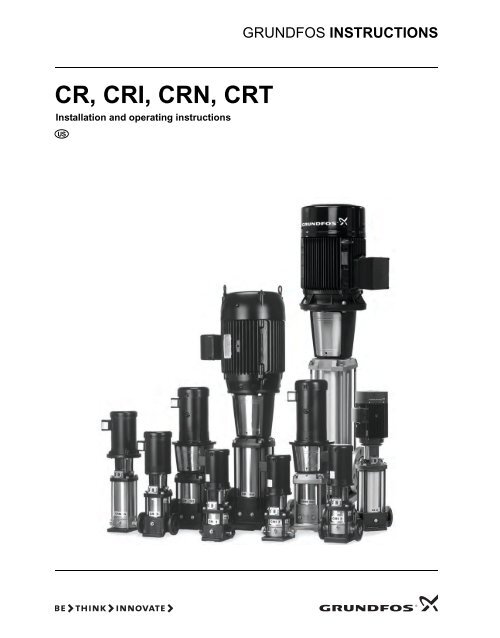
GRUNDFOS INSTRUCTIONS<br />
<strong>CR</strong>, <strong>CR</strong>I, <strong>CR</strong>N, <strong>CR</strong>T<br />
Installation and operating instructions
LIMITED WARRANTY<br />
Products manufactured by GRUNDFOS PUMPS CORPORATION (Grundfos) are warranted<br />
to the original user only to be free of defects in material and workmanship for a period of<br />
24 months from date of installation, but not more than 30 months from date of manufacture.<br />
Grundfos' liability under this warranty shall be limited to repairing or replacing at Grundfos'<br />
option, without charge, F.O.B. Grundfos' factory or authorized service station, any product<br />
of Grundfos' manufacture. Grundfos will not be liable for any costs of removal, installation,<br />
transportation, or any other charges which may arise in connection with a warranty claim.<br />
Products which are sold but not manufactured by Grundfos are subject to the warranty<br />
provided by the manufacturer of said products and not by Grundfos' warranty. Grundfos will<br />
not be liable for damage or wear to products caused by abnormal operating conditions,<br />
accident, abuse, misuse, unauthorized alteration or repair, or if the product was not installed<br />
in accordance with Grundfos' printed installation and operating instructions.<br />
To obtain service under this warranty, the defective product must be returned to the<br />
distributor or dealer of Grundfos' products from which it was purchased together with proof<br />
of purchase and installation date, failure date, and supporting installation data. Unless<br />
otherwise provided, the distributor or dealer will contact Grundfos or an authorized service<br />
station for instructions. Any defective product to be returned to Grundfos or a service station<br />
must be sent freight prepaid; documentation supporting the warranty claim and/or a Return<br />
Material Authorization must be included if so instructed.<br />
GRUNDFOS WILL NOT BE LIABLE FOR ANY INCIDENTAL OR CONSEQUENTIAL<br />
DAMAGES, LOSSES, OR EXPENSES ARISING FROM INSTALLATION, USE, OR ANY<br />
OTHER CAUSES. THERE ARE NO EXPRESS OR IMPLIED WARRANTIES, INCLUDING<br />
MERCHANTABILITY OR FITNESS FOR A PARTICULAR PURPOSE, WHICH EXTEND<br />
BEYOND THOSE WARRANTIES DES<strong>CR</strong>IBED OR REFERRED TO ABOVE.<br />
Some jurisdictions do not allow the exclusion or limitation of incidental or consequential<br />
damages and some jurisdictions do not allow limit actions on how long implied warranties<br />
may last. Therefore, the above limitations or exclusions may not apply to you. This warranty<br />
gives you specific legal rights and you may also have other rights which vary from<br />
jurisdiction to jurisdiction.<br />
2
<strong>CR</strong>, <strong>CR</strong>I, <strong>CR</strong>N, <strong>CR</strong>T<br />
Installation and operating instructions 5<br />
3
CONTENTS<br />
Page<br />
Shipment inspection 5<br />
Understanding nameplate data 6<br />
Understanding codes 7<br />
Confirming proper application 8<br />
Checking operating conditions 8<br />
Installing the pump 10<br />
Pump location 10<br />
Foundation 10<br />
Pump mounting 11<br />
Check valves 13<br />
Electrical 14<br />
Motor 14<br />
Starting the pump the first time 14<br />
Preventative pump maintenance 16<br />
Maintaining the pump’s motor 16<br />
Motor Lubrication 16<br />
Lubrication Procedure 17<br />
Replacing the motor 17<br />
Parts List 19<br />
Spare Parts 19<br />
Preliminary electrical tests 20<br />
Startup for Cool-Top® 21<br />
Diagnosing specific problems 22<br />
Worksheet for three-phase motors 24<br />
Warning<br />
Electrical Work: All electrical work should be<br />
performed by a qualified electrician in<br />
accordance with the latest edition of the National<br />
Electrical Code, local codes and regulations.<br />
Warning<br />
Shock Hazard: A faulty motor or wiring can cause<br />
electrical shock that could be fatal, whether<br />
touched directly or conducted through standing<br />
water. For this reason, proper grounding of the<br />
pump to the power supply’s grounding terminal<br />
is required for safe installation and operation.<br />
In all installations, the above-ground metal<br />
plumbing should be connected to the power<br />
supply ground as described in Article 250-80 of<br />
the National Electrical Code.<br />
1. General<br />
The <strong>CR</strong> range is based on the inline multistage centrifugal pump<br />
first pioneered by Grundfos. <strong>CR</strong> is available in four basic<br />
materials and over one million configurations. <strong>CR</strong> is suitable for<br />
pumping water and water-like liquids in industry, petrochemical,<br />
water treatment, commercial buildings, and many other<br />
applications. Some of <strong>CR</strong>’s outstanding characteristics are:<br />
• superior efficiency<br />
• reliability<br />
• ease of maintenance<br />
• compact size and small footprint<br />
• quiet operation.<br />
2. Shipment inspection<br />
Examine the components carefully to make sure no damage has<br />
occurred to the pump during shipment. Care should be taken to<br />
ensure the pump is NOT dropped or mishandled.<br />
2.1 Ensure you have the right pump<br />
Read the pump nameplate to make sure that it is the one you<br />
ordered.<br />
• <strong>CR</strong><br />
Centrifugal pump with standard cast iron and 304 stainless<br />
steel construction<br />
• <strong>CR</strong>I<br />
Centrifugal pump; all parts in contact with water are 304<br />
stainless steel construction<br />
• <strong>CR</strong>N<br />
Centrifugal pump; all parts in contact with water are 316<br />
stainless steel construction<br />
• <strong>CR</strong>T<br />
Centrifugal pump; all parts in contact with water are titanium<br />
construction<br />
• <strong>CR</strong>E<br />
Centrifugal pump with a Grundfos MLE VFD motor attached.<br />
2.2 Checking the condition of the pump<br />
The shipping carton in which your pump arrived is specially<br />
designed around your pump during production to prevent damage<br />
during shipment. As a precaution, the pump should remain in the<br />
carton until you are ready to install it. Examine the pump for any<br />
damage that may have occurred during shipping. Examine any<br />
other parts of the shipment as well for any visible damage.<br />
Note: If the pump is shipped as a complete unit (motor attached<br />
to pump end), the position of the coupling (that connects the<br />
pump shaft to the motor shaft) is set at factory specifications. No<br />
adjustment is required. If the unit is delivered as a pump end only,<br />
follow the adjustment procedures in the section on replacing the<br />
motor.<br />
Pump without Motor (<strong>CR</strong>(I)(N) 1s, 1, 3, 5, 10, 15, and 20 Only):<br />
If you purchased a pump without a motor, the shaft seal has been<br />
set by the factory. Do not loosen the three set screws on the shaft<br />
seal when attaching the motor.<br />
Pump without Motor (<strong>CR</strong>(N) 32, 45, 64, 90, 120, and 150 Only):<br />
If you purchased a pump without a motor, you must install the<br />
seal. The seal is protected in its own sub boxing within the pump<br />
packaging crate. To protect the shaft and bearings during<br />
shipment, a shaft holder protective device is used. This device<br />
must be removed prior to installation of the seal. Read the seal<br />
installation instructions which are included in the pump package.<br />
2.3 Verifying electrical requirements<br />
Verification of the electrical supply should be made to be certain<br />
the voltage, phase and frequency match that of the pump motor.<br />
The proper operating voltage and other electrical information can<br />
be found on the motor nameplate. These motors are designed to<br />
run on –10 % / + 10 % of the nameplate-rated voltage. For dualvoltage<br />
motors, the motor should be internally connected to<br />
operate on the voltage closest to the 10% rating, i.e., a 208<br />
voltage motor wired per the 208 volt connection diagram. The<br />
wiring connection diagram can be found on either a plate<br />
attached to the motor or on a diagram inside the terminal box<br />
cover. If voltage variations are larger than –10 % / + 10 %, do not<br />
operate the pump.<br />
5
3. Understanding nameplate data<br />
Type key<br />
<strong>CR</strong>, <strong>CR</strong>I, <strong>CR</strong>N 1s, 1, 3, 5, 10, 15, and 20<br />
Example<br />
Type range: <strong>CR</strong> 3 -10 A FG A E HQQE<br />
<strong>CR</strong>, <strong>CR</strong>I,<br />
Rated flow rate in [m 3 /h] (x 5gpm)<br />
Number of impellers<br />
Code for pump version<br />
Code for pipe connection<br />
Code for materials<br />
Code for rubber parts<br />
Code for shaft seal<br />
<strong>CR</strong>T 2, 4, 8, and 16<br />
Example<br />
Type range: <strong>CR</strong>T 16 -30 /2 U G A AUUE<br />
<strong>CR</strong>T<br />
Rated flow rate in [m 3 /h] (x 5gpm)<br />
Number of stages x 10<br />
Code for impellers (used only if the pump<br />
has fewer impellers than stages)<br />
Code for pump version<br />
Code for pipe connection<br />
Code for materials<br />
Code for shaft seal and rubber parts<br />
11<br />
3<br />
5<br />
7<br />
Fig. 1<br />
Q<br />
P<br />
1<br />
2<br />
4<br />
6<br />
8<br />
9 10<br />
Nameplate<br />
GPM<br />
H<br />
FEET<br />
TM04 3895 0309<br />
1. Type designation<br />
2. Model, material<br />
number, production<br />
number<br />
3. Head in feet at<br />
nominal flow<br />
4. Nominal motor hp<br />
5. Head at zero flow<br />
6. Rated rpm<br />
7. Nominal flow<br />
8. Rated frequency<br />
9. Maximum pressure<br />
and maximum fluid<br />
temperature<br />
10. Direction of rotation<br />
11. Production country<br />
RPM<br />
HP N<br />
PSI °F max<br />
TM04 3894 0309<br />
<strong>CR</strong>, <strong>CR</strong>N 32, 45, 64, 90, 120, and 150<br />
Example<br />
Type C 32 -2 -1 U G A E KUBE<br />
<strong>CR</strong>, <strong>CR</strong>N<br />
Rated flow rate in [m 3 /h] (x 5gpm)<br />
Number of impellers<br />
Number of reduced diameter impellers<br />
Code for pump version<br />
Code for pipe connection<br />
Code for materials<br />
Code for rubber pump parts<br />
Code for shaft seal<br />
Fig. 2<br />
Designated<br />
Model<br />
(eg.ABCD)<br />
Fig. 3<br />
Nameplate<br />
A 12345678 P1 01 41<br />
Material<br />
Number<br />
Model key<br />
Production<br />
Company<br />
Last two digits<br />
of production year<br />
Production week number(01 52)<br />
TM04 3904 0409<br />
6
3.1 Understanding codes<br />
Example<br />
Pump version: U FGJ A E HQQE<br />
A *Basic pump version<br />
U *NEMA Version Pump<br />
B<br />
Oversize motor,<br />
one flange size bigger<br />
F<br />
<strong>CR</strong> pump for high<br />
temperatures (Cool-Top®)<br />
Shaft seal<br />
H Horizontal version A O-ring with fixed driver<br />
HS<br />
High pressure pump with<br />
B Rubber bellows seal<br />
over-synchronous speed and<br />
reversed direction of rotation<br />
D O-ring seal, balanced<br />
I Different pressure rating<br />
Cartridge seal with<br />
E<br />
O-ring<br />
K Low NPSH<br />
Balanced cartridge<br />
H<br />
seal with O-ring<br />
M Magnetic drive<br />
Cartridge shaft seal<br />
P Undersize motor<br />
K<br />
with metal bellows<br />
R<br />
Horizontal version with<br />
Double seal, back to<br />
O<br />
bearing bracket<br />
back<br />
High pressure pump with<br />
P Double seal, tandem<br />
SF reversed chamber stack and<br />
O-ring seal with<br />
direction of rotation<br />
R<br />
reduced face<br />
T<br />
Oversize motor,<br />
two flange sizes bigger<br />
X<br />
Special version<br />
H Q Q E<br />
X **Special version<br />
Carton, synthetic<br />
B<br />
resin-impregnated<br />
Pipe connection<br />
Cemented tungsten<br />
A Oval flange<br />
H<br />
carbine, embedded<br />
B NTP thread Q Silicon carbide<br />
C Clamp coupling<br />
Cemented tungsten<br />
U<br />
carbide<br />
CA FlexiClamp<br />
CX TriClamp E EPDM<br />
F DIN flange F FXM (Flouraz®)<br />
G ANSI flange K FFKM (Kalraz®)<br />
J JIS flange V FKM (Viton®)<br />
N Changed diameter of ports<br />
O<br />
P<br />
X<br />
Externally threaded, union<br />
PJE coupling<br />
Special version<br />
* In August 2003 the NEMA pump code was<br />
discontinued for all material numbers created<br />
by GRUNDFOS manufacturing companies in<br />
North America. The NEMA version pump code will<br />
still remain in effect for existing material numbers.<br />
NEMA version pumps built in North America after<br />
this change will have either an A or U as the pump<br />
version code depending on the date the material<br />
number was created.<br />
Materials<br />
A Basic version<br />
A<br />
Carbon-filled graphite PTFE<br />
(bearings)<br />
G Stainless steel parts of 316 SS<br />
GI Base plate and flanges of 316 SS<br />
I Stainless steel parts of 304 SS ** If a pump incorporates more than two pump<br />
versions, the code for the pump version is X.<br />
II Base plate and flange of 304 SS<br />
X also indicates special pump versions not<br />
listed above.<br />
K<br />
S<br />
T<br />
X<br />
Bronze (bearings)<br />
SiC bearing ring + PTFE neck<br />
ring (only <strong>CR</strong>, <strong>CR</strong>N 32 to 90<br />
Titanium<br />
Special version<br />
Code for rubber parts<br />
E EPDM<br />
F FXM (Flouraz®)<br />
K FFKM (Kalrez®)<br />
V FKM (Viton®)<br />
7
4. Confirming proper application<br />
Compare the pump’s nameplate data or its performance curve<br />
with the application in which you plan to install it. Will it perform<br />
the way you want it to perform Also, make sure the application<br />
falls within the following limits.<br />
Type<br />
Designed to pump<br />
<strong>CR</strong><br />
Hot and chilled water, boiler feed, condensate<br />
return, glycols and solar thermal fluids.<br />
Deionized, demineralized and distilled water.<br />
<strong>CR</strong>I/<strong>CR</strong>N<br />
Brackish water and other liquids unsuitable for<br />
contact with iron or copper alloys. (Consult<br />
manufacturer for specific liquid compatibilities.)<br />
<strong>CR</strong>N-SF<br />
High pressure washdown, reverse osmosis, or other<br />
high pressure applications.<br />
<strong>CR</strong>T<br />
Salt water, chloride based fluids and fluids approved<br />
for titanium.<br />
5. Checking operating conditions<br />
5.1 Fluid temperatures<br />
Pump<br />
<strong>CR</strong>(I)(N) 1s, 3, 5, 10, 15, and 20<br />
*<strong>CR</strong>(N) 32, 45, 64, and 90<br />
*<strong>CR</strong>(N) 120 and 150<br />
(up to 60 hp)<br />
<strong>CR</strong>(N) 120 and 150<br />
(75 and 100 hp)<br />
<strong>CR</strong>T 2, 4, 8, 16<br />
<strong>CR</strong>N-SF<br />
with Cool-Top<br />
Fluid<br />
Temperatures<br />
–4 to +248 °F<br />
(–20 to +120 °C)<br />
–22 to +248 °F<br />
(–30 to +120 °C)<br />
–22 to +248 °F<br />
(–30 to +120 °C)<br />
+32 to +248 °F<br />
(0 to +120 °C)<br />
–4 to +248 °F<br />
(–20 to +120 °C)<br />
–4 to +221 °F<br />
(–15 to +105 °C)<br />
up to +356 °F<br />
(+180 °C)<br />
All motors are designed for continuous duty in +104 °F (+40 °C)<br />
ambient air conditions. For higher ambient temperature<br />
conditions consult Grundfos.<br />
* xUBE Shaft Seals are recommended for temperatures above<br />
+200 °F. Pumps with hybrid shaft KUHE seals can only operate<br />
up to +200 °F (+90 °C). Pumps with xUUE shaft seals can be<br />
operated down to –40 °F (–40 °C) (where “x” is the seal type).<br />
5.2 Minimum inlet pressures<br />
All <strong>CR</strong>, <strong>CR</strong>I, <strong>CR</strong>N<br />
<strong>CR</strong>N-SF<br />
5.3 Maximum inlet pressures<br />
Pump Type/<br />
Connection<br />
50 Hz<br />
Stages<br />
NPSHR + 2 feet<br />
29 psi (2 bar)<br />
60 Hz<br />
Stages<br />
Max.<br />
psi/bar<br />
<strong>CR</strong>, <strong>CR</strong>I, <strong>CR</strong>N 1s 2 to 36 2 to 36 145 / 10<br />
27 217 / 15<br />
<strong>CR</strong>, <strong>CR</strong>I, <strong>CR</strong>N 1 2 to 36 2 to 36 145 / 10<br />
27 217 / 15<br />
<strong>CR</strong>, <strong>CR</strong>I, <strong>CR</strong>N 3 2 to 29 2 to 15 145 / 10<br />
31 to 36 17 to 25 217 / 15<br />
<strong>CR</strong>, <strong>CR</strong>I, <strong>CR</strong>N 5 3 to 16 2 to 9 145 / 10<br />
18 to 36 10 to 24 217 / 15<br />
<strong>CR</strong>, <strong>CR</strong>I, <strong>CR</strong>N 10 1 to 6 1 to 5 116 / 8<br />
7 to 22 6 to 18 145 / 10<br />
<strong>CR</strong>, <strong>CR</strong>I, <strong>CR</strong>N 15 1 to 3 1 to 2 116 / 8<br />
4 to 17 3 to 12 145 / 10<br />
<strong>CR</strong>, <strong>CR</strong>I, <strong>CR</strong>N 20 1 to 3 1 116 / 8<br />
4 to 17 2 to 10 145 / 10<br />
<strong>CR</strong>, <strong>CR</strong>N 32 1-1 to 4 1-1 to 2 58 / 4<br />
5-2 to 10 3-2 to 6 145 / 10<br />
11 to 14 7-2 to 11-2 217 / 15<br />
<strong>CR</strong>, <strong>CR</strong>N 45 1-1 to 2 1-1 to 1 58 / 4<br />
3-2 to 5 2-2 to 3 145 / 10<br />
6-2 to 13-2 4-2 to 8-1 217 / 15<br />
<strong>CR</strong>, <strong>CR</strong>N 64 1-1 to 2-2 1-1 58 / 4<br />
2-1 to 4-2 1 to 2-1 145 / 10<br />
4-1 to 8-1 2 to 5-2 217 / 15<br />
<strong>CR</strong>, <strong>CR</strong>N 90 1-1 to 1 58 / 4<br />
2-2 to 3-2 1-1 to 1 145 / 10<br />
3 to 6 2-2 to 4-1 217 / 15<br />
<strong>CR</strong>, <strong>CR</strong>N 120 1 to 2-1 1-1 to 1 145 / 10<br />
2 to 5-1 2-2 to 3 217 / 15<br />
6-1 to 7 4-1 to 5-2 290 / 20<br />
<strong>CR</strong>, <strong>CR</strong>N 150 1-1 to 1 1-1 145 / 10<br />
2-1 to 4-1 1 to 2 217 / 15<br />
5-2 to 6 3-2 to 4-2 290 / 20<br />
<strong>CR</strong>T 2 2 to 11 2 to 6 145 / 10<br />
13 to 26 7 to 18 217 / 15<br />
<strong>CR</strong>T 4 1 to 12 1 to 7 145 / 10<br />
14 to 22 8 to 16 217 / 15<br />
<strong>CR</strong>T 8 1 to 20 1 to 16 145 / 10<br />
<strong>CR</strong>T 16 2 to 16 2 to 10 145 / 10<br />
<strong>CR</strong>N-SF all all 72 / 5*<br />
362 / 25**<br />
* while pump is off or during start-up<br />
** during operation<br />
8
5.4 Maximum operating pressures<br />
at +250 °F (194 °F for <strong>CR</strong>N-SF)<br />
Pump type/<br />
connection<br />
50 Hz<br />
stages<br />
60 Hz<br />
stages<br />
Max.<br />
psi/bar<br />
<strong>CR</strong>, <strong>CR</strong>I, <strong>CR</strong>N 1s<br />
Oval flange 1 to 23 1 to 17 232 / 16<br />
FGJ, PJE 1 to 36 1 to 27 362 / 25<br />
<strong>CR</strong>, <strong>CR</strong>I, <strong>CR</strong>N 1<br />
Oval flange 1 to 23 1 to 17 232 / 16<br />
FGJ, PJE 1 to 36 1 to 27 362 / 25<br />
<strong>CR</strong>, <strong>CR</strong>I, <strong>CR</strong>N 3<br />
Oval flange 1 to 23 1 to 17 232 / 16<br />
FGJ, PJE 1 to 36 1 to 27 362 / 25<br />
<strong>CR</strong>, <strong>CR</strong>I, <strong>CR</strong>N 5<br />
Oval flange 1 to 22 1 to 16 232 / 16<br />
FGJ, PJE 1 to 36 1 to 24 362 / 25<br />
<strong>CR</strong>, <strong>CR</strong>I 10<br />
Oval flange <strong>CR</strong> 1 to 6 145 / 10<br />
Oval flange, <strong>CR</strong>I 1 to 16 1 to 10 232 / 16<br />
FGJ, GJ, PJE 1 to 16 1 to 10 232 / 16<br />
FGJ, GJ, PJE 17 to 22 12 to 17 362 / 25<br />
<strong>CR</strong>N 10<br />
All 1 to 22 1 to 17 362 / 25<br />
<strong>CR</strong>, <strong>CR</strong>I 15<br />
Oval flange 1 to 7 1 to 5 145 / 10<br />
FGJ, GJ, PJE 1 to 10 1 to 8 232 / 16<br />
FGJ, GJ, PJE 12 to 17 9 to 12 362 / 25<br />
<strong>CR</strong>N 15<br />
All 1 to 17 1 to 12 362 / 25<br />
<strong>CR</strong>, <strong>CR</strong>I 20<br />
Oval flange 1 to 7 1 to 5 145 / 10<br />
FGJ, GJ, PJE 1 to 10 1 to 7 232 / 16<br />
FGJ, GJ, PJE 12 to 17 8 to 10 362 / 25<br />
<strong>CR</strong>N 20<br />
All 1 to 17 1 to 10 362 / 25<br />
<strong>CR</strong>, <strong>CR</strong>N 32<br />
<strong>CR</strong>, <strong>CR</strong>N 45<br />
<strong>CR</strong>, <strong>CR</strong>N 64<br />
<strong>CR</strong>, <strong>CR</strong>N 90<br />
<strong>CR</strong>, <strong>CR</strong>N 120<br />
<strong>CR</strong>, <strong>CR</strong>N 150<br />
1-1 to 7 1-1 to 5 232 / 16<br />
8-2 to 14 6-2 to 11-2 435 / 30<br />
1-1 to 5 1-1 to 4-2 232 / 16<br />
6-2 to 13-2 4-2 to 8-1 435 / 30<br />
1-1 to 5 1-1 to 3 232 / 16<br />
6-2 to 8-1 4-2 to 5-2 435 / 30<br />
1-1 to 4 1-1 to 3 232 / 16<br />
5-2 to 6 4-2 to 4-1 435 / 30<br />
1-1 to 3 232 / 16<br />
1-1 to 5-2 4-2 to 5-2 435 / 30<br />
1-1 to 3 232 / 16<br />
1-1 to 4-2 4-1 to 4-2 435 / 30<br />
<strong>CR</strong>T 2 2 to 26 2 to 18 305 / 21<br />
<strong>CR</strong>T 4 1 to 22 1 to 16 305 / 21<br />
<strong>CR</strong>T 8 1 to 12 1 to 8 232 / 16<br />
14 to 20 10 to 16 362 / 25<br />
<strong>CR</strong>T 16 1 to 8 1 to 8 232 / 16<br />
10 to 16 10 to 12 362 / 25<br />
Consult Grundfos for other working conditions.<br />
9
6. Installing the pump<br />
Warning<br />
Do not energize pump until properly installed.<br />
6.1 Pump location<br />
The pump should be located in a dry, well-ventilated area which is<br />
not subject to freezing or extreme variation in temperature.<br />
Care must be taken to ensure the pump is mounted at least<br />
6 inches (150 mm) clear of any obstruction or hot surfaces.<br />
The motor requires an adequate air supply to prevent overheating<br />
and adequate vertical space to remove the motor for repair.<br />
For open systems requiring suction lift the pump should be<br />
located as close to the water source as possible to reduce piping<br />
losses.<br />
6.2 Foundation<br />
Concrete or similar foundation material should be used to provide<br />
a secure, stable mounting base for the pump.<br />
See table of bolt hole center line dimensions for the various pump<br />
types.<br />
Secure the pump to the foundation using all four bolts and shim<br />
pump base to assure the pump is vertical and all four pads on the<br />
base are properly supported (uneven surfaces can result in pump<br />
base breakage when mounting bolts are tightened).<br />
Fig. 4<br />
Pump position<br />
The pump can be installed vertically or horizontally; see fig. 4.<br />
Ensure that an adequate supply of cool air reaches the motor<br />
cooling fan. The motor must never fall below the horizontal plane.<br />
Arrows on the pump base show the direction of flow of liquid<br />
through the pump.<br />
To minimize possible noise from the pump, it is advisable to fit<br />
expansion joints on either side of the pump and anti-vibration<br />
mountings between the foundation and the pump.<br />
Note: Care should be taken to ensure that the vent plug is<br />
located in the uppermost position.<br />
Isolating valves should be fitted either side of the pump to avoid<br />
draining the system if the pump needs to be cleaned, repaired or<br />
replaced.<br />
TM04 3906 0409<br />
4 x ø<br />
L<br />
L<br />
1<br />
2<br />
B<br />
B<br />
1<br />
2<br />
TM00 2256<br />
Pump type<br />
L1 L2 B1 B2 ø<br />
in mm in mm in mm in mm in mm<br />
<strong>CR</strong> 1s, 1, 3, 5 3 15/16 100 5 11/16 145 7 1/16 180 8 11/16 220 1/2 13<br />
<strong>CR</strong>I, <strong>CR</strong>N 1s 1, 3, 5 3 15/16 100 5 7/8 150 7 1/16 180 8 11/16 220 1/2 13<br />
<strong>CR</strong> 10, 15, 20 5 1/8 130 6 15/16 176 8 7/16 215 10 1/16 256 9/16 13.5<br />
<strong>CR</strong>N 10, 15, 20 5 1/8 130 7 7/8 200 8 7/16 215 9 3/4 248 1/2 13<br />
<strong>CR</strong> 32 6 11/16 170 8 3/4 223 9 7/16 240 11 3/4 298 9/16 14<br />
<strong>CR</strong>N 32 6 11/16 170 8 7/8 226 9 7/16 240 11 3/4 298 9/16 14<br />
<strong>CR</strong> 45,64 7 1/2 190 9 3/4 248 10 1/2 266 13 1/16 331 9/16 14<br />
<strong>CR</strong>N 45,64 7 1/2 190 9 7/8 251 10 1/2 266 13 1/16 331 9/16 14<br />
<strong>CR</strong>(N) 90 7 13/16 199 10 1/4 261 11 280 13 11/16 348 9/16 14<br />
<strong>CR</strong>(N) 120, 150 10 13/16 275 13 9/16 344 14 15/16 380 18 9/16 472 11/16 18<br />
10
6.3 Pump mounting<br />
6.3.1 Recommended installation torques<br />
Model<br />
<strong>CR</strong>, <strong>CR</strong>I, <strong>CR</strong>N<br />
1s/1/3/5, and<br />
<strong>CR</strong>T 2/4<br />
<strong>CR</strong>, <strong>CR</strong>I,<br />
<strong>CR</strong>N 10/15/20, and<br />
<strong>CR</strong>T 8/16<br />
<strong>CR</strong>, <strong>CR</strong>N<br />
32/45/64/90/<br />
120/150<br />
6.4 Suction pipe<br />
Warning<br />
<strong>CR</strong>, <strong>CR</strong>I, <strong>CR</strong>N pumps are shipped with covered<br />
suction and discharge. The covers must be<br />
removed before the final pipe flange to pump<br />
connections are made.<br />
Recommended<br />
foundation torque<br />
(ft - lbs)<br />
Recommended<br />
flange torque<br />
(ft - lbs)<br />
30 37 - 44<br />
37 44 - 52<br />
52 52 - 59<br />
The suction pipe should be adequately sized and run as straight and<br />
short as possible to keep friction losses to a minimum (minimum of<br />
four pipe diameters straight run prior to the suction flange). Avoid<br />
using unnecessary fittings, valves or accessory items. Butterfly or<br />
gate valves should only be used in the suction line when it is<br />
necessary to isolate a pump because of a flooded suction condition.<br />
This would occur if the water source is above the pump; see fig. 5<br />
and fig. 6. Flush piping prior to pump installation to remove loose<br />
debris.<br />
Reservoir<br />
6.5 Minimum suction pipe sizes<br />
The following recommended suction pipe sizes are the smallest<br />
sizes which should be used with any specific <strong>CR</strong> pump type.<br />
The suction pipe size should be verified with each installation to<br />
ensure good pipe practices are being observed and excess<br />
friction losses are not encountered.<br />
High temperatures may require larger diameter pipes to reduce<br />
friction and improve NPHSA.<br />
Model<br />
<strong>CR</strong>(I)(N) 1s, 1, 3; <strong>CR</strong>T 2 1"<br />
<strong>CR</strong>(I)(N) 5;<br />
<strong>CR</strong>T 4<br />
<strong>CR</strong>(I)(N) 10, 15, 20;<br />
<strong>CR</strong>T 8, 16<br />
1-1/4"<br />
2"<br />
<strong>CR</strong>(N) 32 2-1/2"<br />
<strong>CR</strong>(N) 45 3"<br />
<strong>CR</strong>(N) 64, 90 4"<br />
<strong>CR</strong>(N) 120, 150 5"<br />
Min. suction pipe size<br />
Nominal diameter<br />
sch 40 pipe<br />
Nominal diameter<br />
sch 40 pipe<br />
Nominal diameter<br />
sch 40 pipe<br />
Nominal diameter<br />
sch 40 pipe<br />
Nominal diameter<br />
sch 40 pipe<br />
Nominal diameter<br />
sch 40 pipe<br />
Nominal diameter<br />
sch 40 pipe<br />
6.6 Discharge piping<br />
It is suggested that a check valve and isolation valve be installed<br />
in the discharge pipe.<br />
Pipe, valves and fittings should be at least the same diameter as<br />
the discharge pipe or sized in accordance with good piping<br />
practices to reduce excessive fluid velocities and pipe friction<br />
losses.<br />
Note: Pipe, valves and fittings must have a pressure rating equal<br />
to or greater than the maximum system pressure.<br />
Butterfly<br />
Valve<br />
Fig. 5<br />
Check<br />
Valve<br />
Flooded suction<br />
Butterfly<br />
Valve<br />
Expansion Joint<br />
Check<br />
Valve<br />
Eccentric<br />
Reducer<br />
Butterfly<br />
Valve<br />
Strainer<br />
TM04 3925 0409<br />
Before the pump is installed it is recommended that the discharge<br />
piping be pressure checked to at least the maximum pressure the<br />
pump is capable of generating or as required by codes or local<br />
regulations.<br />
Whenever possible, avoid high pressure loss fittings, such as<br />
elbows or branch tees directly on either side of the pump. The<br />
piping should be adequately supported to reduce thermal and<br />
mechanical stresses on the pump.<br />
Good installation practice recommends the system be thoroughly<br />
cleaned and flushed of all foreign materials and sediment prior to<br />
pump installation. Furthermore, the pump should never be<br />
installed at the lowest point of the system due to the natural<br />
accumulation of dirt and sediment. If there is excessive sediment<br />
or suspended particles present, it is advised a strainer or filter be<br />
used. Grundfos recommends that pressure gauges be installed<br />
on inlet and discharge flanges or in pipes to check pump and<br />
system performance.<br />
Suction<br />
Pipe<br />
Reservior<br />
Foot<br />
Valve<br />
TM04 3910 0409<br />
Warning<br />
To avoid problems with waterhammer, fast<br />
closing valves must not be used in <strong>CR</strong>N-SF<br />
applications.<br />
Fig. 6<br />
Suction lift*<br />
*The suction pipe should have a fitting on it for priming.<br />
<strong>CR</strong>N-SF pumps cannot be used for suction lift.<br />
11
6.7 Bypass orifice<br />
A bypass should be installed in the discharge pipe if there is any<br />
possibility the pump may operate against a closed valve in the<br />
discharge line. Flow through the pump is required to ensure<br />
adequate cooling and lubrication of the pump is maintained. See<br />
6.9 Minimum continuous duty flow rates for minimum flow rates.<br />
Elbows should be a minimum of 12” from the orifice discharge to<br />
prevent erosion.<br />
6.8 Nozzle loads<br />
If not all loads reach the maximum permissible value stated in the<br />
forces and moments tables included here with fig. 10, one of<br />
these values may exceed the normal limit. Contact Grundfos for<br />
further information.<br />
TM04 3926 0409<br />
Fig. 7<br />
Recommended bypass arrangement<br />
Y-direction:<br />
Z-direction:<br />
X-direction:<br />
Direction of chamber stack<br />
90 ° from inlet/outlet<br />
Inlet/outlet<br />
TM04 0346<br />
Fig. 10 Nozzle forces and moments<br />
Fig. 8<br />
Optional bypass arrangement<br />
TM04 3909 0409<br />
Flange<br />
<strong>CR</strong>, <strong>CR</strong>I,<br />
<strong>CR</strong>N<br />
Y-direction<br />
[lb]<br />
Forces<br />
Z-direction<br />
[lb]<br />
X-direction<br />
[lb]<br />
1-1/4" 1s to 5 171 263 175<br />
2"<br />
10, 15<br />
and 20<br />
303 371 337<br />
2-1/2" 32 382 466 422<br />
3" 45 461 562 506<br />
4" 64 and 90 607 753 674<br />
5" & 6"<br />
120 and<br />
150<br />
607 753 674<br />
Nipple<br />
Orifice<br />
By Pass Line<br />
Fig. 9 Optional bypass arrangement for <strong>CR</strong>(N) 32, 45, 64,<br />
and <strong>CR</strong> 90, 120, and 150 only<br />
TM04 3924 0409<br />
Flange<br />
<strong>CR</strong>, <strong>CR</strong>I,<br />
<strong>CR</strong>N<br />
Y-direction<br />
[ft-lb]<br />
Moments<br />
Z-direction<br />
[ft-lb]<br />
X-direction<br />
[ft-lb]<br />
1-1/4" 1s to 5 605 715 900<br />
2"<br />
10, 15<br />
and 20<br />
738 848 1,033<br />
2-1/2" 32 793 904 1,106<br />
3" 45 848 959 1,180<br />
4" 64 and 90 922 1,069 1,291<br />
5" & 6"<br />
120 and<br />
150<br />
922 1,069 1,291<br />
12
6.9 Minimum continuous duty flow rates<br />
Pump Type<br />
min °F to 176 °F<br />
(min °C to 80 °C)<br />
* Grundfos Cool-Top® is only available in the following pump types.<br />
at 210°F<br />
(at 99°C)<br />
at 248°F<br />
(at 120°C)<br />
at 356°F<br />
(at 180°C)<br />
<strong>CR</strong>, <strong>CR</strong>I, <strong>CR</strong>N 1s 0.5 0.7 1.2 1.2*<br />
<strong>CR</strong>, <strong>CR</strong>I, <strong>CR</strong>N 1 0.9 1.3 2.3 2.3*<br />
<strong>CR</strong>, <strong>CR</strong>I, <strong>CR</strong>N 3 1.6 2.4 4.0 4.0*<br />
<strong>CR</strong>, <strong>CR</strong>I, <strong>CR</strong>N 5 3.0 4.5 7.5 7.5*<br />
<strong>CR</strong>, <strong>CR</strong>I, <strong>CR</strong>N 10 5.5 8.3 14 14*<br />
<strong>CR</strong>, <strong>CR</strong>I, <strong>CR</strong>N 15 9.5 14 24 24*<br />
<strong>CR</strong>, <strong>CR</strong>I, <strong>CR</strong>N 20 11 17 28 28*<br />
<strong>CR</strong>, <strong>CR</strong>N 32 14 21 35 35*<br />
<strong>CR</strong>, <strong>CR</strong>N 45 22 33 55 55*<br />
<strong>CR</strong>, <strong>CR</strong>N 64 34 51 85 85*<br />
<strong>CR</strong>, <strong>CR</strong>N 90 44 66 110 110*<br />
<strong>CR</strong>, <strong>CR</strong>N 120 60 90 N/A N/A<br />
<strong>CR</strong>, <strong>CR</strong>N 150 75 115 N/A N/A<br />
<strong>CR</strong>T 2 1.3 2.0 3.3 N/A<br />
<strong>CR</strong>T 4 3.0 4.5 7.5 N/A<br />
<strong>CR</strong>T 8 4.0 6.0 10 N/A<br />
<strong>CR</strong>T 16 8.0 0.7 20 N/A<br />
Pump Type <strong>CR</strong> 1s <strong>CR</strong> 1 <strong>CR</strong> 3 <strong>CR</strong> 5 <strong>CR</strong> 10 <strong>CR</strong> 15 <strong>CR</strong> 20 <strong>CR</strong> 32 <strong>CR</strong> 45 <strong>CR</strong> 64 <strong>CR</strong> 90<br />
Standard (<strong>CR</strong>) • • • •<br />
I Version (<strong>CR</strong>I) • • • • • • •<br />
N Version (<strong>CR</strong>N) • • • • • • • • • • •<br />
6.10 Check valves<br />
A check valve may be required on the discharge side of the pump<br />
to prevent the pump’s inlet pressure from being exceeded.<br />
For example, if a pump with no check valve is stopped because<br />
there is no demand on the system (all valves are closed), the high<br />
system pressure on the discharge side of the pump will “find” its<br />
way back to the inlet of the pump.<br />
If the system pressure is greater than the pump’s maximum inlet<br />
pressure rating, the limits of the pump will be exceeded and a<br />
check valve needs to be fitted on the discharge side of the pump<br />
to prevent this condition. This is especially critical for <strong>CR</strong>N-SF<br />
applications because of the very high discharge pressures<br />
involved. As a result, most <strong>CR</strong>N-SF installations require a check<br />
valve on the discharge piping.<br />
6.11 Temperature rise<br />
It may sometimes be necessary to stop the flow through a pump<br />
during operation.<br />
At shut-off, the power to the pump is transferred to the pumped<br />
liquid as head, causing a temperature rise in the liquid.<br />
The result is risk of excess heating of and consequent damage to<br />
the pump. The risk depends on the temperature of the pumped<br />
liquid and for how long the pump is operating without flow; see<br />
the following temperature rise chart.<br />
Pump type<br />
Time for temperature rise<br />
of 18 °F (10 °C)<br />
Seconds<br />
Minutes<br />
<strong>CR</strong> 1s, 1, 3 210 3.5<br />
<strong>CR</strong> 5 240 4.0<br />
<strong>CR</strong> 10 210 3.5<br />
<strong>CR</strong> 15 150 2.5<br />
<strong>CR</strong> 20 120 2.0<br />
<strong>CR</strong> 32, 45, 64, 90,<br />
120, 150<br />
60 1.0<br />
6.12 Conditions/Reservations<br />
The listed times are subject to the following conditions/<br />
reservations:<br />
• No exchange of heat with the surrounding.<br />
• The pumped liquid is water with a specific heat of 1.0 Btu / lb. °F<br />
(4.18 kJ / kg °C).<br />
• Pump parts (chambers, impellers and shaft) have the same<br />
thermal capacity as water.<br />
• The water in the base and the pump head is not included.<br />
These reservations should give sufficient safety margin against<br />
excessive temperature rise.<br />
The maximum temperature must not exceed the pump maximum<br />
rating.<br />
13
6.13 Electrical<br />
6.14 Motor<br />
Warning<br />
The safe operation of this pump requires that it<br />
be grounded in accordance with the national<br />
electrical code and local governing codes or<br />
regulations. Connect the ground wire to the<br />
grounding screw in the terminal box and then to<br />
the ACCEPTABLE grounding point. All electrical<br />
work should be performed by a qualified<br />
electrician in accordance with the latest edition<br />
of the National Electrical Code, local codes and<br />
regulations.<br />
Grundfos <strong>CR</strong> pumps are supplied with heavy-duty 2-pole (3600<br />
rpm nominal), ODP or TEFC, NEMA C frame motors selected to<br />
our rigid specifications.<br />
Motors with other enclosure types and for other voltages and<br />
frequencies are available on a special-order basis.<br />
<strong>CR</strong>N-SF pumps are supplied with an IEC (metric) type motor with<br />
a reverse thrust bearing.<br />
If you are replacing the pumping unit, but are using a motor<br />
previously used on another <strong>CR</strong> pump, be sure to read<br />
10. Replacing the motor for proper adjustment of the coupling<br />
height.<br />
6.15 Position of Terminal Box<br />
The motor terminal box can be turned to any of four positions in<br />
steps of 90°.<br />
To rotate the terminal box, remove the four bolts securing the<br />
motor to the pump but do not remove the shaft coupling. Turn the<br />
motor to the desired location; replace and securely tighten the<br />
four bolts; see fig. 11.<br />
6.17 Motor protection<br />
6.17.1 Single-Phase Motors<br />
With the exception of 10 HP motors which require external<br />
protection, single-phase <strong>CR</strong> pumps are equipped with multivoltage,<br />
squirrel-cage induction motors with built-in thermal<br />
protection.<br />
6.17.2 Three-Phase Motors<br />
<strong>CR</strong> pumps with three-phase motors must be used with the proper<br />
size and type of motor-starter to ensure the motor is protected<br />
against damage from low voltage, phase failure, current<br />
imbalance and overloads.<br />
A properly sized starter with manual reset and ambientcompensated<br />
extra quick trip in all three legs should be used. The<br />
overload should be sized and adjusted to the full-load current<br />
rating of the motor. Under no circumstances should the overloads<br />
be set to a higher value than the full load current shown on the<br />
motor nameplate. This will void the warranty.<br />
Overloads for auto transformers and resistant starters should be<br />
sized in accordance with the recommendations of the<br />
manufacturer.<br />
Three phase MLE motors (<strong>CR</strong>E-Pumps) require only fuses as a<br />
circuit breaker. They do not require a motor starter. Check for<br />
phase imbalance (worksheet is provided; see p. 23).<br />
Note: Standard allowable phase imbalance difference is 5%.<br />
6.17.3 <strong>CR</strong>N-SF<br />
The <strong>CR</strong>N-SF is typically operated in series with a feed pump.<br />
Because the maximum allowable inlet pressure of the <strong>CR</strong>N-SF<br />
increases from 73 psi (when pump is off and during start-up) to<br />
365 psi (during operation), a control device must be used to start<br />
the <strong>CR</strong>N-SF pump one second before the feed pump starts.<br />
Similarly, the <strong>CR</strong>N-SF must stop one second after the feed pump<br />
stops. See <strong>CR</strong>N-SF startup timeline below.<br />
Terminal Box<br />
12:00 Position<br />
Discharge<br />
TIME<br />
<strong>CR</strong>N-SF<br />
starts<br />
1 or more<br />
seconds<br />
Feed pump<br />
starts<br />
Fig. 12 <strong>CR</strong>N-SF startup<br />
Both pumps operating<br />
Feed pump<br />
stops<br />
1 or more<br />
seconds<br />
<strong>CR</strong>N-SF<br />
stops<br />
TM04 3921 0409<br />
Terminal Box<br />
9:00 Position<br />
Suction<br />
Standard<br />
Terminal Box<br />
6:00 Position<br />
Terminal Box<br />
3:00 Position<br />
TM04 3923 0409<br />
7. Starting the pump the first time<br />
7.1 Priming<br />
To prime the pump in a closed system or an open system where<br />
the water source is above the pump, close the pump isolation<br />
valve(s) and open the priming plug on the pump head; see fig. 13<br />
and fig. 14.<br />
Fig. 11 Motor terminal box positions (top view)<br />
6.16 Field Wiring<br />
Wire sizes should be based on the current carrying properties of<br />
a conductor as required by the latest edition of the National<br />
Electrical Code or local regulations. Direct on line (D.O.L.)<br />
starting is approved due to the extremely fast run-up time of the<br />
motor and the low moment of inertia of the pump and motor. If<br />
D.O.L. starting is not acceptable and reduced starting current is<br />
required, an auto transformer, resistant starter or soft start should<br />
be used. It is suggested that a fused disconnect be used for each<br />
pump where service and standby pumps are installed.<br />
Suction<br />
Drain Plug<br />
Priming Vent Plug<br />
<strong>CR</strong>(I)(N) 1s, 1, 3, 5,<br />
10, 15, 20<br />
<strong>CR</strong>T 2, 4, 8, 16<br />
Discharge<br />
TTM04 3922 0409<br />
Fig. 13 Plug and valve locations<br />
14
8. Switch on the power and again check for proper motor<br />
rotation. Once rotation has been verified, switch off power<br />
again. Do not attempt to reinstall the coupling guards with the<br />
motor energized. Replace the coupling guard if the rotation is<br />
correct. After guards are in place the power can be reapplied.<br />
Note: <strong>CR</strong>, <strong>CR</strong>I, <strong>CR</strong>N 1s to 5: For these pumps, it is advisable<br />
to open the bypass valve during start-up; see fig. 13. The<br />
bypass valve connects the suction and discharge sides of the<br />
pump, thus making the filling procedure easier. When the<br />
operation is stable, the bypass valve must be closed.<br />
Priming Plug<br />
(Opposite side)<br />
Suction<br />
Fig. 14 Plug/valve locations <strong>CR</strong>(N) 32, 45, 64, 90, 120, 150<br />
Fig. 15 Vent plug<br />
Vent Plug<br />
Discharge<br />
Drain Plugs (G 1 / 2 )<br />
with 1/4" NPT gauge/sensor taps<br />
Loosen<br />
center<br />
plug to<br />
vent<br />
pump<br />
Vent<br />
Plug<br />
Gradually open the isolation valve in the suction line until a<br />
steady stream of airless water runs out the priming port. Close<br />
the plug and securely tighten. Completely open the isolation<br />
valves.<br />
In open systems where the water level is below the pump inlet,<br />
the suction pipe and pump must be filled and vented of air before<br />
starting the pump. Close the discharge isolation valve and<br />
remove the priming plug. Pour water through the priming hole<br />
until the suction pipe and pump are completely filled with water. If<br />
the suction pipe does not slope downward from the pump toward<br />
the water level, the air must be purged while being filled. Replace<br />
the priming plug and securely tighten. For pumps with Cool-Top®,<br />
see 14. Startup for Cool-Top®.<br />
Follow these steps:<br />
1. Switch power off.<br />
2. Check to make sure the pump has been filled and vented.<br />
3. Remove the coupling guard and rotate the pump shaft by hand<br />
to be certain it turns freely.<br />
4. Verify that the electrical connections are in accordance with<br />
the wiring diagram on the motor.<br />
5. Switch the power on and observe the direction of rotation.<br />
When viewed from the top, the pump should rotate counterclockwise<br />
(clockwise for <strong>CR</strong>N-SF).<br />
6. To reverse the direction of rotation, first switch OFF the supply<br />
power.<br />
7. On three-phase motors, interchange any two power leads at<br />
the load side of the starter. On single-phase motors, see<br />
connection diagram on nameplate. Change wiring as required.<br />
TM04 4036 0609<br />
TM04 3920 0409<br />
Caution<br />
Motors should not be run unloaded or uncoupled<br />
from the pump at any time; damage to the motor<br />
bearings will occur.<br />
Do not start the pump before priming or venting<br />
the pump; see fig. 15. Never operate the pump<br />
dry.<br />
7.2 Operating Parameters<br />
<strong>CR</strong> multi-stage centrifugal pumps installed in accordance with<br />
these instructions and sized for correct performance will operate<br />
efficiently and provide years of service. The pumps are waterlubricated<br />
and do not require any external lubrication or<br />
inspection. The motors may require periodic lubrication as noted<br />
in 9. Maintaining the pump’s motor.<br />
Under no circumstances should the pump be operated for any<br />
prolonged periods of time without flow through the pump. This<br />
can result in motor and pump damage due to overheating. A<br />
properly sized relief valve should be installed to allow sufficient<br />
water to circulate through the pump to provide adequate cooling<br />
and lubrication of the pump bearings and seals.<br />
7.3 Pump Cycling<br />
Pump cycling should be checked to ensure the pump is not<br />
starting more than the following.<br />
Grundfos ML motors:<br />
• 200 times per hour on 1/3 to 5 hp models<br />
• 100 times per hour on 7 1/2 to 15 hp models<br />
• 40 times per hour on 20 to 30 hp models.<br />
Baldor motors:<br />
• 20 times per hour on 1/3 to 5 hp models<br />
• 15 times per hour on 7 1/2 to 15 hp models<br />
• 10 times per hour on 20 to 100 hp models.<br />
Rapid cycling is a major cause of premature motor failure due to<br />
increased heat build-up in the motor. If necessary, adjust controls<br />
to reduce the frequency of starts and stops.<br />
7.4 Boiler-feed installations<br />
If the pump is being used as a boiler-feed pump, make sure the<br />
pump is capable of supplying sufficient water throughout its entire<br />
evaporation and pressure ranges. Where modulating control<br />
valves are used, a bypass around the pump must be installed to<br />
ensure pump lubrication (see “Minimum Continuous Duty Flow<br />
Rates”).<br />
7.5 Freeze Protection<br />
If the pump is installed in an area where freezing could occur,<br />
the pump and system should be drained during freezing<br />
temperatures to avoid damage. To drain the pump, close the<br />
isolation valves, remove the priming plug and drain plug at the<br />
base of the pump. Do not replace the plugs until the pump is to be<br />
used again. Always replace the drain plug with the original or<br />
exact replacement. Do not replace with a standard plug. Internal<br />
recirculation will occur, reducing the output pressure and flow.<br />
15
8. Preventative pump maintenance<br />
At regular intervals depending on the conditions and time of<br />
operation, the following checks should be made:<br />
1. Pump meets required performance and is operating smoothly<br />
and quietly.<br />
2. There are no leaks, particularly at the shaft seal.<br />
3. The motor is not overheating.<br />
4. Remove and clean all strainers or filters in the system.<br />
5. Verify the tripping of the motor overload protection.<br />
6. Check the operation of all controls. Check unit control cycling<br />
twice and adjust, if necessary.<br />
7. If the pump is not operated for unusually long periods, the unit<br />
should be maintained in accordance with these instructions. In<br />
addition, if the pump is not drained, the pump shaft should be<br />
manually rotated or run for short periods of time at monthly<br />
intervals.<br />
8. To extend the pump life in severe duty applications, consider<br />
performing one of the following actions:<br />
– Drain the pump after each use.<br />
– Flush the pump, through system, with water or other fluid<br />
that is compatible with the pump materials and process<br />
liquid.<br />
– Disassemble the pump liquid components and thoroughly<br />
rinse or wash them with water or other fluid that is<br />
compatible with the pump materials and process liquid.<br />
If the pump fails to operate or there is a loss of performance, refer<br />
to Section 15. Diagnosing specific problems.<br />
9. Maintaining the pump’s motor<br />
Warning<br />
Do not touch electrical connections before you<br />
first ensure that power has been disconnected.<br />
Electrical shock can cause serious or fatal injury.<br />
Only qualified personnel should attempt<br />
installation, operation, and maintenance of this<br />
equipment.<br />
9.1 Motor Inspection<br />
Inspect the motor at regular intervals, approximately every 500<br />
hours of operation or every three months, whichever occurs first.<br />
Keep the motor clean and the ventilation openings clear.<br />
The following steps should be performed at each inspection:<br />
1. Check that the motor is clean. Check that the interior and<br />
exterior of the motor is free of dirt, oil, grease, water, etc. Oily<br />
vapor, paper, pulp, textile lint, etc. can accumulate and block<br />
motor ventilation. If the motor is not properly ventilated,<br />
overheating can occur and cause early motor failure.<br />
2. Use an Ohmmeter (“Megger”) periodically to ensure that the<br />
integrity of the winding insulation has been maintained.<br />
Record the Ohmmeter readings. Immediately investigate any<br />
significant drop in insulation resistance.<br />
3. Check all electrical connectors to be sure that they are tight.<br />
9.2 Motor Lubrication<br />
Electric motors are pre-lubricated at the factory and do not<br />
require additional lubrication at start-up. Motors without external<br />
grease fittings have sealed bearings that cannot be re-lubricated.<br />
Motors with grease fittings should only be lubricated with<br />
approved types of grease. Do not over-grease the bearings.<br />
Over-greasing will cause increased bearing heat and can result in<br />
bearing/motor failure. Do not mix petroleum grease and silicon<br />
grease in motor bearings.<br />
Bearing grease will lose its lubricating ability over time, not<br />
suddenly. The lubricating ability of a grease (over time) depends<br />
primarily on the type of grease, the size of the bearings, the<br />
speed at which the bearings operate and the severity of the<br />
operating conditions.<br />
Good results can be obtained if the following recommendations<br />
are used in your maintenance program. It should also be noted<br />
that pumps with more stages, pumps running to the left of the<br />
performance curve, and certain pump ranges may have higher<br />
thrust loads. Pumps with high thrust loads should be greased<br />
according to the next service interval level.<br />
9.3 Recommended lubricant<br />
Severity of service Ambient temp. (max.) Environment Approved types of grease<br />
Standard +104 °F (+40 °C) Clean, little corrosion Grundfos ML motors are greased<br />
Severe +122 °F (+50 °C) Moderate dirt, corrosion for life or will have the grease type<br />
on the nameplate. Baldor motors<br />
>122 °F (+50°C)<br />
Severe dirt, abrasive dust,<br />
Extreme<br />
are greased with Polyrex EM<br />
or Class H insulation<br />
corrosion<br />
(Exxon Mobile).<br />
Note: If pump is fitted with a bearing flange that requires grease, see the stickers on either the bearing flange or coupling guards for<br />
proper grease type and greasing schedule.<br />
16
9.4 Motor lubrication schedule<br />
(for motors with grease nipples)<br />
New motors that have been stored for a year or more should be<br />
regreased according to the following:<br />
NEMA (IEC)<br />
Frame Size<br />
Standard Service<br />
Interval<br />
Severe<br />
Service Interval<br />
Extreme<br />
Service Interval<br />
Weight of grease<br />
to add<br />
[oz (grams)]<br />
Volume of grease<br />
to add<br />
[in 3 (teaspoons)]<br />
Up through 210<br />
(132)<br />
Over 210 through 280<br />
(180)<br />
Over 280 up through 360<br />
(225)<br />
Over 360<br />
(225)<br />
5500 hrs 2750 hrs 550 hrs 0.30 (8.4) 0.6 (2)<br />
3600 hrs 1800 hrs 360 hrs 0.61 (17.4)* 1.2 (3.9)<br />
2200 hrs 1100 hrs 220 hrs 0.81 (23.1)* 1.5 (5.2)<br />
2200 hrs 1100 hrs 220 hrs 2.12 (60.0)* 4.1 (13.4)<br />
Warning<br />
The grease outlet plug MUST be removed before adding new grease.<br />
9.5 Lubrication Procedure<br />
Caution<br />
1. Clean all grease fittings. If the motor does not have grease<br />
fittings, the bearing is sealed and cannot be greased<br />
externally.<br />
2. If the motor is equipped with a grease outlet plug, remove it.<br />
This will allow the old grease to be displaced by the new<br />
grease. If the motor is stopped, add the recommended amount<br />
of grease. If the motor is to be greased while running, a<br />
slightly greater quantity of grease will have to be added.<br />
Note: If new grease does not appear at the shaft hole or<br />
grease outlet plug, the outlet passage may be blocked. At the<br />
next service interval the bearings must be repacked.<br />
3. Add grease SLOWLY taking approximately one minute until<br />
new grease appears at the shaft hole in the endplate or grease<br />
outlet plug. Never add more than 1-1/2 times the amount of<br />
grease shown in the lubrication schedule.<br />
4. For motors equipped with a grease outlet plug, let the motor<br />
run for 20 minutes before replacing the plug.<br />
10. Replacing the motor<br />
If the motor is damaged due to bearing failure, burning or<br />
electrical failure, the following instructions detail how to remove<br />
the motor for replacement.<br />
Caution<br />
To avoid damage to motor bearings, grease must<br />
be kept free of dirt. For an extremely dirty<br />
environment, contact Grundfos, the motor<br />
manufacturer, or an authorized service center for<br />
additional information.<br />
Mixing dissimilar grease is not recommended.<br />
It must be emphasized that motors used on <strong>CR</strong><br />
pumps are specifically selected to our rigid<br />
specifications. Replacement motors must be of<br />
the same frame size, should be equipped with<br />
the same or better bearings and have the same<br />
service factor. Failure to follow these<br />
recommendations may result in premature motor<br />
failure.<br />
10.1 Disassembly<br />
For disassembly, proceed as follows:<br />
1. Turn off and lock out power supply. The power supply wiring<br />
can now be safely disconnected from the motor wires.<br />
Remove the coupling guards. Note: <strong>CR</strong> 1s, 1, 3, 5, 10, 15, and<br />
20: do not loosen the three shaft seal securing allen screws.<br />
2. Using the proper metric Allen wrench, loosen the four cap<br />
screws in the coupling. Completely remove coupling halves.<br />
On <strong>CR</strong>1s-<strong>CR</strong>20, the shaft pin can be left in the pump shaft.<br />
<strong>CR</strong>(N)32, 45, 64, 90, 120, and 150 do not have a shaft pin.<br />
3. With the correct size wrench, loosen and remove the four bolts<br />
which hold the motor to the pump end.<br />
4. Lift the motor straight up until the shaft has cleared the motor<br />
stool.<br />
10.2 Assembly<br />
For assembly, proceed as follows:<br />
1. Remove key from motor shaft, if present, and discard.<br />
2. Thoroughly clean the surfaces of the motor and pump end<br />
mounting flange. The motor and shaft must be clean of all oil/<br />
grease and other contaminants where the coupling attaches.<br />
Set the motor on the pump end.<br />
3. Place the terminal box in the desired position by rotating the<br />
motor.<br />
4. Insert the mounting bolts, then diagonally and evenly tighten:<br />
– for 3/8” bolts (1/2 to 2 hp), torque to 17 ft-lb<br />
– for 1/2” bolts (3 to 40 hp) torque to 30 ft-lb<br />
– for 5/8” bolts (50 - 100 hp) torque to 59 ft-lb<br />
– follow instructions for particular pump model in sections<br />
10.2.1 Torque specifications for <strong>CR</strong> 1s, 1, 3, and 5 through<br />
10.2.4 <strong>CR</strong>(N) 32, 45, 64, 90, 120, and 150.<br />
17
10.2.1 Torque specifications for <strong>CR</strong> 1s, 1, 3, and 5<br />
Insert shaft pin into shaft hole. Reinstall the coupling halves onto<br />
shaft and shaft pin. Reinstall the coupling screws and leave<br />
loose. Check that the gaps on either side of the coupling are<br />
even, and that the motor shaft keyway is centered in the coupling<br />
half, as shown in fig. 16.<br />
Tighten the screws to the correct torque; see torque<br />
specifications table below.<br />
Torque specifications<br />
<strong>CR</strong>(I)(N) 1s, 1, 3, 5, 10, 15, and 20<br />
<strong>CR</strong>T 2, 4, 8, and 16<br />
Coupling bolt size<br />
M6<br />
M8<br />
M10<br />
10.2.2 <strong>CR</strong> 10, 15 and 20<br />
Insert shaft pin into shaft hole. Insert plastic shaft seal spacer<br />
beneath shaft seal collar. Reinstall the coupling halves onto shaft<br />
and shaft pin. Reinstall the coupling screws and leave loose.<br />
Check that the gaps on either side of the coupling are even and<br />
that the motor shaft key way is centered in the coupling half, as<br />
shown in fig. 16. Tighten the screws to the correct torque.<br />
Remove plastic shaft seal spacer and hang it on inside of<br />
coupling guard.<br />
Keyway<br />
Min. torque<br />
10 ft-lb<br />
23 ft-lb<br />
46 ft-lb<br />
Keyway<br />
Note: The shaft can only be raised approximately 0.20 in (5mm).<br />
Now lower the shaft halfway back down the distance you just<br />
raised it and tighten the coupling screws (finger tight) while<br />
keeping the coupling separation equal on both sides. When the<br />
screws are tight enough to keep the couplings in place, then<br />
torque the screws evenly in a criss-cross pattern.<br />
• Note the<br />
clearance<br />
below the<br />
coupling<br />
• Raise the<br />
coupling high<br />
as far as it wi<br />
• Lower it halfw<br />
back down<br />
(1/2 the dista<br />
you just raise<br />
• Tighten screw<br />
(see torque<br />
specifications<br />
below)<br />
Fig. 18 Coupling adjustment clearance <strong>CR</strong>T 2, 4, 8, and 16<br />
10.2.4 <strong>CR</strong>(N) 32, 45, 64, 90, 120, and 150<br />
1. Make sure shaft is all the way down. TIghten the set screws on<br />
the mechanical seal.<br />
2. Place the plastic adjustment fork under the cartridge seal<br />
collar; see fig. 19.<br />
TM02 1051 0501<br />
CORRECT<br />
TOP<br />
View<br />
Gap between coupling<br />
CORRECT<br />
NOT CORRECT<br />
TM04 3919 0409<br />
Fig. 16 Coupling adjustment all <strong>CR</strong>(I)(N)(X)(T)<br />
10.2.3 <strong>CR</strong>T 2, 4, 8 and 16<br />
Reinstall coupling halves. Make sure the shaft pin is located in<br />
the pump shaft. Put the cap screws loosely back into the coupling<br />
halves.<br />
Using a large screwdriver, raise the pump shaft by placing the tip<br />
of the screwdriver under the coupling and carefully elevating<br />
coupling to its highest point; see fig. 17.<br />
Fig. 19 Coupling adjustment<br />
<strong>CR</strong>(N) 32, 45, 64, 90, 120, and 150<br />
3. Fit the coupling on the shaft so that the top of the pump shaft<br />
is flush with the bottom of the clearance chamber in the<br />
coupling; see fig. 20.<br />
Note: To avoid damaging the coupling halves, ensure that no<br />
portion of the keyway on the motor shaft lies within the gap<br />
between the two coupling halves.<br />
TM04 3913 0409<br />
M6 - 13 Nm<br />
M8 - 31 Nm<br />
M10 - 62 Nm<br />
Fig. 17 Coupling adjustment <strong>CR</strong>T 2, 4, 8, and 16<br />
0.5x<br />
x<br />
TM02 1051 0501<br />
Fig. 20 Coupling adjustment clearance<br />
<strong>CR</strong>(N) 32, 45, 64, 90, 120, and 150<br />
TM04 3914 0409<br />
18
4. Lubricate the coupling screws with an anti-seize and<br />
lubricating compound. Tighten the coupling screws (finger<br />
tight) while keeping the coupling separation equal on both<br />
sides and the motor shaft keyway centered in the coupling half<br />
as shown in fig. 16.<br />
5. When the screws are tight enough to keep the couplings in<br />
place, then torque the screws evenly in a crisscross pattern.<br />
6. Torque coupling screws to 62 ft.-lbs (75 and 100 hp motors to<br />
74 ft-lbs). Remove the adjustment fork from under the<br />
cartridge seal collar and replace it to the storage location; see<br />
fig. 21.<br />
11. Parts List<br />
For each <strong>CR</strong> pump model Grundfos offers an extensive Parts List<br />
and diagram of part used in that pump and is recommended to<br />
have on hand for future maintenance. In addition, the listings also<br />
provide information about prepackaged Service Kits for those<br />
pump components most likely to exhibit wear over time, as well<br />
as the complete Impeller Stack needed to replace the “guts” of<br />
each model. These Parts Lists are available separately from the<br />
Grundfos literature warehouse or as a set with extensive service<br />
instructions in the Grundfos <strong>CR</strong> Service Manuals (for a small<br />
charge).<br />
TM04 3915 0409<br />
Fig. 22 Prepackaged impeller stack kits<br />
TM04 3917 0409<br />
Fig. 21 Adjustment fork storage<br />
<strong>CR</strong>(N) 32, 45, 64, 90, 120, and 150<br />
7. Check to see that the gaps between the coupling halves are<br />
equal. Loosen and readjust, if necessary.<br />
8. Be certain the pump shaft can be rotated by hand. If the shaft<br />
cannot be rotated or it binds, disassemble and check for<br />
misalignment.<br />
9. Prime the pump.<br />
10.Follow the wiring diagram on the motor label for the correct<br />
motor wiring combination which matches your supply voltage.<br />
Once this has been confirmed, reconnect the power supply<br />
wiring to the motor.<br />
11.Check the direction of rotation, by bump-starting the motor.<br />
Rotation must be left to right (counter-clockwise) when looking<br />
directly at the coupling.<br />
12.Shut off the power, then re-install the coupling guards. After<br />
the coupling guards have been installed the power can be<br />
turned back on.<br />
Fig. 23 Prepackaged flange kits<br />
12. Spare Parts<br />
Grundfos offers an extensive list of spare parts. For a current list<br />
of these parts, refer to: “All Product Spare Parts/Service Kits”<br />
Price List, Form #L-SK-SL-002.<br />
TM04 3916 0409<br />
19
13. Preliminary electrical tests<br />
Warning<br />
When working with electrical circuits, use caution<br />
to avoid electrical shock. It is recommended that<br />
rubber gloves and boots be worn, and metal<br />
terminal boxes and motors are grounded before<br />
any work is done. For your protection, always<br />
disconnect the pump from its power source<br />
before handling.<br />
13.1 Supply voltage<br />
13.1.1 How to measure the supply voltage<br />
Use a voltmeter, (set to the proper scale) measure the voltage at<br />
the pump terminal box or starter.<br />
On single-phase units, measure between power leads L1 and L2<br />
(or L1 and N for 115 volt units).<br />
On three-phase units, measure between:<br />
– Power leads L1 and L2<br />
– Power leads L2 and L3<br />
– Power leads L3 and L1<br />
Fig. 25 Measuring current<br />
13.2.2 What the current measurement means<br />
If the amp draw exceeds the listed service factor amps (SFA) or if<br />
the current imbalance is greater than 5% between each leg on<br />
three-phase units, check the following:<br />
– Burned contacts on motor starter.<br />
– Loose terminals in starter or terminal box or possible wire<br />
defect.<br />
– Too high or too low supply voltage.<br />
– Motor windings are shorted or grounded. Check winding and<br />
insulation resistances.<br />
– Pump is damaged causing a motor overload.<br />
TM04 3908 0409<br />
Fig. 24 Measuring supply voltage<br />
TM04 3911 0409<br />
13.3 Insulation resistance<br />
13.3.1 How to measure the insulation resistance<br />
Turn off power and disconnect the supply power leads in the<br />
pump terminal box. Using an ohm or mega ohm meter, set the<br />
scale selector to Rx 100K and zero adjust the meter.<br />
Measure and record the resistance between each of the terminals<br />
and ground.<br />
13.1.2 What the supply voltage measurement means<br />
When the motor is under load, the voltage should be within ±10%<br />
of the nameplate voltage. Larger voltage variation may cause<br />
winding damage.<br />
Large variations in the voltage indicate a poor electrical supply<br />
and the pump should not be operated until these variations have<br />
been corrected.<br />
If the voltage constantly remains high or low, the motor should be<br />
changed to the correct supply voltage.<br />
13.2 Current measurement<br />
13.2.1 How to measure the current<br />
Use an ammeter (set on the proper scale) to measure the current<br />
on each power lead at the terminal box or starter. See the motor<br />
nameplate for amp draw information.<br />
Current should be measured when the pump is operating at<br />
constant discharge pressure.<br />
Fig. 26 Measuring insulation resistance<br />
13.3.2 What the insulation resistance means<br />
Motors of all hp, voltage, phase and cycle duties have the same<br />
value of insulation resistance. Resistance values for new motors<br />
must exceed 1,000,000 ohms. If they do not, motor should be<br />
repaired or replaced.<br />
TM04 3907 0409<br />
20
14. Startup for Cool-Top®<br />
Caution<br />
Do not start the pump until it has been filled with liquid and vented.<br />
Warning<br />
Pay attention to the direction of the vent hole and take care to ensure that the escaping liquid does not cause injury<br />
to persons or damage to the motor or other components. In hot-liquid installations, special attention should be<br />
paid to the risk of injury caused by scalding hot liquid. It is recommended to connect a drain pipe to the 1/2" air<br />
vent in order to lead the hot water/steam to a safe place.<br />
Step<br />
Action<br />
1<br />
TM02 4151 5001<br />
Note: The air-cooled top should only be started up with cold<br />
liquid. Close the isolation valve on the discharge side and open<br />
the isolation valve on the suction side of the pump.<br />
2<br />
Remove the priming plug from the air-cooled chamber (2) and<br />
slowly fill the chamber with liquid.<br />
TM02 4153 1503<br />
When the chamber is completely filled with liquid, replace the<br />
priming plug and tighten securely.<br />
3<br />
TM02 5907 4002<br />
Open the isolation valve on the discharge side of the pump.<br />
Valve may have to be partially closed when pump is started if<br />
no back pressure is present (i.e. boiler not up to pressure).<br />
4<br />
Start the pump and check the direction of rotation.<br />
See the correct rotation of the pump on the motor fan cover.<br />
TM01 41406 3702<br />
TM01 1405 4497<br />
If the direction of rotation is wrong, interchange any two of the<br />
incoming supply wires.<br />
After 3 to 5 minutes, the air vent has been filled with liquid.<br />
Note: During startup of a cold pump with hot liquid, it is normal<br />
that a few drops of liquid are leaking from the sleeve.<br />
21
15. Diagnosing specific problems<br />
Problem Possible cause Remedy<br />
The pump does not run. 1. No power at motor.<br />
Check voltage at motor terminal box. If no voltage at motor, check<br />
feeder panel for tripped circuits and reset circuit.<br />
2.<br />
3.<br />
Fuses are blown or circuit<br />
breakers are tripped.<br />
Motor starter overloads are burned<br />
or have tripped out.<br />
Turn off power and remove fuses. Check for continuity with<br />
ohmmeter. Replace blown fuses or reset circuit breaker. If new<br />
fuses blow or circuit breaker trips, the electrical installation, motor<br />
and wires must be checked.<br />
Check for voltage on line and load side of starter. Replace burned<br />
heaters or reset. Inspect starter for other damage. If heater trips<br />
again, check the supply voltage and starter holding coil.<br />
4. Starter does not energize.<br />
5. Defective controls.<br />
6. Motor is defective.<br />
Energize control circuit and check for voltage at the holding coil. If<br />
no voltage, check control circuit fuses. If voltage, check holding<br />
coil for shorts. Replace bad coil.<br />
Check all safety and pressure switches for operation. Inspect<br />
contacts in control devices. Replace worn or defective parts or<br />
controls.<br />
Turn off power and disconnect wiring. Measure the lead to lead<br />
resistances with ohmmeter (RX-1). Measure lead to ground values<br />
with ohmmeter (RX-100K). Record measured values. If an open or<br />
grounded winding is found, remove motor and repair or replace.<br />
7.<br />
Defective capacitor<br />
(single-phase motors).<br />
Turn off power and discharge capacitor. Check with ohmmeter<br />
(RX-100K). When the meter is connected to the capacitor,<br />
the needle should jump towards 0 ohms and slowly drift<br />
back to infinity (h). Replace if defective.<br />
8. Pump is bound.<br />
Turn off power and manually rotate pump shaft. If shaft does not<br />
rotate easily, check coupling setting and adjust as necessary. If<br />
shaft rotation is still tight, remove pump and inspect. Disassemble<br />
and repair.<br />
The pump runs but at reduced<br />
capacity or does not deliver water.<br />
1. Wrong rotation. Check wiring for proper connections. Correct wiring.<br />
2. Pump is not primed or is airbound.<br />
Turn pump off, close isolation valve(s), remove priming plug.<br />
Check fluid level. Refill the pump, replace plug and start the pump.<br />
Long suction lines must be filled before starting the pump.<br />
3.<br />
Strainers, check or foot valves are<br />
clogged.<br />
Remove strainer, screen or valve and inspect. Clean and replace.<br />
Reprime pump.<br />
4. Suction lift too large.<br />
Install compound pressure gauge at the suction side of the pump.<br />
Start pump and compare reading to performance data. Reduce<br />
suction lift by lowering pump, increase suction line size or<br />
removing high friction loss devices.<br />
5.<br />
Suction and/or discharge piping<br />
leaks.<br />
Pump spins backwards when turned off. Air in suction pipe.<br />
Suction pipe, valves and fittings must be airtight. Repair any leaks<br />
and retighten all loose fittings.<br />
6. Pump worn.<br />
Install pressure gauge, start pump, gradually close the discharge<br />
valve and read pressure at shutoff. Convert measured pressure (in<br />
psi) to head (in feet): (Measured psi x 2.31 ft/psi = ___ ft). Refer to<br />
the specific pump curve for shutoff head for that pump model. If<br />
head is close to curve, pump is probably OK. If not, remove pump<br />
and inspect.<br />
7.<br />
Pump impeller or guide vane is<br />
clogged.<br />
Disassemble and inspect pump passageways. Remove any<br />
foreign materials found.<br />
8. Incorrect drain plug is installed.<br />
If the proper drain plug is replaced with a standard plug, water will<br />
recirculate internally. Replace with proper plug.<br />
9. Improper coupling setting. Check/reset the coupling; see page 18.<br />
22
Problem Possible cause Remedy<br />
Pump cycles too much 1.<br />
2.<br />
3.<br />
Pressure switch is not<br />
properly adjusted or is<br />
defective.<br />
Level control is not properly<br />
adjusted or is defective.<br />
Insufficient air charging or<br />
leaking tank or piping.<br />
Check pressure setting on switch and operation. Check voltage<br />
across closed contacts. Readjust switch or replace if defective.<br />
Check setting and operation. Readjust setting (refer to level control<br />
manufacturer’s data). Replace if defective.<br />
Pump air into tank or diaphragm chamber. Check diaphragm for<br />
leak. Check tank and piping for leaks with soap and water solution.<br />
Check air to water volume. Repair as necessary.<br />
Fuses blow or circuit breakers or<br />
overload relays trip<br />
4. Tank is too small.<br />
5. Pump is oversized.<br />
1. Tank is too small.<br />
2. Motor overloads are set too low.<br />
Check tank size and air volume in tank. Tank volume should be<br />
approximately 10 gallons for each gpm of pump capacity. The<br />
normal air volume is 2/3 of the total tank volume at the pump cut-in<br />
pressure. Replace tank with one of correct size.<br />
Install pressure gauges on or near pump suction and discharge<br />
ports. Start and run pump under normal conditions, record gauge<br />
readings. Convert psi to feet (Measured psi x 2.31 ft/psi = ____ ft)<br />
Refer to the specific pump curve for that model, ensure that total<br />
head is sufficient to limit pump delivery within its design flow range.<br />
Throttle pump discharge flow if necessary.<br />
Check voltage at starter panel and motor. If voltage varies more<br />
than –10 % / + 10 %, contact power company. Check wire sizing.<br />
Cycle pump and measure amperage. Increase heater size or<br />
adjust trip setting to a maximum of motor nameplate (full load)<br />
current.<br />
3.<br />
Three-phased current is<br />
imbalanced.<br />
Check current draw on each lead to the motor. Must be within<br />
–5 % / + 5 %. If not, check motor and wiring. Rotating all leads may<br />
eliminate this problem.<br />
4. Motor is shorted or grounded.<br />
5. Wiring or connections are faulty.<br />
6. Pump is bound.<br />
Turn off power and disconnect wiring. Measure the lead-to-lead<br />
resistance with an ohmmeter (RX-1). Measure lead-to-ground<br />
values with an ohmmeter (RX-100K) or a megaohm meter. Record<br />
values. If an open or grounded winding is found, remove the motor,<br />
repair and/or replace.<br />
Check proper wiring and loose terminals. Tighten loose terminals.<br />
Replace damaged wire.<br />
Turn off power and manually rotate pump shaft. If shaft does not<br />
rotate easily, check coupling setting and adjust as necessary. If<br />
shaft rotation is still tight, remove pump and inspect. Disassemble<br />
and repair.<br />
7.<br />
8.<br />
Defective capacitor<br />
(single-phase motors).<br />
Motor overloads at higher ambient<br />
temperature than motor.<br />
Turn off power and discharge capacitor. Check with ohmmeter<br />
(RX-100K). When the meter is connected to the capacitor, the<br />
needle should jump towards 0 ohms and slowly drift back to infinity<br />
(h). Replace if defective.<br />
Use a thermometer to check the ambient temperature near the<br />
overloads and motor. Record these values. If ambient temperature<br />
at motor is lower than at overloads, especially where temperature<br />
at overloads is above +104 °F (+40 °C), ambient-compensated<br />
heaters should replace standard heaters.<br />
23
16. Worksheet for three-phase motors<br />
Below is a worksheet for calculating current unbalance on a<br />
three-phase hookup. Use the calculations below as a guide.<br />
Note: Current unbalance should not exceed 5% at service factor<br />
load or 10% at rated input load. If the unbalance cannot be<br />
corrected by rolling leads, the source of the unbalance must be<br />
located and corrected. If, on the three possible hookups, the leg<br />
farthest from the average stays on the same power lead, most of<br />
the unbalance is coming from the power source. However, if the<br />
reading farthest from the averages moves with the same motor<br />
lead, the primary source of unbalance is on the “motor side” of<br />
the starter. In this instance, consider a damaged cable, leaking<br />
splice, poor connection, or faulty motor winding.<br />
Explanation and examples<br />
Here is an example of current readings at maximum pump loads on each leg of a three-wire hookup. You<br />
must make calculations for all three hookups. To begin, add up all three readings for hookup numbers 1, 2,<br />
and 3.<br />
Divide the total by three to obtain the average.<br />
Calculate the greatest current difference from the average.<br />
Divide this difference by the average to obtain the percentage of the unbalance.<br />
In this case, the current unbalance for Hookup 1 is 8%.<br />
Hookup 1<br />
T1 = 51 amps<br />
T2 = 46 amps<br />
T3 = 53 amps<br />
TOTAL = 150<br />
Hookup 1<br />
50 amps<br />
3 150 amps<br />
Hookup 1<br />
50 amps<br />
— 46 amps<br />
4 amps<br />
Hookup 1<br />
.08 or 8%<br />
50 4.00 amps<br />
Figure here<br />
Hookup 1 Hookup 2 Hookup 3<br />
L 1 to T 1 = ___ amps L 1 to T 3 = ___ amps L 1 to T 2 = ___ amps<br />
L 2 to T 2 = ___ amps L 2 to T 1 = ___ amps L 2 to T 3 = ___ amps<br />
L 3 to T 3 = ___ amps L 3 to T 2 = ___ amps L 3 to T 1 = ___ amps<br />
TOTAL = ___ amps TOTAL = ___ amps TOTAL = ___ amps<br />
Hookup 1 Hookup 2 Hookup 3<br />
___ amps ___ amps ___ amps<br />
3 ___ amps 3 ___ amps 3 ___ amps<br />
Hookup 1 Hookup 2 Hookup 3<br />
___ amps ___ amps ___ amps<br />
___ amps ___ amps ___ amps<br />
___ amps ___ amps ___ amps<br />
Hookup 1 Hookup 2 Hookup 3<br />
___ or ___ % ___ or ___ % ___ or ___ %<br />
___ ___ amps ___ ___ amps ___ ___ amps<br />
24
U.S.A.<br />
GRUNDFOS Pumps Corporation<br />
17100 West 118th Terrace<br />
Olathe, Kansas 66061<br />
Phone: +1-913-227-3400<br />
Telefax: +1-913-227-3500<br />
Canada<br />
GRUNDFOS Canada Inc.<br />
2941 Brighton Road<br />
Oakville, Ontario<br />
L6H 6C9<br />
Phone: +1-905 829 9533<br />
Telefax: +1-905 829 9512<br />
México<br />
Bombas GRUNDFOS de México S.A. de C.V.<br />
Boulevard TLC No. 15<br />
Parque Industrial Stiva<br />
Aeropuerto<br />
Apodaca, N.L.C.P. 66600<br />
Phone: +52-81-8144 4000<br />
Telefax: +52-81-8144 4010<br />
Addresses revised 22.09.2005
Being responsible is our foundation<br />
Thinking ahead makes it possible<br />
Innovation is the essence<br />
L-<strong>CR</strong>-TL-001 0309<br />
Repl. L-CP-TL-003 1205<br />
US<br />
www.grundfos.com