Dynamic Visualization of Antenna Patterns and Phased Array Beam ...
Dynamic Visualization of Antenna Patterns and Phased Array Beam ...
Dynamic Visualization of Antenna Patterns and Phased Array Beam ...

Create successful ePaper yourself
Turn your PDF publications into a flip-book with our unique Google optimized e-Paper software.
Reflection Coefficient (dB)<br />
dB(s1_1)<br />
> REPLACE THIS LINE WITH YOUR PAPER IDENTIFICATION NUMBER (DOUBLE-CLICK HERE TO EDIT) < 4<br />
0<br />
-5<br />
-10<br />
-15<br />
-20<br />
-25<br />
-30<br />
2.0 2.2 2.4 2.6 2.8 3.0 3.2 3.4 3.6 3.8 4.0<br />
freq, GH z<br />
Multi Layer Patch <strong>Antenna</strong><br />
We designed a slot fed patch antenna with HFSS before<br />
building <strong>and</strong> testing it on a laminated 30 <strong>and</strong> 60 mil Rogers<br />
4350B board. The antenna uses a slot coupling method that<br />
maximizes the H field in the slot by allowing an approximately<br />
/4 open stub past the slot <strong>and</strong> matches the antenna to 50 .<br />
One <strong>of</strong> the sixteen patch antennas is indicated in Fig. 3b. The<br />
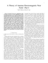
antenna has a measured reflection coefficient <strong>of</strong> -27 dB as<br />
shown in Fig. 4 <strong>and</strong> an efficiency <strong>of</strong> approximately 79% as<br />
simulated in HFSS.<br />
Phase Shifter Control Logic<br />
The control logic is used to bridge the gap between the user<br />
input (rotary switch) <strong>and</strong> the proper biasing states <strong>of</strong> the 16<br />
SPDTs. Since each switch requires two control pins, a low<br />
<strong>and</strong> a high, we needed a custom decoder <strong>and</strong> 2 hex inverters.<br />
We settled on a Gal26cv12B PLD. The control program<br />
designed for this chip uses a simple lookup table that takes the<br />
state <strong>of</strong> the 8 pins from the rotary switch <strong>and</strong> converts them to<br />
the appropriate 12 states. These 12 outputs are than run to 12<br />
inverters <strong>and</strong> one pin on each SPDT on three <strong>of</strong> the phase<br />
shifters. Each <strong>of</strong> the inverter outputs is then run the second pin<br />
on the 12 SPDTs. The DC lines run between the rotary switch<br />
the PLD, to the inverters, to the SPDTs. They are kept away<br />
from RF lines <strong>and</strong> the antennas themselves <strong>and</strong> isolated from<br />
RF path by capacitors where necessary.<br />
The PLD is available for purchase from Dataman<br />
preprogrammed for $39.27 as indicated in Table II. Many<br />
universities have PLDs on h<strong>and</strong> <strong>and</strong> the capability in house to<br />
program them. This capability could reduce or remove the<br />
cost <strong>of</strong> this component from the system. Table I lists the<br />
connections made by the PLD.<br />
Overall Design<br />
The overall layout <strong>of</strong> the RF subsystems is very important.<br />
All separate RF lines before <strong>and</strong> after the phase shifter need to<br />
be <strong>of</strong> equal length so the only phase added to the line comes<br />
from the phase shifter.<br />
We chose Wilkinson power dividers to provide power<br />
splitting because these are a simple way to split power with<br />
low reflection <strong>and</strong> even phase response.<br />
m1<br />
Frequency (G H z)<br />
m1<br />
freq= 3.300 GHz<br />
dB (s1 _1)=-2 7.0 20<br />
V alle y<br />
Fig. 4. Measured reflection coefficient in dB as a function <strong>of</strong> frequency.<br />
Note the patch is closely matched to 50 at the design frequency <strong>of</strong> 3.3 GHz.<br />
TABLE I<br />
LOGIC CONTROL LINE CONNECTIONS<br />
PLD Pin # Pin Connections<br />
Pin 1<br />
Gnd<br />
Pin 2<br />
Gnd<br />
Pin 3<br />
Gnd<br />
Pin 4<br />
Gnd<br />
Pin 5<br />
Gnd<br />
Pin 6 Rotary Switch Pin #1<br />
Pin 7<br />
Pwr (+5V)<br />
Pin 8 Rotary Switch Pin #2<br />
Pin 9 Rotary Switch Pin #3<br />
Pin 10 Rotary Switch Pin #4<br />
Pin 11 Rotary Switch Pin #5<br />
Pin 12 Rotary Switch Pin #6<br />
Pin 13 Rotary Switch Pin #7<br />
Pin 14 Rotary Switch Pin #8<br />
Pin 15 V1 <strong>of</strong> SPDT #3<br />
Pin 16 V1 <strong>of</strong> SPDT #4<br />
Pin 17 V1 <strong>of</strong> SPDT #6<br />
Pin 18 V1 <strong>of</strong> SPDT #7<br />
Pin 19 V1 <strong>of</strong> SPDT #8<br />
Pin 20 V1 <strong>of</strong> SPDT #12<br />
Pin 21<br />
Gnd<br />
Pin 22 V1 <strong>of</strong> SPDT #5<br />
Pin 23 V1 <strong>of</strong> SPDT #1<br />
Pin 24 V1 <strong>of</strong> SPDT #2<br />
Pin 25 V1 <strong>of</strong> SPDT #11<br />
Pin 26 V1 <strong>of</strong> SPDT #10<br />
Pin 27 V1 <strong>of</strong> SPDT #9<br />
Pin 28<br />
Gnd<br />
B. LED Rectenna Module<br />
The LED Rectenna array is made <strong>of</strong> 70 small 41.6mm x<br />
54.1mm tag boards displayed on a backing board. This tag is<br />
made <strong>of</strong> three main entities, a 3.3GHz single layer patch<br />
antenna, a matching network, <strong>and</strong> a voltage boosting rectifier<br />
with LED. This device takes a polarized 3.3GHz signal <strong>and</strong><br />
turns it into visual light.<br />
Single Layer Patch <strong>Antenna</strong><br />
We designed a single layer patch antenna on 1.57 mm thick<br />
Rogers RO4350B. The antenna is designed to be matched to<br />
50 ohms by adjusting the depth that the 50 ohm microstrip line<br />
penetrates it.<br />
Rectifier/LED<br />
The rectifier is a four stage charge pump that uses four<br />
Schottky diodes <strong>and</strong> four capacitors. The load is a low power<br />
LED with a low turn on voltage.<br />
We used a charge pump to provide voltage boost to the<br />
LED to increase the rectified voltage above the turn on voltage<br />
<strong>of</strong> the LED (see Fig. 5a). Adding more stages increases the<br />
DC voltage output, however losses also increase degrading<br />
performance. We balanced these effects <strong>and</strong> chose a 4 stage<br />
rectifier.<br />
Matching Network<br />
A matching network is used to provide maximum power<br />
transfer from the antenna to the rectifier with the low power<br />
LED load.<br />
To implement the matching network we utilize microstrip