FI156 Fieseler Storch - Home page di Paolo Severin
FI156 Fieseler Storch - Home page di Paolo Severin
FI156 Fieseler Storch - Home page di Paolo Severin

Create successful ePaper yourself
Turn your PDF publications into a flip-book with our unique Google optimized e-Paper software.
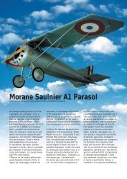
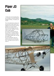
<strong>FI156</strong> <strong>Fieseler</strong> <strong>Storch</strong><br />
“…I have seen one fl ying against<br />
the wind backwards…”<br />
“…the one of Mr. such and such<br />
was coming straight down vertically,<br />
nose <strong>di</strong>ving, one meter from<br />
the ground and then landed in two<br />
meter stretch…”<br />
I had heard many stories on the<br />
<strong>Fieseler</strong> <strong>Storch</strong>, but i had never<br />
seen one, other than in world war<br />
two old movies or in books and<br />
magazines.<br />
Being a lover of the slow fl ying , of<br />
the very slow lan<strong>di</strong>ngs, I got hooked<br />
by listening to the many legends<br />
about it and became for me imperative<br />
to build one.<br />
I therefore started to get acquainted<br />
so as to have a good three<br />
views drawing, buying some from<br />
the www.bobsairdoc.com website,<br />
but among the three or four three<br />
view drawings that I received from<br />
the USA there were not two alike.<br />
I decided to stick to the most<br />
realistic one. Still on the internet on<br />
the site<br />
www.hinkleymall.com/storch.html<br />
, i purchased for $ 40 (you don’t<br />
go broke just gambling) a big book<br />
containing more than 200 copies of<br />
original drawings from the <strong>Fieseler</strong><br />
factory.<br />
Most of them were elevation views<br />
of as built details, not too useful<br />
for the project, even though interesting.<br />
However were included<br />
very precious drawings of the wing<br />
original airfoil, with the slats on the<br />
lea<strong>di</strong>ng edge, the fl aps and ailerons<br />
showing precisely the hinge points,<br />
in ad<strong>di</strong>tion to the test results in the<br />
wind tunnel.<br />
I had noticed some intriguing details<br />
of the fuselage steel structure<br />
which fascinated me. I then began<br />
to “nurture” the project.<br />
I was pondering on how to solve<br />
this or that detail, trying always to<br />
fi nd solutions that were as close as<br />
possible to the original one, but the<br />
picture that kept coming back to<br />
my mind was the steel structure of<br />
the fuselage. I started to evaluate if<br />
it was possible to build the fuselage<br />
like the one of the full scale<br />
airplane, some time before I had<br />
found small tubes in stainless steel<br />
in various <strong>di</strong>ameter size , thick only
2,5 tens of millimiter.<br />
After some calculation i was<br />
amazed: a ¼ scale fuselage over<br />
2mt. long would have weighted a<br />
little over one and half kilogram. I<br />
could not believe it. I recalculate but<br />
the result was the same. So i said<br />
“same as the full scale or nothing!”<br />
and I decided to start. One hand on<br />
my hearth and one on the wallet, I<br />
ordered over 40mt. of small tubes<br />
in <strong>di</strong>fferent sizes,worth about Euro<br />
300, to the company Castiglioni<br />
of Milano (www.castiglioni-tubi.it) .<br />
The stuff arrived right before the<br />
Christmas holidays during which I<br />
started to work.<br />
The project<br />
After scanning the 3 view drawings<br />
i began to simulate variuos scales<br />
on the computer and i decided to<br />
go with the 1/4 scale. The model<br />
that came out had a wingspan of<br />
354cm, length 242 cm and 175<br />
sq.dm of wing area.<br />
A true beast! Just for precaution,<br />
before moving on, I measured out<br />
the car and calculated that by removing<br />
the stabilizer probably was<br />
going to fi t.<br />
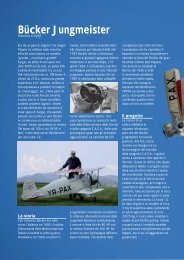
I designed the fuselage on the<br />
computer pointing out precisely<br />
the wel<strong>di</strong>ng spots of the structure ,<br />
marking them with reference to an<br />
horizontal line on the laying plan,<br />
and a vertical line to the fi rewall (fi g.<br />
1)<br />
Fig.1
By doing this i realized how functional<br />
was the original project.<br />
Basically the airplane is built using<br />
straight tubes, often parallel or perpen<strong>di</strong>cular<br />
with each other, resulting<br />
in an brilliant use of the space and<br />
the structural functionality. Whoever<br />
designed this airplane was endowed<br />
with a great rationality.<br />
I postponed the rest of the project,<br />
until after the construction of the<br />
fuselage. I was not trusting yet<br />
my calculation of the weight and,<br />
mainly, I wanted to touch with hand<br />
the strength of the structure, about<br />
which (considering the estimated<br />
lightness) I had some doubt.<br />
The fuselage<br />
Without any jig o 1/1 scale drawing<br />
to use , i started to weld the<br />
tubes with each other. It may sound<br />
strange, but the structure was<br />
very simple and , after paying lot<br />
of attention to the alignment of the<br />
fi rst wel<strong>di</strong>ngs, the work was getting<br />
easier and easier as I was ad<strong>di</strong>ng<br />
more tubes and the reference<br />
points were increasing.<br />
It’s incre<strong>di</strong>ble how fast is this way<br />
of buil<strong>di</strong>ng. As I was ad<strong>di</strong>ng the<br />
bracing tubes and the secondary<br />
spars the fuselage was getting<br />
more unwarpable and once fi nished<br />
became very robust.<br />
Basically i had no dead times, the<br />
wel<strong>di</strong>ngs (see picture above), once<br />
i got the hang of it, became easy<br />
and fast to do. I was feeling a<br />
special pleasure seeing the silver<br />
alloy fl owing through the points of<br />
junction.<br />
I fi nished the mainframe in three<br />
days of hard work: the scale tipped<br />
at 1200 grams. After having added<br />
the shock absorbing lan<strong>di</strong>ng gear,<br />
the motor mount with a tubes<br />
structure too, all the connections,<br />
the system to adjust the stabilizer<br />
incidence, the shock absorbing tail<br />
wheel,the opening door, etc., everything<br />
in steel welded, the weight<br />
went up to just 1800 grams.<br />
I used chromemolibden steel tube<br />
with <strong>di</strong>fferent <strong>di</strong>ameters to build the<br />
lan<strong>di</strong>ng gear. I had purchased these<br />
tubes years ago’ from a vendor of<br />
aeronautical materials. It’s the same<br />
material that is used to build real<br />
fuselage, such as the one of the<br />
Piper Cub.<br />
I used the same tube for the motor<br />
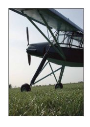
mount. The lan<strong>di</strong>ng gear works<br />
exactly like the real one and features<br />
a very long stroke, spring<br />
loaded and cushioned with cylindrical<br />
dumpers made of rubber like<br />
material at the end point. In the
end I handed the fuselage to my<br />
friend Perfetto (modeller and car<br />
body repairer), who sprayed it with<br />
a layer of primer. Looking at it with<br />
that ochre colour looked like the<br />
fuselage of a real plane.<br />
The engine cowl is made out of<br />
aluminum from lithoplate and the<br />
front is in fi berglass stratifi ed into<br />
a vac-u formed mould. I often use<br />
this method to make detailed parts<br />
in fi berglass, it’s pretty quick. After<br />
making a wooden mock-up, better<br />
also the counterweights for the<br />
static balance made out of vac-u<br />
formed PVC.<br />
I built on the ailerons working trims:<br />
I don’t know if they are benefi cial to<br />
the fl ight , but they look very good.<br />
The main spars are made of spruce.<br />
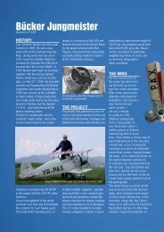
The most <strong>di</strong>ffi cult part has been<br />
buil<strong>di</strong>ng the slats. Since I wanted<br />
to match the original contour that<br />
featured extra thin trailing edges,<br />
I decided that the best way was<br />
to make a <strong>di</strong>e and make them in<br />
fi berglass. Easier said than done. I<br />
built a <strong>di</strong>e in two halves with spars<br />
and negative ribs on which I glued a<br />
1mm bent PVC sheet. (Fig. 2)<br />
After several wrong shapes resulting<br />
in weird agglomeration of<br />
fi berglass that fi lled the garbage<br />
can, i fi nally made a decent slat,<br />
but i realized that the profi le chosen<br />
was the wrong one! I had mixed up<br />
on the computer using a temporary<br />
profi le , not the fi nal one…. It<br />
happens. After the usual getting<br />
Fig. 2<br />
mad , but strong from the gained<br />
experience, i <strong>di</strong>d it all over again<br />
and fi nally i had two slats more than<br />
satisfactory. Who knows, maybe<br />
using this system you can even<br />
build wings made out of fi berglass.<br />
I put two heavy duty servos on each<br />
side of the wing, one for the fl ap<br />
and one for the aileron. The wing<br />
is hinged to the fuselage with pins,<br />
if a MDF panel is used (it does not<br />
have veins that would show ), I use<br />
it as a matrix to make a 2mm PVC<br />
vac-u formed front end piece. The<br />
vac-u forming system is the same<br />
used to make the clear canopies. I<br />
then use the PVC piece as a mould<br />
for the fi berglass. You can also<br />
mount on the airplane the PVC<br />
piece, but fi berglass is stronger and<br />
last longer.<br />
The wing<br />
Considering how light the fuselage<br />
was , I <strong>di</strong>d not care too much about<br />
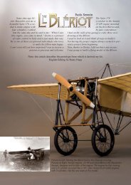
the weight of the wing. The ribs<br />
(fi g. 3) are made of 4mm lightened<br />
poplar plywood, drawn on the computer<br />
and cut with the CNC Step4<br />
(www.step-four.at) pantograph.<br />
Still with the pantograph I made the<br />
fl aps and ailerons hinges with 2mm<br />
fi breglass sheet , these included
Fig. 3<br />
and it’s kept in position with two<br />
struts made out of 10 mm <strong>di</strong>ameter<br />
aluminum tube, 1mm tick bought at<br />
the hardware store. The ends are<br />
threaded so that can be adjusted<br />
in<strong>di</strong>vidually to control the alignement<br />
of the wing. The rods tubes<br />
are covered with balsa aerodynamically<br />
shaped. In the end I covered<br />
the rods with a heatshrinkable tube<br />
(electrical type) which adhered<br />
precisely to the contour making it<br />
ready for painting. I used the same<br />
system for the struts of the lan<strong>di</strong>ng<br />
gear.<br />
The Tail surface<br />
Also in this case i used poplar<br />
plywood ribs, but unlikely the wing<br />
I used special single spars: I built a<br />
<strong>di</strong>e (Fig 4) from aluminum sections<br />
and I inserted a 10x10mm light<br />
balsa spar, soaked in an epoxy<br />
resin, covered with a carbon fi ber<br />
sox. This way you get a very strong<br />
spar, especially resistant to torsion.<br />
This system allows to make<br />
a warp resistant tail surface. As I<br />
mentioned, the tail surface incidence<br />
is adjustable on the ground by<br />
means of a screw located under the<br />
fuselage (picture on the right). The<br />
elevator is driven by a giant scale<br />
servo connected to a stiff carbon<br />
pushrod which drives a steel levers<br />
mechanism; the rudder is driven by<br />
a giant scale servo and a pull-pull<br />
cable system.<br />
Fig. 4<br />
Covering<br />
The entire model is covered with<br />
Solartex green olive colour, I have<br />
chosen this colour so I was already<br />
getting the interior of the right colour.<br />
I went with the typical method<br />
for the wing, while for the fuselage<br />
I tacked the fabric with the heat<br />
sealing iron and, after laying a CA<br />
string on the tubes, I wrapped the<br />
fabric around, going over with the<br />
iron and I achieved a fl awless gluing.<br />
I <strong>di</strong>d not encounter any problem<br />
also because the fuselage of the<br />
<strong>Storch</strong> is square and very simple.<br />
While I was covering the fuselage<br />
it came to my mind the fuselage of<br />
a Piper Cub that I had seen being<br />
restored at an aircraft repair shop…<br />
<strong>di</strong>mensions aside it was identical.<br />
I had more and more the feeling of<br />
working on a real plane. The canopy<br />
is made of 1mm PVC screwed to<br />
little plates welded to the fuselage<br />
and the frames are made of aluminum<br />
attached with 1,5mm rivets. It<br />
makes a great impression. I painted<br />
the airplane with nitro colours paint,<br />
inclu<strong>di</strong>ng symbols and writings. At<br />
the end I sprayed a layer of matt<br />
clear cote, but fi rst I aged the plane<br />
rubbing it with extra fi ne grain sandpaper<br />
to wear off the paint in the<br />
points of major wear.
The Engine<br />
After I have been looking for an<br />
Enya 240 V, 4 stroke V twin engine,<br />
in vain , it’s not produced for the<br />
moment, I purchased on the internet<br />
(www.laserengines.com) a Laser<br />
300 engine, 90° twin , 4stroke,<br />
50cc.<br />
The Laser engines are used by<br />
many scale modelers among which<br />
we fi nd the world champions Max<br />
Merchenschlager, Pete McDermott<br />
and Mick Reeves.<br />
The Laser 300 seems to be designed<br />
right for this model: it fi ts<br />
perfectly within the cowl and,<br />
looking from the air intake opening,<br />
resembles the Argus A10 that was<br />
used on the full scale airplane.<br />
I mounted it on the motor mount<br />
structure making some vibrations<br />
dumpers of rubber compound; I<br />
also installed an on board battery<br />
for the glow plugs. The battery gets<br />
activated by the throttle pushrod<br />
when the engine is on idle (picture<br />
above). I used some stainless steel<br />
corrugated gas pipe, bought at<br />
the hardware store, to connect the<br />
exhausts to the engine heads.<br />
After some adjustments, the overall<br />
package was very reliable and the<br />
sound , especially at the low end, is<br />
fascinating.<br />
The fi nished model wheighs 11,5<br />
kilos, the wing load is just 65 gr/<br />
sq.dm.: I could have had my dog<br />
Pino fl y in it, but I could not convince<br />
him.<br />
Jokes aside, i think this is the<br />
best way of buil<strong>di</strong>ng and the most<br />
satisfactory that i have ever used<br />
in more than thirty years. Of course<br />
the cost of the material (tubes, silver<br />
wel<strong>di</strong>ng etc.) is substantial, but<br />
I think that if I had built a model of<br />
this size using conventional materials<br />
it would not have been much<br />
cheaper.
Many beautiful airplanes have the fuselage<br />
made with a steel structure<br />
and can be built using this method,<br />
therefore I believe that soon I will<br />
have back the wel<strong>di</strong>ng pipe in my<br />
hand.<br />
The maiden fl ight unfolded as per<br />
usual routine: shaking knees, loose<br />
stomack, imminent heart attack…<br />
luckily Michele (great thumb) was on<br />
the fi eld and so,since I was having a<br />
panick attack, I handed the transmitter<br />
to him to land the model that<br />
was fl ying great. After that I started<br />
to have fun. The model looks good,<br />
the fl ight is hundred times better.<br />
It takes off in three, four meters,<br />
goes up like if it’s on a ramp, nose<br />
<strong>di</strong>ving with the fl aps down is very<br />
slow, it’s <strong>di</strong>ffi cult to believe it’s not<br />
hanging on to a rope.<br />
It’s very controllable at any speed,<br />
even when it looks almost stand still<br />
reacts to all the controls, to make<br />
it stall you have to really commit<br />
yourself.<br />
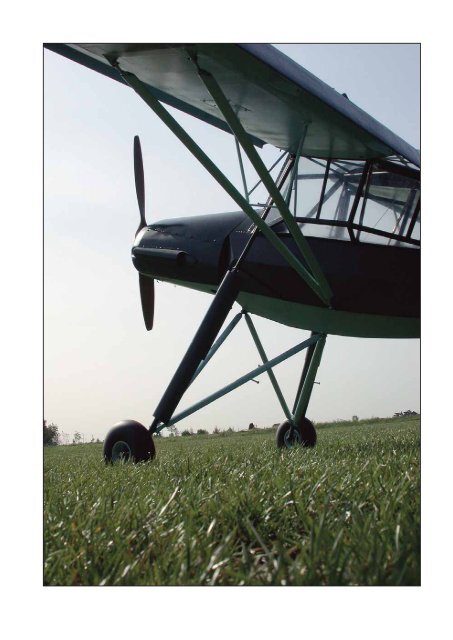
Needless to say that with such<br />
qualities lan<strong>di</strong>ngs are a breeze,<br />
especially when you see the long<br />
sweet stroke of the shock absorbers<br />
on the very tall lan<strong>di</strong>ng gear<br />
that makes the plane look like a big<br />
stork…. maybe not all those that I<br />
heard were stories.<br />
www.paoloseverin.it