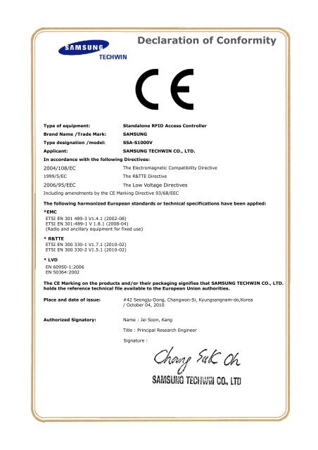
Declaration of Conformity…. - Samsung CCTV
Declaration of Conformity…. - Samsung CCTV
Declaration of Conformity…. - Samsung CCTV

Create successful ePaper yourself
Turn your PDF publications into a flip-book with our unique Google optimized e-Paper software.
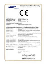
<strong>Declaration</strong> <strong>of</strong> <strong>Conformity…</strong>.<br />
Type <strong>of</strong> equipment:<br />
Brand Name /Trade Mark:<br />
Type designation /model:<br />
Applicant:<br />
Standalone RFID Access Controller<br />
SAMSUNG<br />
SSA-S1000V<br />
SAMSUNG TECHWIN CO., LTD.<br />
In accordance with the following Directives:<br />
2004/108/EC<br />
1999/5/EC<br />
2006/95/EEC<br />
The Electromagnetic Compatibility Directive<br />
The R&TTE Directive<br />
The Low Voltage Directives<br />
Including amendments by the CE Marking Directive 93/68/EEC<br />
The following harmonized European standards or technical specifications have been applied:<br />
*EMC<br />
ETSI EN 301 489-3 V1.4.1 (2002-08)<br />
ETSI EN 301-489-1 V 1.8.1 (2008-04)<br />
(Radio and ancillary equipment for fixed use)<br />
* R&TTE<br />
ETSI EN 300 330-1 V1.7.1 (2010-02)<br />
ETSI EN 300 330-2 V1.5.1 (2010-02)<br />
* LVD<br />
EN 60950-1:2006<br />
EN 50364:2002<br />
The CE Marking on the products and/or their packaging signifies that SAMSUNG TECHWIN CO., LTD.<br />
holds the reference technical file available to the European Union authorities.<br />
Place and date <strong>of</strong> issue:<br />
#42 Seongju-Dong, Changwon-Si, Kyungsangnam-do,Korea<br />
/ October 04, 2010<br />
Authorized Signatory:<br />
Name : Jei Soon, Kang<br />
Title : Principal Research Engineer<br />
Signature :
Report No.: EMC-CE-2291<br />
Page : 2 <strong>of</strong> 39<br />
http://www.emc2000.co.kr<br />
Contents<br />
1. Applicant information .................................................................................................................................... 3<br />
2. Laboratory information ................................................................................................................................. 4<br />
3. Test system configuration............................................................................................................................... 5<br />
3.1 Operation environment ..................................................................................................................... 5<br />
3.2 Measurement Uncertainty................................................................................................................. 5<br />
4. Description <strong>of</strong> E.U.T. ...................................................................................................................................... 6<br />
4.1 General information.......................................................................................................................... 6<br />
4.2 Product description ........................................................................................................................... 7<br />
4.3 Auxiliary equipments........................................................................................................................ 8<br />
4.4 Test configuration ............................................................................................................................ 8<br />
4.5 Operating conditions......................................................................................................................... 9<br />
5. Summary <strong>of</strong> test results................................................................................................................................ 10<br />
5.1 Modification to the E.U.T. .............................................................................................................. 10<br />
5.2 Summary <strong>of</strong> EMI emission test results ........................................................................................... 10<br />
5.3 Performance criteria........................................................................................................................ 12<br />
6. Test results ..................................................................................................................................................... 20<br />
6.1 Radiated Emission .......................................................................................................................... 20<br />
6.2 Electrostatic Discharge ................................................................................................................... 24<br />
6.3 Radio Frequency Electromagnetic Fields ....................................................................................... 27<br />
6.4 Electric Fast Transient/BURST....................................................................................................... 30<br />
6.5 Conducted Immunity ...................................................................................................................... 32<br />
7. E.U.T. photographs....................................................................................................................................... 34<br />
EMC Compliance Ltd. 480-5 Sin-dong, Yeongtong-gu, Suwon-city, Gyeonggi-do, 443-390, Korea<br />
TEL: 82 31 336 9919 FAX: 82 31 336 4767<br />
This test report shall not be reproduced, except in full, without the written approval.
Report No.: EMC-CE-2291<br />
Page : 3 <strong>of</strong> 39<br />
http://www.emc2000.co.kr<br />
1. Applicant information<br />
Applicant:<br />
SAMSUNG TECHWIN CO., LTD.<br />
Address:<br />
#42 Seongju-Dong, Changwon-si,<br />
Kyungsangnam-do, Korea<br />
Telephone: +82-70-7147-8376<br />
Fax: +82-31-8018-3717<br />
E-mail:<br />
js2002.kang@samsung.com<br />
Contact name: Kang Jei Soon<br />
Manufacturer:<br />
Address:<br />
IDTECH Co., Ltd.<br />
5F, Ace Techno Tower B/D, 684-1 Deungchon-Dong,<br />
Gangseo-Gu, Seoul 157-030, Korea<br />
EMC Compliance Ltd. 480-5 Sin-dong, Yeongtong-gu, Suwon-city, Gyeonggi-do, 443-390, Korea<br />
TEL: 82 31 336 9919 FAX: 82 31 336 4767<br />
This test report shall not be reproduced, except in full, without the written approval.
Report No.: EMC-CE-2291<br />
Page : 4 <strong>of</strong> 39<br />
http://www.emc2000.co.kr<br />
2. Laboratory information<br />
Address<br />
EMC compliance Ltd.<br />
480-5 Sin-dong, Yeongtong-gu, Suwon-city, Gyeonggi-do, 443-390, Korea<br />
Telephone Number: 82 31 336 9919<br />
Facsimile Number: 82 31 336 4767<br />
FCC CAB.: KR0040<br />
VCCI Registration No.: R-3327, G-198, C-3706, T-1849<br />
Industry Canada Registration No. : 8035A<br />
KOLAS NO.: 231<br />
SITE MAP<br />
Suwon city<br />
EMC compliance<br />
EMC Compliance Ltd. 480-5 Sin-dong, Yeongtong-gu, Suwon-city, Gyeonggi-do, 443-390, Korea<br />
TEL: 82 31 336 9919 FAX: 82 31 336 4767<br />
This test report shall not be reproduced, except in full, without the written approval.
Report No.: EMC-CE-2291<br />
Page : 5 <strong>of</strong> 39<br />
http://www.emc2000.co.kr<br />
3. Test system configuration<br />
3.1 Operation environment<br />
Temperature Humidity Pressure<br />
Chamber(10 m) : 26 °C 53 % R.H. -<br />
Shielded room(ESD) : 29 °C 43 % R.H. 100.6 kPa<br />
Test site<br />
These testing items were performed following locations;<br />
Shielded Room<br />
Chamber (10 m)<br />
Fully anechoic chamber (3 m)<br />
: ESD, EFT/Burst, CS<br />
: Radiated Emission<br />
: RS<br />
3.2 Measurement Uncertainty<br />
All measurements involve certain levels <strong>of</strong> uncertainties, especially in field <strong>of</strong> EMC.<br />
The factors contributing to uncertainties are test receiver, cable loss, antenna factor<br />
calibration, Antenna directivity, antenna factor variation with height, antenna phase center<br />
variation, antenna frequency interpolation, measurement distance variation, site imperfection,<br />
mismatch, and system repeatability. Based on CISPR 16-4-2, the measurement uncertainty<br />
level with a 95 % confidence level was applied.<br />
Radiated Emission measurement :( k = 2, 95 %)<br />
30 MHz ~ 300 MHz: 3 m: ± 4.3 [dB]<br />
10 m: ± 4.3 [dB]<br />
300 MHz ~ 1 000 MHz: 3 m: ± 4.4 [dB]<br />
10 m: ± 4.3 [dB]<br />
Radio Frequency Electromagnetic Fields :( k = 2, 95 %)<br />
± 1.09 [dB]<br />
EMC Compliance Ltd. 480-5 Sin-dong, Yeongtong-gu, Suwon-city, Gyeonggi-do, 443-390, Korea<br />
TEL: 82 31 336 9919 FAX: 82 31 336 4767<br />
This test report shall not be reproduced, except in full, without the written approval.
Report No.: EMC-CE-2291<br />
Page : 6 <strong>of</strong> 39<br />
http://www.emc2000.co.kr<br />
4. Description <strong>of</strong> E.U.T.<br />
4.1 General information<br />
EMC Compliance Ltd. 480-5 Sin-dong, Yeongtong-gu, Suwon-city, Gyeonggi-do, 443-390, Korea<br />
TEL: 82 31 336 9919 FAX: 82 31 336 4767<br />
This test report shall not be reproduced, except in full, without the written approval.
Report No.: EMC-CE-2291<br />
Page : 7 <strong>of</strong> 39<br />
http://www.emc2000.co.kr<br />
4.2 Product description<br />
Type <strong>of</strong> product<br />
Standalone RFID Access Controller<br />
Model name (Basic) SSA-S1000V<br />
Model name (Variant) N/A<br />
Difference -<br />
Serial no<br />
Engineering Sample<br />
Trade name -<br />
Testing voltage<br />
Product rating<br />
Internal Clock Frequency<br />
Frequency<br />
Type <strong>of</strong> Modulation<br />
Number <strong>of</strong> Channels<br />
Type <strong>of</strong> Antenna<br />
Power supply<br />
DC 12 V<br />
DC 12 V<br />
16 MHz<br />
125 kHz<br />
PSK<br />
1 channel<br />
Integral (Loop coil antenna)<br />
DC 12 V / Max.120mA<br />
Extreme Power supply Lower voltage: DC 10.2 V, Upper voltage: DC 13.8V<br />
Operating Temperature -20 ℃ ~ 55 ℃*<br />
Operating Humidity<br />
Dimension<br />
Weight<br />
Reading Time(card)<br />
Input port<br />
Output port<br />
LED indicator<br />
Beeper<br />
10% to 90% relative humidity non-condensing<br />
47*122*26 (W*H*D)<br />
130g<br />
30ms<br />
2ea (External LED control , External buzzer control)<br />
26bit Wiegand<br />
2 Color LED Indicators (Red and Green)<br />
Piezo buzzer<br />
Note -<br />
EMC Compliance Ltd. 480-5 Sin-dong, Yeongtong-gu, Suwon-city, Gyeonggi-do, 443-390, Korea<br />
TEL: 82 31 336 9919 FAX: 82 31 336 4767<br />
This test report shall not be reproduced, except in full, without the written approval.
Report No.: EMC-CE-2291<br />
Page : 8 <strong>of</strong> 39<br />
http://www.emc2000.co.kr<br />
4.3 Auxiliary equipments<br />
Type Model / Part # Serial number Manufacturer<br />
DC Power Supply PS2520G TW50517 TEKTONIX<br />
Door Lock IEM-280 229562 -<br />
Magnetic 832T - Amseco<br />
Switch D16LMU3 - DECA<br />
4.4 Test configuration<br />
EMC Compliance Ltd. 480-5 Sin-dong, Yeongtong-gu, Suwon-city, Gyeonggi-do, 443-390, Korea<br />
TEL: 82 31 336 9919 FAX: 82 31 336 4767<br />
This test report shall not be reproduced, except in full, without the written approval.
Report No.: EMC-CE-2291<br />
Page : 9 <strong>of</strong> 39<br />
http://www.emc2000.co.kr<br />
Note<br />
Start End Cable<br />
*<br />
Name I/O port Name I/O port Length(m) Spec.<br />
DC Power<br />
1<br />
Power<br />
Power 1.5 Non-Shield<br />
Supply<br />
2 EUT NC Door Lock NC 1.0 Non-Shield<br />
(Standalone<br />
3 RFID Door Sensor Magnetic Door Sensor 1.0 Non-Shield<br />
4 Access EXIT Switch EXIT 1.0 Non-Shield<br />
5<br />
Controller)<br />
Chime Bell Open - 1.0 Non-Shield<br />
6 TTL Out Open - 1.0 Non-Shield<br />
7<br />
COM Ground<br />
COM Ground<br />
Door Lock<br />
(COM-)<br />
(COM-)<br />
1.0 Non-Shield<br />
8<br />
DC Power COM Ground<br />
COM Ground<br />
Magnetic<br />
Supply (COM-)<br />
(COM-)<br />
1.0 Non-Shield<br />
9<br />
COM Ground<br />
COM Ground<br />
Switch<br />
(COM-)<br />
(COM-)<br />
1.0 Non-Shield<br />
4.5 Operating conditions<br />
The EUT was configured as normal intended use.<br />
Test mode<br />
1<br />
RF Card Recognition Mode<br />
Door Lock, Exit Button Check Mode<br />
Normal operating<br />
EMC Compliance Ltd. 480-5 Sin-dong, Yeongtong-gu, Suwon-city, Gyeonggi-do, 443-390, Korea<br />
TEL: 82 31 336 9919 FAX: 82 31 336 4767<br />
This test report shall not be reproduced, except in full, without the written approval.
Report No.: EMC-CE-2291<br />
Page : 10 <strong>of</strong> 39<br />
http://www.emc2000.co.kr<br />
5. Summary <strong>of</strong> test results<br />
5.1 Modification to the E.U.T.<br />
- None<br />
5.2 Summary <strong>of</strong> EMI emission test results<br />
- The following standards have been applied:<br />
ETSI EN 301-489-3 V 1.4.1 (2002-08)<br />
Electromagnetic compatibility and Radio spectrum Matters (ERM); Electro Magnetic Compatibility<br />
(EMC) standard for equipment and services; Part 3: Specific conditions for Short Range Device<br />
(SRD) operating on frequency between 9 kHz and 40 GHz<br />
ETSI EN 301-489-1 V 1.8.1 (2008-04)<br />
Electromagnetic compatibility and Radio spectrum Matters (ERM); ElectroMagnetic Compatibility<br />
(EMC) standard for radio equipment and services; Part 1: Common technical requirements<br />
Test items Result<br />
Basic Standard Description Test Result<br />
ETSI EN 301 489-3 V1.4.1:2002<br />
Electromagnetic compatibility and Radio<br />
spectrum Matters(ERM); Electro Magnetic<br />
Compatibility (EMC) standard for equipment and<br />
services; Part 3: Specific conditions for Short<br />
Range Device (SRD) operating on frequency<br />
Between 9 kHz and 40 GHz<br />
Pass<br />
Fail<br />
ETSI EN 301 489-1 clause 8.2<br />
Radiated emission-enclosure <strong>of</strong> ancillary<br />
equipment<br />
Pass<br />
Fail<br />
ETSI EN 301 489-1 clause 8.3 Conducted emission-DC power input/output port N/A(*)<br />
ETSI EN 301 489-1 clause 8.4 Conducted emission-AC mains input/output port N/A<br />
ETSI EN 301 489-1 clause 8.5 Harmonic current emission-AC mains input port N/A<br />
EMC Compliance Ltd. 480-5 Sin-dong, Yeongtong-gu, Suwon-city, Gyeonggi-do, 443-390, Korea<br />
TEL: 82 31 336 9919 FAX: 82 31 336 4767<br />
This test report shall not be reproduced, except in full, without the written approval.
Report No.: EMC-CE-2291<br />
Page : 11 <strong>of</strong> 39<br />
http://www.emc2000.co.kr<br />
ETSI EN 301 489-1 clause 8.6<br />
Voltage fluctuations and flicker-<br />
AC mains input port<br />
N/A<br />
ETSI EN 301 489-1 clause 8.7 Conducted emission-Telecommunication port N/A<br />
ETSI EN 301 489-1 clause 9.2<br />
RF electromagnetic field (80 MHz ~ 1 GHz<br />
and 1.4 GHz ~ 2.7 GHz)-Enclosure<br />
Pass<br />
Fail<br />
ETSI EN 301 489-1 clause 9.3 Electrostatic discharge-Enclosure Pass Fail<br />
ETSI EN 301-489-1 clause 9.4<br />
Fast transient common mode- Signal,<br />
Telecommunication and control ports,<br />
DC and AC power port<br />
Pass<br />
Fail<br />
ETSI EN 301-489-1 clause 9.5<br />
RF common mode 0.15 MHz to 80 MHz-<br />
Signal, Telecommunication and control<br />
ports, DC and AC power ports<br />
Pass<br />
Fail<br />
ETSI EN 301-489-1 clause 9.6 Transients and surges-DC power input ports N/A<br />
ETSI EN 301-489-1 clause 9.7<br />
ETSI EN 301-489-1 clause 9.8<br />
Voltage dips and interruptions-AC mains power<br />
input ports<br />
Surges, line to line and line to ground-AC mains<br />
power input ports, Telecommunication port<br />
N/A<br />
N/A<br />
* Power cable is shorter than 3 meter, so conducted Emission test was skipped.<br />
EMC Compliance Ltd. 480-5 Sin-dong, Yeongtong-gu, Suwon-city, Gyeonggi-do, 443-390, Korea<br />
TEL: 82 31 336 9919 FAX: 82 31 336 4767<br />
This test report shall not be reproduced, except in full, without the written approval.
Report No.: EMC-CE-2291<br />
Page : 12 <strong>of</strong> 39<br />
http://www.emc2000.co.kr<br />
5.3 Performance criteria<br />
ETSI EN 301-489-1 V 1.8.1 (2008-04)<br />
The performance criteria are used to take a decision on whether a radio equipment passes or fails<br />
immunity tests. For the purpose <strong>of</strong> the present document four categories <strong>of</strong> performance criteria apply:<br />
•Performance criteria for continuous phenomena applied to transmitters;<br />
•Performance criteria for transient phenomena applied to transmitters;<br />
•Performance criteria for continuous phenomena applied to receivers;<br />
•Performance criteria for transient phenomena applied to receivers;<br />
Normally, the performance criteria depend on the type <strong>of</strong> radio equipment. Thus, the present document<br />
only contains general performance criteria commonly used for the assessment <strong>of</strong> radio equipment. More<br />
specific and product-related performance criteria for a dedicated type <strong>of</strong> radio equipment may be found<br />
in the part <strong>of</strong> EN 301 489 series [11] dealing with the particular type <strong>of</strong> radio equipment.<br />
EMC Compliance Ltd. 480-5 Sin-dong, Yeongtong-gu, Suwon-city, Gyeonggi-do, 443-390, Korea<br />
TEL: 82 31 336 9919 FAX: 82 31 336 4767<br />
This test report shall not be reproduced, except in full, without the written approval.
Report No.: EMC-CE-2291<br />
Page : 13 <strong>of</strong> 39<br />
http://www.emc2000.co.kr<br />
* Performance criteria for continuous phenomena applied to transmitters and receivers<br />
If no further details are given in the relevant part <strong>of</strong> EN 301 489 series [11] dealing with the<br />
Particular type <strong>of</strong> radio equipment, the following general performance criteria for continuous<br />
Phenomena shall apply.<br />
During and after the test, the apparatus shall continue to operate as intended. No degradation <strong>of</strong><br />
Performance or loss <strong>of</strong> function is allowed below a permissible performance level specified by the<br />
Manufacturer when the apparatus is used as intended. In some cases this permissible performance<br />
level may be replaced by a permissible loss <strong>of</strong> performance.<br />
During the test the EUT shall not unintentionally transmit or change its actual operating state and<br />
stored data.<br />
If the minimum performance level or the permissible performance loss is not specified by the<br />
Manufacturer, then either <strong>of</strong> these may be deduced from the product description and Documentation and<br />
what the user may reasonably expect from the apparatus if used as Intended.<br />
EMC Compliance Ltd. 480-5 Sin-dong, Yeongtong-gu, Suwon-city, Gyeonggi-do, 443-390, Korea<br />
TEL: 82 31 336 9919 FAX: 82 31 336 4767<br />
This test report shall not be reproduced, except in full, without the written approval.
Report No.: EMC-CE-2291<br />
Page : 14 <strong>of</strong> 39<br />
http://www.emc2000.co.kr<br />
* Performance criteria for transient phenomena applied to Transmitters and receivers<br />
If no further details are given in the relevant part <strong>of</strong> EN 301 489 series [11] dealing with the<br />
Particular type <strong>of</strong> radio equipment, the following general performance criteria for transient<br />
Phenomena shall apply.<br />
After the test, the apparatus shall continue to operate as intended. No degradation <strong>of</strong> performance or<br />
Loss <strong>of</strong> function is allowed below a permissible Performance level specified by the manufacturer,<br />
When the apparatus is used as intended. In Some cases this permissible performance level may be<br />
replaced by a permissible loss <strong>of</strong> performance.<br />
During the EMC exposure to an electromagnetic phenomenon, a degradation <strong>of</strong> performance is,<br />
However, allowed. No change <strong>of</strong> the actual mode <strong>of</strong> operation (e.g. unintended transmission) or stored<br />
Data is allowed.<br />
If the minimum performance level or the permissible performance loss is not specified by the<br />
manufacturer, then either <strong>of</strong> these may be deduced from the product description and documentation and<br />
what the user may reasonably expect from the apparatus if used as intended.<br />
EMC Compliance Ltd. 480-5 Sin-dong, Yeongtong-gu, Suwon-city, Gyeonggi-do, 443-390, Korea<br />
TEL: 82 31 336 9919 FAX: 82 31 336 4767<br />
This test report shall not be reproduced, except in full, without the written approval.
Report No.: EMC-CE-2291<br />
Page : 15 <strong>of</strong> 39<br />
http://www.emc2000.co.kr<br />
* Performance criteria for equipment which does not provide a continuous communication link<br />
For radio equipment which does not provide a continuous communication link, the performance<br />
criteria described in clauses 6.1 and 6.2 are not appropriate, then the manufacturer shall declare,<br />
for inclusion in the test report, his own specification for an acceptable level <strong>of</strong> performance<br />
or degradation <strong>of</strong> performance during and/or after the immunity tests. The performance specification<br />
shall be included in the product description and documentation. The related specifications set out in<br />
clause 5.3 have also to be taken into account.<br />
The performance criteria specified by the manufacturer shall give the same degree <strong>of</strong> immunity<br />
protection as called for in clauses 6.1 and 6.2.<br />
* Performance criteria for ancillary equipment tested on a stand alone basis<br />
If ancillary equipment is intended to be tested on a stand alone basis, the performance criteria<br />
described in clauses 6.1 and 6.2 are not appropriate, then the manufacturer shall declare,<br />
for inclusion in the test report, his own specification for an acceptable level <strong>of</strong> performance or<br />
degradation <strong>of</strong> performance during and/or after the immunity tests.<br />
The performance specification shall be included in the product description and documentation.<br />
The related specifications set out in clause 5.3 have also to be taken into account.<br />
The performance criteria specified by the manufacturer shall give the same degree <strong>of</strong> immunity<br />
protection as called for in clauses 6.1 and 6.2.<br />
EMC Compliance Ltd. 480-5 Sin-dong, Yeongtong-gu, Suwon-city, Gyeonggi-do, 443-390, Korea<br />
TEL: 82 31 336 9919 FAX: 82 31 336 4767<br />
This test report shall not be reproduced, except in full, without the written approval.
Report No.: EMC-CE-2291<br />
Page : 16 <strong>of</strong> 39<br />
http://www.emc2000.co.kr<br />
ETSI EN 301-489-3 V 1.4.1 (2002-08)<br />
* Classification <strong>of</strong> SRD equipment<br />
The product family <strong>of</strong> Short Range Device is divided into three classes <strong>of</strong> equipment, each having its<br />
own set <strong>of</strong> minimum performance criteria. This classification is based upon impact on persons and/or<br />
good in case the equipment does not operate above the specified minimum performance level under<br />
EMC stress.<br />
Class Of SRD<br />
equipment<br />
1<br />
2<br />
3<br />
Table 3<br />
During test<br />
Highly reliable SRD communication media; e.g serving human life<br />
inherent systems (may result in physical risk to a person)<br />
Medium reliable SRD communication media; e.g causing inconvenience to<br />
persons, which cannot simply be overcome by other means<br />
Standard reliable SRD communication media; e.g inconvenience to persons,<br />
which can simply be overcome by other means (e.g. manual)<br />
A non-exhaustive list <strong>of</strong> SRD equipment and its classification is given in annex B<br />
* General performance criteria<br />
The performance criteria for the different classes <strong>of</strong> SRD equipment (see table 3) in combination with the<br />
different equipment types (see table 1) during and after immunity test are specified in this clause;<br />
•Performance criteria A for immunity test with phenomena <strong>of</strong> a continuous nature;<br />
•Performance criteria B for immunity test with phenomena <strong>of</strong> a transient nature;<br />
•Performance criteria for immunity tests power interruption exceeding a certain time are specified in<br />
clause 7.2.2, table 6<br />
EMC Compliance Ltd. 480-5 Sin-dong, Yeongtong-gu, Suwon-city, Gyeonggi-do, 443-390, Korea<br />
TEL: 82 31 336 9919 FAX: 82 31 336 4767<br />
This test report shall not be reproduced, except in full, without the written approval.
Report No.: EMC-CE-2291<br />
Page : 17 <strong>of</strong> 39<br />
http://www.emc2000.co.kr<br />
* Performance table<br />
Table 4<br />
Class 1 SRD equipment<br />
Criteria During test After test<br />
A<br />
B<br />
Operate as intended no loss<br />
Function for equipment type Ⅱ<br />
The minimum performance<br />
Shall be 12 dB SINAD no<br />
unintentional responses<br />
May be loss <strong>of</strong> function<br />
(one or more) no unintentional<br />
responses<br />
Class 2 SRD equipment<br />
Operate as intended for equipment type Ⅱ<br />
The communication link shall be maintained<br />
No loss <strong>of</strong> function no degradation <strong>of</strong><br />
performance on loss <strong>of</strong> stored data or user<br />
programmable functions<br />
Operate as intended lost function(s)<br />
Shall be self-recoverable no degradation or<br />
performance no loss <strong>of</strong> stored data or user<br />
programmable functions<br />
Criteria During test After test<br />
A<br />
B<br />
Operate as intended no loss<br />
Function for equipment type Ⅱ<br />
The minimum performance<br />
Shall be 6 dB SINAD no<br />
unintentional responses<br />
May be loss <strong>of</strong> function<br />
(one or more) no unintentional<br />
responses<br />
Class 3 SRD equipment<br />
Operate as intended for equipment type Ⅱ<br />
The communication link shall be maintained<br />
No loss <strong>of</strong> function no degradation <strong>of</strong><br />
performance on loss <strong>of</strong> stored data or user<br />
programmable functions<br />
Operate as intended lost function(s)<br />
Shall be self-recoverable no degradation or<br />
performance no loss <strong>of</strong> stored data or user<br />
programmable functions<br />
Criteria During test After test<br />
A and B<br />
May be loss <strong>of</strong> function<br />
(one or more) no unintentional<br />
responses<br />
Operate as intended, for equipment type Ⅱ The<br />
communication link may be lost, but shall be<br />
recoverable by user no degradation <strong>of</strong><br />
performance lost functions shall be selfrecoverable<br />
EMC Compliance Ltd. 480-5 Sin-dong, Yeongtong-gu, Suwon-city, Gyeonggi-do, 443-390, Korea<br />
TEL: 82 31 336 9919 FAX: 82 31 336 4767<br />
This test report shall not be reproduced, except in full, without the written approval.
Report No.: EMC-CE-2291<br />
Page : 18 <strong>of</strong> 39<br />
http://www.emc2000.co.kr<br />
* Performance criteria for Continuous phenomena applied to Transmitters (CT)<br />
For equipment <strong>of</strong> type ⅠorⅡ including ancillary equipment tested on a stand alone basis,<br />
The performance criteria A <strong>of</strong> the applicable class as given in clause 6.3 shall apply.<br />
For equipment <strong>of</strong> type Ⅱor type Ⅲ requires a communication link that is maintained during the test,<br />
it shall be verified be appropriated means supplied by the manufacturer that the communication link<br />
is maintained during each individual exposure in the test sequence.<br />
Where the EUT is a transmitter, tests shall be repeated with the EUT in standby mode to ensure<br />
that any unintentional transmission does occur.<br />
* Performance criteria for Transient phenomena applied to Transmitters (TT)<br />
For equipment <strong>of</strong> type ⅠorⅡ, including ancillary equipment tested on a stand alone basis,<br />
The performance criteria B <strong>of</strong> the applicable class as given in clause 6.3 shall apply,<br />
except for power interruptions exceeding a certain time the performance criteria deviations<br />
are specified in clause 7.2.2.<br />
For equipment <strong>of</strong> type Ⅱor type Ⅲ requires a communication link that is maintained during the test,<br />
it shall be verified be appropriated means supplied by the manufacturer during each individual exposure<br />
in the test sequence.<br />
Where the EUT is a transmitter, test shall be repeated with the EUT in standby mode to ensure that any<br />
unintentional transmission does not occur.<br />
* Performance criteria for Continuous phenomena applied to Receivers (CR)<br />
For equipment <strong>of</strong> type ⅠorⅡ including ancillary equipment tested on a stand alone basis,<br />
The performance criteria A <strong>of</strong> the applicable class as given in clause 6.3 shall apply.<br />
For equipment <strong>of</strong> type Ⅱor type Ⅲ requires a communication link that is maintained during the test,<br />
it shall be verified be appropriated means supplied by the manufacturer that the communication link<br />
is maintained during each individual exposure in the test sequence.<br />
Where the EUT is a transceiver, under no circumstances shall the transmitter operate unintentionally<br />
during the test.<br />
EMC Compliance Ltd. 480-5 Sin-dong, Yeongtong-gu, Suwon-city, Gyeonggi-do, 443-390, Korea<br />
TEL: 82 31 336 9919 FAX: 82 31 336 4767<br />
This test report shall not be reproduced, except in full, without the written approval.
Report No.: EMC-CE-2291<br />
Page : 19 <strong>of</strong> 39<br />
http://www.emc2000.co.kr<br />
* Performance criteria for Transient phenomena applied to Receivers (TR)<br />
For equipment <strong>of</strong> type ⅠorⅡ, including ancillary equipment tested on a stand alone basis,<br />
The performance criteria B <strong>of</strong> the applicable class as given in clause 6.3 shall apply,<br />
except for power interruptions exceeding a certain time the performance criteria deviations are<br />
specified in clause 7.2.2.<br />
For equipment <strong>of</strong> type Ⅱor type Ⅲ requires a communication link that is maintained during the test,<br />
this shall be verified by appropriate means supplied by the manufacturer during each individual<br />
exposure in the test sequence.<br />
Where the EUT is a transceiver, under no circumstances shall the transmitter operate unintentionally<br />
during the test.<br />
* Performance criteria for ancillary equipment tested on a stand alone basis<br />
The provision <strong>of</strong> EN 301 489-1 [1], clause 6.4, shall apply.<br />
EMC Compliance Ltd. 480-5 Sin-dong, Yeongtong-gu, Suwon-city, Gyeonggi-do, 443-390, Korea<br />
TEL: 82 31 336 9919 FAX: 82 31 336 4767<br />
This test report shall not be reproduced, except in full, without the written approval.
Report No.: EMC-CE-2291<br />
Page : 20 <strong>of</strong> 39<br />
http://www.emc2000.co.kr<br />
6. Test results<br />
6.1 Radiated Emission<br />
Test specification ETSI EN 301 489-1 clause 8.2<br />
Test mode<br />
Operating mode<br />
Date 2010. 08. 18<br />
Testing voltage<br />
Test facility<br />
DC 12 V<br />
10 m Chamber<br />
Temperature (°C) 26 °C Humidity (% R.H.) 53 % R.H.<br />
Remarks<br />
Complied<br />
Minimum limit margin is 7.4 dB at 32.034 MHz.<br />
Minimum limit margin is 7.4 dB at 224.003 MHz.<br />
6.1.1 Limits <strong>of</strong> radiated emission measurement<br />
Frequency<br />
Limit (Quasi-peak)<br />
30 MHz ~ 230 MHz 30 dB(μV/m)<br />
230 MHz ~ 100 0 MHz 37 dB(μV/m)<br />
6.1.2 Measurement procedure<br />
The test was done at a 10 m chamber with a quasi-peak detector. EUT was placed on EUT was placed<br />
on a non-metallic table height <strong>of</strong> 0.8 m above the reference ground plane. Cables were folded back<br />
and forth forming a bundle 0.3 m to 0.4 m long and were hanged at a 0.4 m height to the ground<br />
plane. Cables connected to EUT were fixed to cause maximum emission. Test was made with the<br />
antenna positioned in both the horizontal and vertical planes <strong>of</strong> polarization. The measurement antenna<br />
was varied in height above the conducting ground plane to obtain the maximum signal strength.<br />
EMC Compliance Ltd. 480-5 Sin-dong, Yeongtong-gu, Suwon-city, Gyeonggi-do, 443-390, Korea<br />
TEL: 82 31 336 9919 FAX: 82 31 336 4767<br />
This test report shall not be reproduced, except in full, without the written approval.
Report No.: EMC-CE-2291<br />
Page : 21 <strong>of</strong> 39<br />
http://www.emc2000.co.kr<br />
6.1.3 Used equipments<br />
Equipment Model no. Serial no. Makers<br />
Next<br />
cal. date<br />
Test Receiver ESCI 100710 R&S 10.12.01<br />
Bi-Log Antenna VULB 9168 375 SCHWARZBECK 11.11.30<br />
Amplifier 310N 293004<br />
SONOMA<br />
INSTRUMENT<br />
10.12.14<br />
3 dB Attenuator 8491A 16861 HP 11.01.09<br />
Used<br />
Antenna Mast AM4.0 079/3440509 MATURO -<br />
Turn Table CO2000-SOFT - MATURO -<br />
6.1.4 Sample calculation<br />
The field strength is calculated adding the antenna Factor, cable loss and, Antenna<br />
pad adding, subtracting the amplifier gain from the measured reading.<br />
The sample calculation is as follow:<br />
Result = M.R + C.F(A.F + C.L +3 dB Att – A.G)<br />
M.R = Meter Reading<br />
C.F = Correction Factor<br />
A.F = Antenna Factor<br />
C.L = Cable Loss<br />
A.G= Amplifier Gain<br />
3 dB Att = 3 dB Attenuator<br />
If M.R is 30 dB, A.F 12 dB, C.L 5 dB, 3 dB, A.G 35 dB<br />
The result is 30 + 12 + 5 + 3 – 35 = 15 dB(μV/m)<br />
EMC Compliance Ltd. 480-5 Sin-dong, Yeongtong-gu, Suwon-city, Gyeonggi-do, 443-390, Korea<br />
TEL: 82 31 336 9919 FAX: 82 31 336 4767<br />
This test report shall not be reproduced, except in full, without the written approval.
Report No.: EMC-CE-2291<br />
Page : 22 <strong>of</strong> 39<br />
http://www.emc2000.co.kr<br />
6.1.5 Photographs <strong>of</strong> test setup<br />
EMC Compliance Ltd. 480-5 Sin-dong, Yeongtong-gu, Suwon-city, Gyeonggi-do, 443-390, Korea<br />
TEL: 82 31 336 9919 FAX: 82 31 336 4767<br />
This test report shall not be reproduced, except in full, without the written approval.
Report No.: EMC-CE-2291<br />
Page : 23 <strong>of</strong> 39<br />
http://www.emc2000.co.kr<br />
6.1.6 Radiated emission measurement result<br />
* Graph and Data<br />
EMC Compliance Ltd.<br />
10m Chamber No.1<br />
Serial :<br />
Operator :<br />
AC Power : DC 12V<br />
Temp,Humidity:<br />
[dB(uV/m)]<br />
60<br />
50<br />
40<br />
<br />
Standard Model : EN55022 : SSA-S1000V<br />
Class B 10m<br />
Remark1 :<br />
Remark2 :<br />
Remark3 :<br />
Remark4 :<br />
<br />
Limit(QP)<br />
<br />
Spectrum(H,PK)<br />
Spectrum(V,PK)<br />
Suspected Item(V)<br />
Final Item(V,QP)<br />
Level<br />
30<br />
20<br />
10<br />
0<br />
30 1000 50 100 500<br />
Frequency<br />
[MHz]<br />
Final Result<br />
No. Frequency (P) Reading c.f Result Limit Margin Height Angle<br />
QP QP QP QP<br />
[MHz] [dB(uV)] [dB(1/m)] [dB(uV/m)] [dB(uV/m)] [dB] [cm] [deg]<br />
1 32.034 V 37.2 -14.6 22.6 30.0 7.4 400.0 202.0<br />
2 48.066 V 33.1 -14.1 19.0 30.0 11.0 298.0 323.4<br />
3 75.469 V 34.7 -17.6 17.1 30.0 12.9 199.0 129.1<br />
4 224.003 V 37.0 -14.4 22.6 30.0 7.4 100.0 76.4<br />
EMC Compliance Ltd. 480-5 Sin-dong, Yeongtong-gu, Suwon-city, Gyeonggi-do, 443-390, Korea<br />
TEL: 82 31 336 9919 FAX: 82 31 336 4767<br />
This test report shall not be reproduced, except in full, without the written approval.
Report No.: EMC-CE-2291<br />
Page : 24 <strong>of</strong> 39<br />
http://www.emc2000.co.kr<br />
6.2 Electrostatic Discharge<br />
Test specification<br />
Test level<br />
Discharge impedance<br />
Testing voltage<br />
ETSI EN 301 489-1 clause 9.3, Criteria : A or B<br />
Contact: ± 2, 4 kV<br />
Air: ± 2, 4, 8 kV<br />
HCP / VCP: ± 2, 4 kV<br />
330 Ω / 150 pF<br />
DC 12 V<br />
Date 2010. 08. 23<br />
Number <strong>of</strong> discharge<br />
(Each polarity)<br />
Interval between<br />
discharges<br />
Contact(HCP / VCP): 25<br />
Air: 10<br />
1 s<br />
Temperature(°C) 29 °C Humidity (% R.H.) 43 % R.H. Pressure (kPa) 100.6 kPa<br />
Remarks<br />
Complied<br />
- A: There was no change <strong>of</strong> operation status during above testing.<br />
6.2.1 Measurement procedure<br />
A ground reference plane was located on the floor, and connected to earth via a low Impedance<br />
connection. The return cable <strong>of</strong> the ESD generator was connected to the reference plane. In case <strong>of</strong> floor<br />
standing equipment, EUT was placed on the reference plane on 0.1 m <strong>of</strong> insulating Support. In case <strong>of</strong><br />
table top equipment, EUT was placed on a wooden table 0.8 m above the reference grounded floor.<br />
A horizontal coupling plane(HCP) was placed on the table, and Connected to the reference plane via<br />
a 470 kΩ resistor located in each end (0.5 mm insulating support between EUT and HCP).<br />
In both cases a vertical coupling plane(VCP) OF 0.5 X 0.5 m was located 0.1 m from the EUT’s<br />
sides. The VCP was connected to the reference plane in the same matter as the HCP.<br />
EMC Compliance Ltd. 480-5 Sin-dong, Yeongtong-gu, Suwon-city, Gyeonggi-do, 443-390, Korea<br />
TEL: 82 31 336 9919 FAX: 82 31 336 4767<br />
This test report shall not be reproduced, except in full, without the written approval.
Report No.: EMC-CE-2291<br />
Page : 25 <strong>of</strong> 39<br />
http://www.emc2000.co.kr<br />
6.2.2 Used equipments<br />
Equipment Model No. Serial No. Makers<br />
Next Cal.<br />
Date<br />
ESD Tester NSG 437 182 TESEQ 11.05.27<br />
HCP - - - -<br />
VCP - - - -<br />
Used<br />
6.2.3 Photographs <strong>of</strong> test setup<br />
EMC Compliance Ltd. 480-5 Sin-dong, Yeongtong-gu, Suwon-city, Gyeonggi-do, 443-390, Korea<br />
TEL: 82 31 336 9919 FAX: 82 31 336 4767<br />
This test report shall not be reproduced, except in full, without the written approval.
Report No.: EMC-CE-2291<br />
Page : 26 <strong>of</strong> 39<br />
http://www.emc2000.co.kr<br />
6.2.4 Measurement result<br />
Electrostatic Discharge (Test Point)<br />
Air discharge<br />
Contact discharge<br />
Contact discharge<br />
Location(EUT) Applied level (±) Result (Criterion)<br />
C1 Case(Enclosure) ± 2, 4 kV A<br />
HCP (All 4 sides) ± 2, 4 kV A<br />
VCP (All 4 sides) ± 2, 4 kV A<br />
Air discharge<br />
Location(EUT) Applied level (±) Result (Criterion)<br />
A1 Case(Enclosure) ± 2, 4, 8 kV A<br />
EMC Compliance Ltd. 480-5 Sin-dong, Yeongtong-gu, Suwon-city, Gyeonggi-do, 443-390, Korea<br />
TEL: 82 31 336 9919 FAX: 82 31 336 4767<br />
This test report shall not be reproduced, except in full, without the written approval.
Report No.: EMC-CE-2291<br />
Page : 27 <strong>of</strong> 39<br />
http://www.emc2000.co.kr<br />
6.3 Radio Frequency Electromagnetic Fields<br />
Test specification<br />
Tested frequency<br />
Test level &<br />
Modulation<br />
ETSI EN 301 489-1 clause 9.2, Criteria : A<br />
80 MHz ~ 1 GHz, 1.4 GHz ~ 2.7 GHz<br />
log 10 % step<br />
3 V/m, 80 % Amplitude Modulation (1 kHz)<br />
Distance<br />
3 m from EUT to tip <strong>of</strong> antenna<br />
Dwell time 3 s<br />
Step size<br />
log 10 % step<br />
Testing voltage DC 12 V<br />
Date 2010. 08. 20<br />
Temperature(°C) 29 °C Humidity (% R.H.) 47 % R.H. Pressure (kPa) 100.5 kPa<br />
Remarks<br />
Complied<br />
- A: There was no change <strong>of</strong> operation status during above testing.<br />
6.3.1 Measurement procedure<br />
The test was performed at 3 m full anechoic chamber. For floor standing equipment, the EUT was<br />
standing on the floor. For tabletop equipment, the EUT was located on a wooden table 0.8 m above<br />
the floor. The EUT was tested all sides, horizontal and vertical polarization.<br />
EMC Compliance Ltd. 480-5 Sin-dong, Yeongtong-gu, Suwon-city, Gyeonggi-do, 443-390, Korea<br />
TEL: 82 31 336 9919 FAX: 82 31 336 4767<br />
This test report shall not be reproduced, except in full, without the written approval.
Report No.: EMC-CE-2291<br />
Page : 28 <strong>of</strong> 39<br />
http://www.emc2000.co.kr<br />
6.3.2 Used equipments<br />
Equipment Model no. Serial no. Makers<br />
Next Cal.<br />
date<br />
Power meter PM2002 302852 AR 11.04.19<br />
Power sensor PH2000 303224 AR 11.04.16<br />
Power sensor PH2000 303222 AR 11.04.16<br />
Directional coupler DC6180 303976 AR 11.04.16<br />
Directional coupler DC7144M1 320279 AR 11.02.22<br />
Signal generator E4421B GB40052295 AGILENT 10.10.26<br />
Amplifier 150W1000M2 303843 AR 11.04.19<br />
Amplifier 60S1G3M2 320444 AR 11.04.19<br />
Broadband Ant. LPDA-0803 130269 ETS -<br />
Field monitor SI-300 - TDK -<br />
Antenna master - - ETS -<br />
Used<br />
6.3.3 Photographs <strong>of</strong> test setup<br />
EMC Compliance Ltd. 480-5 Sin-dong, Yeongtong-gu, Suwon-city, Gyeonggi-do, 443-390, Korea<br />
TEL: 82 31 336 9919 FAX: 82 31 336 4767<br />
This test report shall not be reproduced, except in full, without the written approval.
Report No.: EMC-CE-2291<br />
Page : 29 <strong>of</strong> 39<br />
http://www.emc2000.co.kr<br />
6.3.4 Measurement result<br />
Location(EUT) Antenna polarization Result (Criterion)<br />
Front side<br />
Horizontal<br />
A<br />
Vertical<br />
A<br />
Rear side<br />
Horizontal<br />
A<br />
Vertical<br />
A<br />
Left side<br />
Horizontal<br />
A<br />
Vertical<br />
A<br />
Right side<br />
Horizontal<br />
A<br />
Vertical<br />
A<br />
EMC Compliance Ltd. 480-5 Sin-dong, Yeongtong-gu, Suwon-city, Gyeonggi-do, 443-390, Korea<br />
TEL: 82 31 336 9919 FAX: 82 31 336 4767<br />
This test report shall not be reproduced, except in full, without the written approval.
Report No.: EMC-CE-2291<br />
Page : 30 <strong>of</strong> 39<br />
http://www.emc2000.co.kr<br />
6.4 Electric Fast Transient/BURST<br />
Test specification<br />
Coupling<br />
Test level<br />
Repetition frequency<br />
Coupling time<br />
Testing voltage<br />
ETSI EN 301 489-1 clause 9.4, Criteria : A or B<br />
DC 12 V<br />
DC 12 V: ± 0.5 kV Peak<br />
5 kHz, Tr/Th = 5 / 50 ns<br />
60 s<br />
DC 12 V<br />
Date 2010. 08. 24<br />
Temperature(°C) 29 °C Humidity (% R.H.) 47 % R.H. Pressure (kPa) 100.6 kPa<br />
Remarks<br />
Complied<br />
- A: There was no change <strong>of</strong> operation status during above testing.<br />
6.4.1 Measurement procedure<br />
A ground reference plane was located on the floor. EFT generator was connected to reference ground<br />
plane via low impedance connection. For floor standing equipment, EUT was placed on a 0.1 m<br />
wooden table. For tabletop equipment, EUT was placed on a 0.1 m above the ground reference plane.<br />
Test generator and coupling/decoupling network was placed on, and bounded to, the ground reference<br />
plane. When using the coupling clamp, the minimum distance between the coupling plates and all other<br />
conductive surfaces, except the ground reference plane beneath the coupling clamp, Shall be 0.5 m.<br />
6.4.2 Used equipments<br />
Equipment Model No. Serial No. Makers<br />
Next<br />
Cal. date<br />
Generator UCS 500 M6 V0545100858 EM TEST 11.02.02<br />
Capacitive<br />
Coupling Clamp<br />
- - EM TEST -<br />
Used<br />
EMC Compliance Ltd. 480-5 Sin-dong, Yeongtong-gu, Suwon-city, Gyeonggi-do, 443-390, Korea<br />
TEL: 82 31 336 9919 FAX: 82 31 336 4767<br />
This test report shall not be reproduced, except in full, without the written approval.
Report No.: EMC-CE-2291<br />
Page : 31 <strong>of</strong> 39<br />
http://www.emc2000.co.kr<br />
6.4.3 Photographs <strong>of</strong> test setup<br />
6.4.4 Measurement result<br />
* DC Line<br />
EFT coupling point (+) (-) Result (Criterion)<br />
DC 12 V + 0.5 kV - 0.5 kV A<br />
EMC Compliance Ltd. 480-5 Sin-dong, Yeongtong-gu, Suwon-city, Gyeonggi-do, 443-390, Korea<br />
TEL: 82 31 336 9919 FAX: 82 31 336 4767<br />
This test report shall not be reproduced, except in full, without the written approval.
Report No.: EMC-CE-2291<br />
Page : 32 <strong>of</strong> 39<br />
http://www.emc2000.co.kr<br />
6.5 Conducted Immunity<br />
Test specification<br />
Tested frequency<br />
Test level &<br />
Modulation<br />
Coupling method<br />
Testing Voltage<br />
ETSI EN 301 489-1 clause 9.5, Criteria : A<br />
0.15 MHz ~ 5 MHz: log 1 % step<br />
5 MHz ~ 80 MHz: log 10 % step<br />
3 V, 80 % Amplitude Modulation (1 kHz)<br />
DC 12 V: M2 (CDN)<br />
DC 12 V<br />
Date 2010. 08. 23<br />
Temperature(°C) 29 °C Humidity (% R.H.) 43 % R.H. Pressure (kPa) 100.5 kPa<br />
Remarks<br />
Complied<br />
- A: There was no change <strong>of</strong> operation status during above testing.<br />
6.5.1 Measurement procedure<br />
A ground reference plane was located on the floor. The test was performed on a ground reference plane<br />
on a 0.1 m wooden table. This test were performed using CDN for mains, clamp for signal and<br />
injection probe. The frequency range was swept from 0.15 MHz to 100 MHz. This frequency range was<br />
Modulated with 1 kHz sine wave at 80 %. The signal generators provided the modulated frequency at a<br />
1 % step size. The power and all network cable, I/O cables longer than 3 m length were tested.<br />
EMC Compliance Ltd. 480-5 Sin-dong, Yeongtong-gu, Suwon-city, Gyeonggi-do, 443-390, Korea<br />
TEL: 82 31 336 9919 FAX: 82 31 336 4767<br />
This test report shall not be reproduced, except in full, without the written approval.
Report No.: EMC-CE-2291<br />
Page : 33 <strong>of</strong> 39<br />
http://www.emc2000.co.kr<br />
6.5.2 Used equipments<br />
Equipment Model no. Serial no. Makers Next Cal. date Used<br />
CS generator CWS 500 C S1 V0635101750 EM TEST 10.10.16<br />
CDN CDN M2/M3 0906-12 EM TEST 10.10.16<br />
CDN CDN M3-32A 0506-29 EM TEST 11.02.10<br />
Attenuator 73-6-34 MU918 MCE/WEINSCHEL 11.02.09<br />
EM Clamp KEMZ 801 17643 Schaffner 11.04.19<br />
Current probe<br />
MD720<br />
W1345167/M6/<br />
0068<br />
Schaffner -<br />
6.5.3 Photographs <strong>of</strong> test setup<br />
6.5.4 Measurement result<br />
Coupling point Coupling method Result<br />
DC 12 V CDN (M2) Complied<br />
EMC Compliance Ltd. 480-5 Sin-dong, Yeongtong-gu, Suwon-city, Gyeonggi-do, 443-390, Korea<br />
TEL: 82 31 336 9919 FAX: 82 31 336 4767<br />
This test report shall not be reproduced, except in full, without the written approval.
Report No.: EMC-CE-2291<br />
Page : 34 <strong>of</strong> 39<br />
http://www.emc2000.co.kr<br />
7. E.U.T. photographs<br />
Front View<br />
Rear View<br />
EMC Compliance Ltd. 480-5 Sin-dong, Yeongtong-gu, Suwon-city, Gyeonggi-do, 443-390, Korea<br />
TEL: 82 31 336 9919 FAX: 82 31 336 4767<br />
This test report shall not be reproduced, except in full, without the written approval.
Report No.: EMC-CE-2291<br />
Page : 35 <strong>of</strong> 39<br />
http://www.emc2000.co.kr<br />
Left View<br />
Right View<br />
EMC Compliance Ltd. 480-5 Sin-dong, Yeongtong-gu, Suwon-city, Gyeonggi-do, 443-390, Korea<br />
TEL: 82 31 336 9919 FAX: 82 31 336 4767<br />
This test report shall not be reproduced, except in full, without the written approval.
Report No.: EMC-CE-2291<br />
Page : 36 <strong>of</strong> 39<br />
http://www.emc2000.co.kr<br />
Top View<br />
Bottom View<br />
EMC Compliance Ltd. 480-5 Sin-dong, Yeongtong-gu, Suwon-city, Gyeonggi-do, 443-390, Korea<br />
TEL: 82 31 336 9919 FAX: 82 31 336 4767<br />
This test report shall not be reproduced, except in full, without the written approval.
Report No.: EMC-CE-2291<br />
Page : 37 <strong>of</strong> 39<br />
http://www.emc2000.co.kr<br />
Inside<br />
EMC Compliance Ltd. 480-5 Sin-dong, Yeongtong-gu, Suwon-city, Gyeonggi-do, 443-390, Korea<br />
TEL: 82 31 336 9919 FAX: 82 31 336 4767<br />
This test report shall not be reproduced, except in full, without the written approval.
Report No.: EMC-CE-2291<br />
Page : 38 <strong>of</strong> 39<br />
http://www.emc2000.co.kr<br />
Main Board<br />
EMC Compliance Ltd. 480-5 Sin-dong, Yeongtong-gu, Suwon-city, Gyeonggi-do, 443-390, Korea<br />
TEL: 82 31 336 9919 FAX: 82 31 336 4767<br />
This test report shall not be reproduced, except in full, without the written approval.
Report No.: EMC-CE-2291<br />
Page : 39 <strong>of</strong> 39<br />
http://www.emc2000.co.kr<br />
ANT<br />
EMC Compliance Ltd. 480-5 Sin-dong, Yeongtong-gu, Suwon-city, Gyeonggi-do, 443-390, Korea<br />
TEL: 82 31 336 9919 FAX: 82 31 336 4767<br />
This test report shall not be reproduced, except in full, without the written approval.