Foamfrax RG Insulation - Unifrax
Foamfrax RG Insulation - Unifrax
Foamfrax RG Insulation - Unifrax

You also want an ePaper? Increase the reach of your titles
YUMPU automatically turns print PDFs into web optimized ePapers that Google loves.
<strong>Foamfrax</strong> ®<br />
<strong>RG</strong> <strong>Insulation</strong><br />
Machine Operation Guide<br />
<strong>Foamfrax</strong> ® <strong>RG</strong> <strong>Insulation</strong><br />
Machine Operation<br />
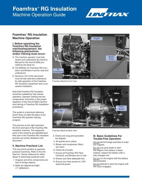
Engine<br />
I. Before operating the<br />
<strong>Foamfrax</strong> <strong>RG</strong> <strong>Insulation</strong><br />
machine/equipment, the<br />
following precautions<br />
and/or training must occur:<br />
A. The machine operator must fully<br />
review and understand the Owner’s<br />
Manual for the Insul 8-2000 provided<br />
by Ark Seal Inc.<br />
B. The MSDS’s for <strong>Foamfrax</strong> <strong>RG</strong> <strong>Insulation</strong><br />
and Binders must be read and<br />
understood.<br />
C. Sections I-XII of this document<br />
must be fully read and understood<br />
for safe operation of the <strong>Foamfrax</strong><br />
<strong>RG</strong> <strong>Insulation</strong> equipment and a successful<br />
installation.<br />
Air<br />
Compressor<br />
<strong>Foamfrax</strong> Machine Front View<br />
Binder<br />
Pump<br />
Note that <strong>Foamfrax</strong> <strong>RG</strong> <strong>Insulation</strong><br />
should be installed by fully trained<br />
operators. Operator training has two<br />
components: instruction in the proper<br />
operation of the Insul 8-2000 machine<br />
and training in <strong>Foamfrax</strong> <strong>RG</strong> Installation<br />
procedures.<br />
This guide is a technical reference<br />
which does not take the place of the<br />
<strong>Foamfrax</strong> <strong>RG</strong> operator training<br />
program.<br />
The pictures on the right represent<br />
the front and back of the <strong>Foamfrax</strong> <strong>RG</strong><br />
<strong>Insulation</strong> machine. The respective<br />
parts of the machine are identified and<br />
their part in the <strong>Foamfrax</strong> <strong>RG</strong> <strong>Insulation</strong><br />
process are further detailed in this<br />
document.<br />
II. Machine Precheck List<br />
This document pertains to gasoline<br />
powered machines. Refer to the Ark<br />
Seal Inc. Owner’s Manual for either<br />
diesel or electrically powered units.<br />
1. Hoppers and drive components are<br />
free of foreign objects.<br />
2. Belts are aligned and tight<br />
( 1 ⁄2" deflection).<br />
Muffler<br />
<strong>Foamfrax</strong> Machine Back View<br />
3. Chains are snug and sprockets<br />
are aligned.<br />
4. All guards are in place.<br />
5. Blower and compressor filters<br />
are clean.<br />
6. Check all oil levels.<br />
7. Ensure all <strong>Foamfrax</strong> <strong>RG</strong> Fiber,<br />
Cements, and Binders are on site.<br />
8. Ensure you have adequate fuel.<br />
9. Ensure you have access to 110V<br />
electrical power.<br />
Roots<br />
Blower<br />
III. Basic Guidelines For<br />
Trouble-Free Operation<br />
Do not permit foreign particles to enter<br />
the hoppers.<br />
Do not use jump leads to start<br />
the engine if the battery is dead.<br />
Instead, replace the battery with a<br />
fully charged unit.<br />
Do not run the engine with the battery<br />
disconnected.<br />
Do not attempt to start the engine with<br />
the clutch engaged.
Do not feed any wet materials into<br />
the hoppers.<br />
Do not run the engine with the air<br />
cleaner removed.<br />
Do not let binder freeze.<br />
Flush lines, fittings, and nozzles<br />
before getting started.<br />
Clean inside of <strong>Foamfrax</strong> <strong>RG</strong> <strong>Insulation</strong><br />
mixing chamber with water.<br />
Keep binder barrel covered.<br />
Keep blowing hose as straight as<br />
possible, no loops.<br />
Make sure to use <strong>Foamfrax</strong> <strong>RG</strong> <strong>Insulation</strong><br />
stand with mixing chamber.<br />
IV. Recommended<br />
Maintenance Schedule<br />
DAILY<br />
Check all oil levels, (engine, blower,<br />
compressor, pump).<br />
Check pulley and sprocket alignment.<br />
Check blower and compressor filters.<br />
EVERY 25 HOURS<br />
• Service the air filter.<br />
EVERY 50 HOURS<br />
• Check hoses on machine.<br />
• Check torque on clutch retaining bolt.<br />
• Check belt and chain tension.<br />
• Clean cooling fins on engine and<br />
compressor.<br />
• Change engine oil.<br />
EVERY 100 HOURS<br />
• Clean or replace spark plugs in engine.<br />
• Check torque on engine head bolts<br />
(18-20 ft lbs.).<br />
• Check compressor oil.<br />
• Change engine filter.<br />
EVERY 200 HOURS<br />
• Check paddle wheel seals.<br />
• Change pump oil.<br />
• Change engine filter.<br />
• Change engine points and condenser.<br />
EVERY 1000 HOURS<br />
• Change blower oil.<br />
• Lightly grease all bearings.<br />
V. Safety Guidelines<br />
• Do not put your hands inside the<br />
hoppers before disconnecting the<br />
on/off control lead and switching off<br />
the engine.<br />
• Do not operate the machine unless all<br />
the guards are securely fixed in their<br />
correct positions.<br />
• Do not smoke or use naked lights in<br />
the vicinity of the fuel tank.<br />
• Do not install fibrous cement<br />
materials without wearing suitable<br />
respiratory protection.<br />
• Do not put your hand through the<br />
inspection window without first<br />
switching off the engine.<br />
• Do not leave the battery on the<br />
machine when carrying out repairs<br />
with electric arc welding equipment.<br />
• Do not fill the fuel tank when the<br />
engine is running. Petrol fumes can<br />
ignite causing fire and explosion.<br />
• Leave space in the fuel tank for<br />
expansion.<br />
VI. Periodic Maintenance<br />
Procedures<br />
Never Work On Machine Unless<br />
Spark Plug Cable Has Been<br />
Disconnected.<br />
1. Check oil level regularly.<br />
2. Change oil after first 5 hours of<br />
operation, then after every 50 hours<br />
of operation.<br />
3. Clean and re-oil foam element in<br />
air cleaner after every 25 hours of<br />
operation. Remove foam element.<br />
Wash in liquid detergent and water.<br />
Squeeze dry. Soak in engine oil<br />
and squeeze to remove excess.<br />
Reassemble air cleaner.<br />
4. Replace or clean paper cartridge in<br />
air cleaner after every 100 hours of<br />
operation.<br />
5. Clean and check spark plug gap<br />
after every 100 hours of operation.<br />
6. Clean exterior and all accessible<br />
areas of machine thoroughly using<br />
HEPA vacuum, brush or rag.<br />
VII. Troubleshooting<br />
ENGINE<br />
Refer to the engine manual. Remember,<br />
for service under warranty the unit<br />
must be taken to an authorized service<br />
dealer.<br />
BLOWER<br />
Blowers are known for giving excellent<br />
service for many years. They are<br />
guaranteed by the manufacturer.<br />
Should your blower unit become<br />
unusually noisy or show other indication<br />
of being defective within a short<br />
period of time, we suggest you contact<br />
us. DO NOT ATTEMPT ANY REPAIRS<br />
YOURSELF. Special training and special<br />
tools are required to repair these units.<br />
ELECTRIC CLUTCH<br />
Should you encounter slippage or observe<br />
the clutch running hot, check for:<br />
1. Low battery.<br />
2. Short or break in wiring.<br />
3. Charging system not functioning.<br />
Should you encounter failure to<br />
engage, check for:<br />
1. Faulty wiring or connections.<br />
2. Short or break in remote control cord.<br />
3. Dead battery.<br />
4. Broken switch or receptacle.<br />
EXCESS AIR<br />
Should you encounter too much air<br />
pressure, check for:<br />
1. Plugged air by-pass valve.<br />
2. Engine running too fast.<br />
PUMP<br />
Check operation manual for diaphragm<br />
pump. See the specific section in the<br />
pump manual for troubleshooting giving<br />
probable causes and corrective action.<br />
GENERAL<br />
Should you encounter sudden<br />
reduction or loss of air, check for:<br />
1. A broken butterfly plate inside the<br />
air line check valve.<br />
2. A loose hose connection.<br />
3. Plugged hose.<br />
4. Broken engine or blower belts.<br />
5. Open bypass valve.<br />
6. Inoperative clutch.<br />
7. Slow engine rpm.<br />
Should you encounter sudden stoppage<br />
of the material flow, check for:<br />
1. Slow engine rpm.<br />
2. Correct opening of the material<br />
control slide (open too far).<br />
3. Slippage of the belt.<br />
4. Worn feeder seals.<br />
5. Worn or leaking hose.<br />
6. Overcompression of the Fiber in the<br />
feed hopper by the material loader.<br />
7. Improperly opened air bypass.
VIII. Machine Set-Up<br />
Tools Required<br />
• Flat Head Screwdriver<br />
• Lid off for opening pails<br />
• Sharp Knife<br />
• Flat trowel (optional)<br />
Job Site Requirements<br />
• Water source and hose<br />
• Personal protective equipment<br />
• 110V electrical power<br />
• Proper ventilation for engine exhaust<br />
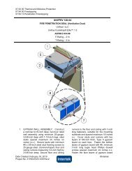
A. FIBER HOSES<br />
1<br />
Connect the 3" (76mm) diameter hose<br />
to the machine outlet. All hoses that<br />
will carry dry fiber must be double<br />
clamped and the fasteners checked<br />
for tightness.<br />
4<br />
Connect the mixing chamber to the<br />
mixing chamber stand. It is imperative<br />
that the mixing chamber remains on a<br />
downward slant, with the shooting hose<br />
side at the lowest elevation.<br />
7<br />
Connect the red binder/air hose to the<br />
mixing chamber. Note that the use of<br />
two different fittings prevents crossing<br />
the air and binder lines.<br />
2<br />
Connect the 2 1 ⁄2" (64mm) diameter<br />
hose to 3" (76mm) diameter hose<br />
using the reducer provided. Ensure<br />
that both connections are double<br />
clamped and fasteners checked for<br />
tightness. For complete conditioning of<br />
the fiber, at least 25' (7.6m) of each<br />
hose size should be used.<br />
5<br />
Connect the 2" (51mm) diameter working<br />
hose to the outlet of the mixing<br />
chamber. This hose will be used to gun<br />
the <strong>Foamfrax</strong> <strong>RG</strong> material and must be<br />
fitted with an approximate 2' (610mm)<br />
length of PVC pipe on the terminal end<br />
for use as a nozzle.<br />
3<br />
Connect the 2 1 ⁄2" (64mm) diameter<br />
hose to the mixing chamber fiber inlet.<br />
Note that this connection must be<br />
double clamped as well.<br />
B. BINDER AND AIR HOSES<br />
6<br />
Connect the red binder/air hose to the<br />
machine. Note that each hose has a<br />
different size fitting, so the hose can<br />
only fit the binder and air connections<br />
in one way.<br />
C. OTHER CONNECTIONS<br />
8<br />
Connect the fuel container. Note that<br />
for proper fuel delivery, the container<br />
vent must be opened. This vent must<br />
be closed at the completion of each<br />
day.
9<br />
Connect the on/off switch (black cord)<br />
into the lower plug on the front of the<br />
machine. Note that pulling this plug<br />
at any time will immediately stop the<br />
equipment.<br />
12 15<br />
Completely close the binder flow<br />
needle valve, then open 3 turns. This<br />
valve is either opened or closed to<br />
adjust the <strong>Foamfrax</strong> <strong>RG</strong> <strong>Insulation</strong><br />
consistency. The binder flow is the<br />
only variable to be adjusted to<br />
change the <strong>Foamfrax</strong> <strong>RG</strong> <strong>Insulation</strong><br />
consistency.<br />
The back gate for fiber flow is completely<br />
closed. For proper material flow rates,<br />
open this gate 17 full turns to allow fiber<br />
to exit the machine.<br />
10<br />
Connect the vacuum system to the<br />
machine hood. Note that the vacuum<br />
must be run at all times while fiber is<br />
being loaded and when the fiber feed<br />
mechanism is engaged.<br />
13<br />
The pressure gauge is used to confirm<br />
binder pressure at the mixing chamber.<br />
When the motor/engine is running,<br />
binder pressure should be greater than<br />
150 psi.<br />
16<br />
Rods are supplied in the fiber conditioning<br />
chamber to control the fiber<br />
dwell time (the time the fiber is<br />
conditioned within the machine). With<br />
the <strong>Foamfrax</strong> <strong>RG</strong> <strong>Insulation</strong> process,<br />
5 rods are used. Starting at the end,<br />
put one rod in every other opening.<br />
D. MIXING CHAMBER<br />
SETTINGS<br />
11<br />
Completely close the air pressure<br />
valve, then open it 1 ⁄16 of a turn.<br />
E. MACHINE SETTINGS<br />
14<br />
The front gate which controls fiber<br />
flow is completely closed. For proper<br />
material flow rates, open this gate<br />
13 full turns to allow fiber to exit the<br />
machine.<br />
17<br />
The Roots blower that moves the fiber<br />
can be adjusted to control air volume.<br />
With the <strong>Foamfrax</strong> <strong>RG</strong> <strong>Insulation</strong><br />
process, this valve must be completely<br />
closed for maximum pressure.
F. CEMENT HOPPER SETTINGS<br />
18<br />
Plug the cement hopper control box<br />
into 110V power supply and turn switch<br />
from off to on.<br />
19<br />
Using the up or down arrows, set the<br />
cement hopper control box to 60Hz.<br />
21<br />
Check the air compressor oil. The compressor<br />
uses 10W-30 non-detergent oil.<br />
IX. Binder Preparation<br />
22<br />
The binder for <strong>Foamfrax</strong> <strong>RG</strong> <strong>Insulation</strong><br />
is field mixed and consists of water,<br />
<strong>Foamfrax</strong> “<strong>RG</strong>” Binder, and <strong>Foamfrax</strong><br />
“B” Binder. The mix ratio is:<br />
3.5 gallons water (13.2L)<br />
1 pint ( 1 ⁄8 gallon) “B” Binder (.47L)<br />
.83 gallon “<strong>RG</strong>” Binder (3.2L)<br />
To utilize a full 55-gallon (208L) binder<br />
container, this ratio is multiplied by 12.<br />
Therefore, it requires 42.5 gallons<br />
(161L) of water, 1.5 gallons (5.7L) of<br />
“B” Binder, and 10 gallons (37.9L) of<br />
“<strong>RG</strong>” Binder.<br />
Hot water, if available, works best to<br />
make binder. In all cases, it is recommended<br />
that the binder temperature be<br />
above 50°F. The mix sequence is to fill<br />
the tank with water, add the “B” Binder<br />
and stir, then add the “<strong>RG</strong>” Binder and<br />
stir. The binder tank should be covered<br />
to keep out any particulate.<br />
23<br />
After the binder mix is complete, the<br />
binder intake hose may be submerged<br />
into the tank. The binder hose will be<br />
supplied weighted; however, some<br />
additional weight may be required at<br />
the end of the intake hose to keep it at<br />
the bottom of the binder tank. The<br />
screened intake of the binder hose<br />
must remain free and clear of all<br />
particulate to maintain the optimal<br />
binder flow.<br />
X. Machine Start Up<br />
24<br />
Once steps 1-23 have been completed,<br />
the machine can be started. Using the<br />
ignition switch and choke, start the<br />
engine. The engine should be adjusted<br />
so it operates at an idle RPM of 2800.<br />
G. MISCELLANEOUS<br />
20<br />
Check the engine oil. The gasoline<br />
engine uses 10W-30 oil and should be<br />
checked at the start of each job and<br />
once more throughout the day.<br />
25<br />
Once the machine is running and the<br />
choke is disengaged, binder pressure<br />
will build. Check the binder pump<br />
pressure gauge and adjust to 150 psi<br />
or 11 – 12 bar. If there is no pressure,<br />
flip the re-circulate switch at the pump<br />
to gain prime, then toggle the recirculate<br />
switch back to pressurize the<br />
binder hose.
XI. Fiber Loading<br />
26<br />
The <strong>Foamfrax</strong> <strong>RG</strong> <strong>Insulation</strong> machine<br />
has been modified to minimize potential<br />
airborne fiber exposure while loading<br />
the bulk fiber. These modifications<br />
include the hood enclosure and vacuum<br />
exhaust system. While the <strong>Foamfrax</strong><br />
<strong>RG</strong> <strong>Insulation</strong> machinery is in operation,<br />
the vacuum exhaust system<br />
must be on.<br />
29<br />
The fiber is then pushed into the<br />
machine hopper and the hood enclosure<br />
door is closed. When not loading<br />
fiber into the machine, this door<br />
must remain closed.<br />
XII. Machine Operation<br />
32 33 34 35 36 37<br />
The sequence for gunning <strong>Foamfrax</strong><br />
<strong>RG</strong> <strong>Insulation</strong> is to first turn on the<br />
binder at the mixing chamber (32).<br />
Next, energize the blower clutch to<br />
deliver the fiber to the mixing chamber<br />
(33). The control for the machinery has<br />
two on/off switches; one controls the<br />
blower clutch only, the other controls<br />
the moving components to deliver<br />
fiber. Press the start button on the<br />
cement hopper control panel once<br />
material begins to flow through the<br />
shooting hose to engage cement feed<br />
(34). To stop the <strong>Foamfrax</strong> <strong>RG</strong> <strong>Insulation</strong><br />
gunning process, press the stop<br />
button on the cement hopper control<br />
panel to disengage the cement feed<br />
(35). Turn off the blower clutch (36),<br />
then turn off the binder at the mixing<br />
chamber (37). Note that a special air<br />
piston has been wired/plumbed into<br />
the equipment, which only allows the<br />
delivery of fiber if the liquid binder is<br />
flowing into the mixing chamber. The<br />
blower motor will not turn on to deliver<br />
dry fiber only.<br />
30 31<br />
32<br />
27<br />
The proper way to load the bulk fiber<br />
in order to minimize airborne fiber<br />
potential is to use a sharp knife and<br />
cut 3 sides at one end of the bag.<br />
When properly cut, the end of the fiber<br />
bag will hinge up as illustrated in the<br />
photograph.<br />
If the upper hopper chamber is<br />
attached, remove and set aside. Once<br />
the hopper is removed, add cement to<br />
the lower cement chamber. Plug the<br />
powder injector drive controller into<br />
110V power and set at 60HZ.<br />
33<br />
Off<br />
On<br />
On<br />
On<br />
28<br />
Next, the bag is rested onto the edge<br />
of the machine hood and a diagonal<br />
cut is made across the bag face.
34<br />
With experience, a feel for the proper<br />
<strong>Foamfrax</strong> <strong>RG</strong> <strong>Insulation</strong> consistency is<br />
established by the operator.<br />
35<br />
39<br />
Once material is flowing consistently,<br />
a density check is required. Also, a<br />
check to ensure the fiber/cement/<br />
binder ratio is correct is required.<br />
Weigh an empty 5 gallon pail. Note that<br />
an empty “<strong>RG</strong>” Binder pail must be<br />
used for this density check. A bathroomtype<br />
scale works well for this.<br />
42<br />
Keeping the nozzle end 3 feet from<br />
the impact surface, begin gunning<br />
<strong>Foamfrax</strong> <strong>RG</strong> <strong>Insulation</strong> into the pail<br />
and completely fill it. Time how long it<br />
takes to fill the bucket. The bucket<br />
should take 100 seconds + 15 seconds<br />
to fill.<br />
36<br />
43<br />
Use a trowel or straightedge to scrape<br />
off any excess material.<br />
37<br />
Off<br />
On<br />
40<br />
Fill lower cement hopper full and trowel<br />
smooth.<br />
38<br />
Off<br />
Off<br />
In order to adjust the <strong>Foamfrax</strong> <strong>RG</strong><br />
<strong>Insulation</strong> consistency, material<br />
should be gunned into an empty pail or<br />
garbage can to establish a consistent<br />
flow. The amount of binder introduced<br />
into the system should be adjusted to<br />
yield a product which is homogeneous<br />
and neither too foamy nor too dry.<br />
41<br />
Pour some of the binder solution into a<br />
<strong>Foamfrax</strong> <strong>RG</strong> Binder pail, filling it 3 ⁄4 full.<br />
Mark the starting level of the binder.<br />
44<br />
Re-weigh the pail with the <strong>Foamfrax</strong><br />
<strong>RG</strong> <strong>Insulation</strong> in it, and subtract the<br />
weight of the empty pail. The target<br />
weight of this material is 30 lbs<br />
(480 kg) nominal, + 3 lbs (48 kg).<br />
If the weight does not fall in this range,<br />
adjust the binder amount (more binder<br />
= lower density, less binder = higher<br />
density) and retest until the target<br />
weight is achieved.<br />
Note that the <strong>Foamfrax</strong> <strong>RG</strong> <strong>Insulation</strong><br />
System has been developed for<br />
optimal performance at a specified
dry density of 22-28 lbs/ft 3 (352-448<br />
kg/m 3 ). Installation of <strong>Foamfrax</strong> <strong>RG</strong><br />
<strong>Insulation</strong> at densities above or below<br />
this specification range will effect the<br />
thermal and mechanical performance<br />
of the product, and may increase<br />
airborne fiber levels on the jobsite.<br />
45 46<br />
The correct dry ratio for fiber:binder is<br />
2:1 by weight. To determine the amount<br />
of fiber, use the following formula:<br />
Fiber (lbs) = Finished <strong>RG</strong> Product<br />
44 (lbs) - Binder Solution 47 (lbs) -<br />
Cement 48 (lbs)<br />
The calculated amount of Fiber to<br />
Cement should be 2:1 + 10%.<br />
47<br />
Weight (Lbs)<br />
Binder Solution Calibration<br />
20<br />
18<br />
16<br />
14<br />
12<br />
10<br />
8<br />
6<br />
4<br />
2<br />
0<br />
0 1 2 3 4 5 6<br />
Drop in Binder (in)<br />
49 50<br />
Reattach upper cement hopper and<br />
refill with cement. Note that <strong>Foamfrax</strong><br />
<strong>RG</strong> Cement is supplied in 94 lb bags.<br />
A scoop or some other means must be<br />
used to load the <strong>Foamfrax</strong> <strong>RG</strong> Cement<br />
so that the load weight remains within<br />
OSHA guidelines.<br />
Once the density check is complete,<br />
measure the drops in the cement<br />
hopper (45) and binder pail (46). The<br />
cement drop should be 1 9 ⁄16" (40mm)<br />
+ 5<br />
⁄32" (14mm). The binder drop should<br />
be 4 1 ⁄8" (105mm) + 3<br />
⁄8" (10mm). These<br />
are the amounts for filling one 5-gallon<br />
<strong>RG</strong> Binder pail with finished product.<br />
46<br />
48<br />
Weight (Lbs)<br />
20<br />
18<br />
16<br />
14<br />
12<br />
10<br />
8<br />
6<br />
4<br />
2<br />
0<br />
Cement Calibration<br />
0 1 2 3 4 5 6<br />
Cement Drop from top (in)<br />
To answer additional questions about<br />
<strong>Foamfrax</strong> <strong>RG</strong> <strong>Insulation</strong> machine operations,<br />
material handling procedures, or<br />
<strong>Foamfrax</strong> <strong>RG</strong> <strong>Insulation</strong> lining design,<br />
please contact the <strong>Unifrax</strong> Corporation<br />
Application Engineering Department at<br />
716-278-3888. For specific machine<br />
repair issues, replacement parts, etc.,<br />
please contact Ark Seal LLC at<br />
1-800-525-8992.<br />
Once steps 1-48 have been completed,<br />
the <strong>Foamfrax</strong> <strong>RG</strong> <strong>Insulation</strong> is ready<br />
for installation. Please refer to the<br />
<strong>Foamfrax</strong> <strong>Insulation</strong> Installation<br />
Guidelines Document for specific<br />
installation techniques.<br />
Form C-4024<br />
Effective 6/04<br />
©2003, <strong>Unifrax</strong> Corporation<br />
All Rights Reserved<br />
Printed in U.S.A.<br />
The following is a registered trademark of <strong>Unifrax</strong> Corporation: <strong>Foamfrax</strong>.<br />
The <strong>Foamfrax</strong> <strong>Insulation</strong> Technology is protected under the following<br />
U.S. Patents: 4,768,710, 4,978,252, 5,131,590<br />
<strong>Unifrax</strong> Corporation<br />
Corporate Headquarters<br />
2351 Whirlpool Street<br />
Niagara Falls, New York 14305-2413<br />
Telephone: 716-278-3800<br />
Telefax: 716-278-3900<br />
Internet: www.unifrax.com<br />
Email: info@unifrax.com