Stratigraphic Modeling Tools in MineSight Part 3 - Mintec, Inc.
Stratigraphic Modeling Tools in MineSight Part 3 - Mintec, Inc.
Stratigraphic Modeling Tools in MineSight Part 3 - Mintec, Inc.

You also want an ePaper? Increase the reach of your titles
YUMPU automatically turns print PDFs into web optimized ePapers that Google loves.
<strong>Stratigraphic</strong> <strong>Model<strong>in</strong>g</strong> <strong>Tools</strong> <strong>in</strong> M<strong>in</strong>eSight <strong>Part</strong> 3<br />
In <strong>Part</strong>s 1 and 2 of this series we looked at the stratigraphic tools <strong>in</strong> M<strong>in</strong>eSight and how they can be used for model<strong>in</strong>g<br />
stratigraphic deposits like coal and bauxite. In this f<strong>in</strong>al <strong>in</strong>stalment we look at how these tools could be used <strong>in</strong> a nonstratigraphic<br />
environment.<br />
It is important to remember that stratigraphic models are a regular grid that stores numbers. This could be an elevation,<br />
thickness, slope, quality or some other recorded value. The fact that multiple, stacked, grids can exist <strong>in</strong> the same model<br />
all of a sudden allows you to do some pretty creative th<strong>in</strong>gs with some very basic math.<br />
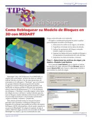
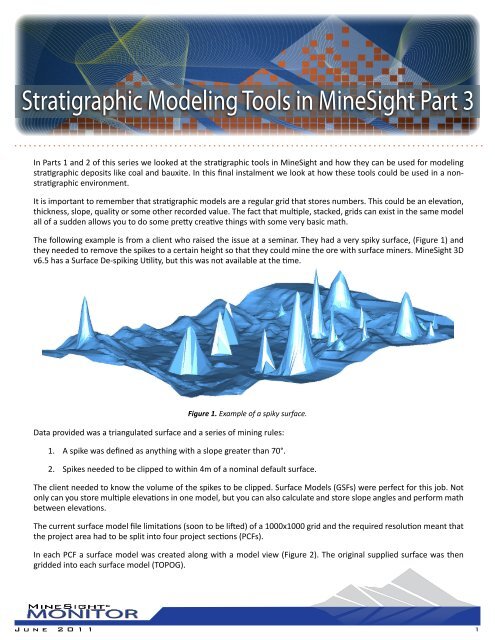
The follow<strong>in</strong>g example is from a client who raised the issue at a sem<strong>in</strong>ar. They had a very spiky surface, (Figure 1) and<br />
they needed to remove the spikes to a certa<strong>in</strong> height so that they could m<strong>in</strong>e the ore with surface m<strong>in</strong>ers. M<strong>in</strong>eSight 3D<br />
v6.5 has a Surface De-spik<strong>in</strong>g Utility, but this was not available at the time.<br />
Figure 1. Example of a spiky surface.<br />
Data provided was a triangulated surface and a series of m<strong>in</strong><strong>in</strong>g rules:<br />
1. A spike was def<strong>in</strong>ed as anyth<strong>in</strong>g with a slope greater than 70°.<br />
2. Spikes needed to be clipped to with<strong>in</strong> 4m of a nom<strong>in</strong>al default surface.<br />
The client needed to know the volume of the spikes to be clipped. Surface Models (GSFs) were perfect for this job. Not<br />
only can you store multiple elevations <strong>in</strong> one model, but you can also calculate and store slope angles and perform math<br />
between elevations.<br />
The current surface model file limitations (soon to be lifted) of a 1000x1000 grid and the required resolution meant that<br />
the project area had to be split <strong>in</strong>to four project sections (PCFs).<br />
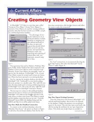
In each PCF a surface model was created along with a model view (Figure 2). The orig<strong>in</strong>al supplied surface was then<br />
gridded <strong>in</strong>to each surface model (TOPOG).<br />
June 2011 1
Figure 2. Creation of a new surface model with the items required for this project.<br />
The next step was to create a nom<strong>in</strong>al default surface (DEF). This is an imag<strong>in</strong>ary surface based on the orig<strong>in</strong>al surface,<br />
m<strong>in</strong>us the spikes. Because we could not use the upcom<strong>in</strong>g M<strong>in</strong>eSight 3D De-spik<strong>in</strong>g Utility we had to use a bit of <strong>in</strong>genuity.<br />
Us<strong>in</strong>g the General Gridder Tool from the Po<strong>in</strong>t menu, we draped a 10x10m grid of po<strong>in</strong>ts onto the orig<strong>in</strong>al surface. We<br />
assumed that it was very unlikely that any of these po<strong>in</strong>ts would land on a spike. As it happened, a few did but these were<br />
easily deleted manually <strong>in</strong> a side on view.<br />
These po<strong>in</strong>ts were then exported to an ASCII file and gridded to the surface model us<strong>in</strong>g the M<strong>in</strong>eSight Compass procedure<br />
PDHGRD.DAT (Grid DHs us<strong>in</strong>g DTM/Gradient). The Gradient <strong>in</strong>terpolation method produced the best results with this<br />
data. To ensure that the nom<strong>in</strong>al surface did not go above the real topography, the surface was normalized us<strong>in</strong>g the<br />
procedure GRDRAT.DAT (Rationalize Gridded Surfaces). The results are shown <strong>in</strong> Figure 3.<br />
Figure 3. Section view of the two surfaces after they have been normalized.<br />
The maximum slope of the orig<strong>in</strong>al topography (MAX) was then calculated us<strong>in</strong>g procedure GRDSLP.DAT (Calculate<br />
Gridded Slopes <strong>in</strong> GSM). And procedure P61201.DAT (User-Calcs Model) was used to calculate the thickness between<br />
the orig<strong>in</strong>al and default surfaces (THICK) (Figure 4). The orig<strong>in</strong>al surface elevations were also copied <strong>in</strong>to a new item,<br />
(UPD) aga<strong>in</strong> us<strong>in</strong>g P61201.DAT, so that they could be edited.<br />
June 2011 2
m i n e s i g h t ®<br />
Figure 4. TOPOG colored by the max slope (MAX) and thickness (THICK).<br />
The f<strong>in</strong>al calculation necessary was to set the new surface elevations to the nom<strong>in</strong>al surface plus 4m, wherever the slope<br />
was greater than 70° and the thickness was greater than 4m, us<strong>in</strong>g procedure P61201.DAT aga<strong>in</strong>.<br />
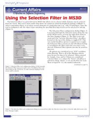
It is then a simple exercise to generate the solid shapes that were the difference between TOPOG and the f<strong>in</strong>al result<br />
(UPD) item us<strong>in</strong>g the Intersect Surfaces Tool <strong>in</strong> M<strong>in</strong>eSight 3D (Figure 5). You don’t even have to export the surfaces to an<br />
.MSR file because the Intersect Surfaces Tool can read directly from the surface model (also from LGOs).<br />
Figure 5. UPD surface and the resultant solids displayed us<strong>in</strong>g Hard Edges.<br />
A little knowledge and some out-of-the-box th<strong>in</strong>k<strong>in</strong>g turn tools designed for stratigraphic model<strong>in</strong>g <strong>in</strong>to a solution that<br />
would be very hard to obta<strong>in</strong> with triangulations. Next time you have surfaces that need manipulat<strong>in</strong>g, consider the<br />
stratigraphic model<strong>in</strong>g tools <strong>in</strong> M<strong>in</strong>eSight. For help, call your local technical support team at M<strong>in</strong>tec, <strong>Inc</strong>.<br />
www.m<strong>in</strong>esight.com<br />
June 2011 3