Foamfrax Installation Story #1 - Unifrax
Foamfrax Installation Story #1 - Unifrax
Foamfrax Installation Story #1 - Unifrax

Create successful ePaper yourself
Turn your PDF publications into a flip-book with our unique Google optimized e-Paper software.
<strong>Installation</strong> <strong>Story</strong> <strong>#1</strong><br />
<strong>Foamfrax</strong> TM ® Insulation<br />
Industry:<br />
Ceramic<br />
Location:<br />
Northeast United States<br />
<strong>Installation</strong> Date: April 2001<br />
Operating Temperature: 1500°F (815°C)<br />
Scope of Job:<br />
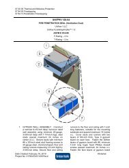
Rotary Calciner Throat Section<br />
3” (76mm) Thick, 8 PCF (128 kg/m 3 ), <strong>Foamfrax</strong> Grade I<br />
Veneer Over Existing Module Lining<br />
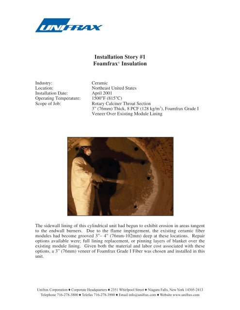
The sidewall lining of this cylindrical unit had begun to exhibit erosion in areas tangent<br />
to the endwall burners. Due to the flame impingement, the existing ceramic fiber<br />
modules had become grooved 3”– 4” (76mm-102mm) deep at these locations. Repair<br />
options available were; full lining replacement, or pinning layers of blanket over the<br />
existing module lining. Given both the material and labor cost associated with these<br />
options, a 3” (76mm) veneer of <strong>Foamfrax</strong> Grade I Fiber was chosen and installed in this<br />
unit.<br />
<strong>Unifrax</strong> Corporation ◆ Corporate Headquarters ◆ 2351 Whirlpool Street ◆ Niagara Falls, New York 14305-2413<br />
Telephone 716-278-3800 ◆ Telefax 716-278-3900 ◆ Email info@unifrax.com ◆ Website www.unifrax.com
For installation over existing ceramic fiber<br />
lining systems, the only surface<br />
preparation required is to remove any<br />
loose or devitrified material on the lining<br />
hot face. For the removal of any after<br />
service refractory material, refer to the<br />
product MSDS for proper material<br />
handling guidelines. To minimize any<br />
potential airborne fiber levels during this<br />
procedure, the lining should be thoroughly<br />
wet with water before the loose material is<br />
removed.<br />
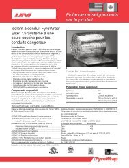
Prior to installation of the <strong>Foamfrax</strong> material, the lining should be re-wet with water.<br />
When gunning <strong>Foamfrax</strong> Insulation on the lining surface, the recommended nozzle<br />
distance is 2’ - 3’ (610mm-915mm) from the work surface. Allow the material to fill any<br />
pockets/voids and work towards an even surface on the hot face.<br />
After the <strong>Foamfrax</strong> lining veneer has been<br />
installed, use a trowel to smooth the<br />
finished surface. Occasionally wetting the<br />
trowel allows it to flow freely over the<br />
<strong>Foamfrax</strong> material as it is troweled. Note:<br />
There is no critical heat-up/cure-out for<br />
<strong>Foamfrax</strong> Insulation. This unit was put<br />
into service immediately after installation,<br />
using the customers normal start up<br />
procedure.<br />
With the installation of <strong>Foamfrax</strong> Insulation, the following customer benefits were<br />
realized:<br />
• Turnkey <strong>Installation</strong><br />
- A specially trained <strong>Unifrax</strong> distributor/contractor was able to supply<br />
materials, equipment, and installation as a complete package.<br />
• Fuel Efficiency<br />
- The additional lining thickness of <strong>Foamfrax</strong> Insulation served to<br />
further lower heat loss and heat storage values.<br />
• Extended Service Life<br />
- The <strong>Foamfrax</strong> Insulation upgrade provided extended service life for<br />
the calciner and avoided a complete lining replacement and costly<br />
downtime.<br />
• <strong>Installation</strong> Speed<br />
- The complete <strong>Foamfrax</strong> <strong>Installation</strong> was completed in four hours,<br />
resulting in reduced furnace downtime and increased productivity.<br />
Form C-4005-A