EE 6313 Homework Assignments 1. Homework I: Chapter 1: 1.2, 1.5 ...
EE 6313 Homework Assignments 1. Homework I: Chapter 1: 1.2, 1.5 ...
EE 6313 Homework Assignments 1. Homework I: Chapter 1: 1.2, 1.5 ...

Create successful ePaper yourself
Turn your PDF publications into a flip-book with our unique Google optimized e-Paper software.
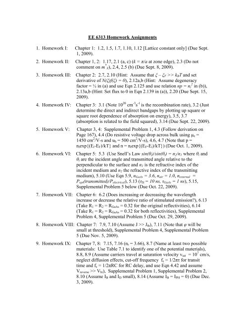
<strong>EE</strong> <strong>6313</strong> <strong>Homework</strong> <strong>Assignments</strong><br />
<strong>1.</strong> <strong>Homework</strong> I: <strong>Chapter</strong> 1: <strong>1.</strong>2, <strong>1.</strong>5, <strong>1.</strong>7, <strong>1.</strong>10, <strong>1.</strong>12 [Lattice constant only] (Due Sept.<br />
1, 2009).<br />
2. <strong>Homework</strong> II: <strong>Chapter</strong> 1, 2: <strong>1.</strong>17, 2.1 (a, c) (k = π/a at zone edge), 2.3 (Do not<br />
comment on m * X), 2.4, 2.5 (b) (Due Sept. 8, 2009).<br />
3. <strong>Homework</strong> III: <strong>Chapter</strong> 2: 2.7, 2.10 (Hint: Assume that ξ – ξ F >> k B T and set<br />
derivative of N(ξ)f(ξ) = 0), 2.12a,b (Hint: Assume degeneracy<br />
factor = ½ in (a) and use Eqn 2.125 and use relation np = n 2 i in (b)),<br />
2.13a,b (Hint: Set flux to 0 in Eqn 2.139 in (a)), 2.20 (Due Sept. 15,<br />
2009).<br />
4. <strong>Homework</strong> IV: <strong>Chapter</strong> 3: 3.1 (Note 10 20 cm -3 s -1 is the recombination rate), 3.2 (Just<br />
determine the direct and indirect bandgaps by plotting up square or<br />
square root dependence of absorption on energy), 3.5, 3.7<br />
(absorption is related to the field squared), 3.14 (Due Sept. 22, 2009).<br />
5. <strong>Homework</strong> V: <strong>Chapter</strong> 3, 4: Supplemental Problem 1, 4.3 (Follow derivation on<br />
Page 167), 4.4 (Do resistive voltage drop across bulk using μ e =<br />
1450 cm 2 /V-s and u h = 500 cm 2 /V-s), 4.6, 4.7 (Note that p =<br />
n i exp{(E i -E F )/kT} and n = n i exp{(E F -E i )/kT}) (Due Oct. 1, 2009).<br />
6. <strong>Homework</strong> VI: <strong>Chapter</strong> 5: 5.3 (Use Snell’s Law sin(θ i )/sin(θ t ) = n 2 /n 1 where θ i and<br />
θ t are the incident angle and transmitted angle relative to the<br />
perpendicular to the surface and n 1 is the refractive index of the<br />
incident medium and n 2 the refractive index of the transmitting<br />
medium), 5.10 (Use Eqn 5.9, n GaAs = 3.6, n air = <strong>1.</strong>0, n external =<br />
P opt (transmitted)/P electrical ), 5.13 (τ Si = 10 ns, τ GaAs = 1 ns), 5.15,<br />
Supplemental Problem 5 below (Due Oct. 22, 2009).<br />
7. <strong>Homework</strong> VII: <strong>Chapter</strong> 6: 6.2 (Does increasing or decreasing the wavelength<br />
increase or decrease the relative ratio of stimulated emission?), 6.13<br />
(Take R 1 = R 2 = R GaAs = 0.32 for the original reflectivities), 6.14<br />
(Take R 1 = R 2 = R GaAs = 0.32 for both reflectivities), Supplemental<br />
Problem 4, Supplemental Problem 5 (Due Oct. 29, 2009).<br />
8. <strong>Homework</strong> VIII: <strong>Chapter</strong> 7: 7.9, 7.10 (Assume J >> J th ), 7.11 (Note that φ will be<br />
small at threshold), Supplemental Problem 4, Supplemental Problem<br />
5 (Due Nov. 5, 2009).<br />
9. <strong>Homework</strong> IX: <strong>Chapter</strong> 7, 8: 7.15, 7.16 (n r = 3.66), 8.7 (Name at least two possible<br />
materials: Use Table 7.1 to identify one of the potential materials),<br />
8.8, 8.9 (Assume carriers travel at saturation velocity v sat = 10 7 cm/s,<br />
neglect diffusion effects, cut-off frequency f c = 1/2πτ for transit<br />
time and f c = 1/2πRC for RC delay, and use Eqn 4.42 and assume<br />
V reverse >> V bi ), Supplemental Problem 1, Supplemental Problem 2,<br />
8.10 (Assume I B and I D small), 8.14 (Assume I B = I PH = 0) (Due Dec.<br />
3, 2009).
10. <strong>Homework</strong> X: <strong>Chapter</strong> 8, 11: 8.11 (Note avalanche gain is equivalent to<br />
multiplication factor M), Supplemental Problem 1, 1<strong>1.</strong>7. 1<strong>1.</strong>8<br />
(Please complete by Dec. 7, 2009 and will post answers online).
<strong>Homework</strong> V<br />
Problem 1:<br />
A 100 μm long by 0.50 μm wide by 0.25 μm high nanophotonic InP waveguide is<br />
forward injected with an electron-hole plasma with a concentration of 5.0 x 10 17 cm -3<br />
electron-hole pairs/cm -3 . This plasma will cause a refractive index shift of -0.004 which<br />
can be used to modulate an extremely compact 100 μm long Mach-Zehnder<br />
interferometer. Calculate the recombination rate across this waveguide using the<br />
equation given for recombination at the end of the <strong>Chapter</strong> 3 Lecture assuming that<br />
Δn = Δp = 5 x 10 17 cm -3<br />
τ h = 20 ns<br />
τ e = 1 ns<br />
Surface recombination only occurs across the top and bottom of the 0.25 μm-thick device<br />
v h = v e = 5.0 x 10 3 cm/s<br />
B = 2.5 x 10 -10 cm 3 /s<br />
C = <strong>1.</strong>0 x 10 -30 cm 6 /s<br />
and assuming that the equilibrium carrier concentrations n i and p i and the trap densities n l<br />
and p l are all small and can safely be ignored. Also, assume high level injection so Δn =<br />
Δp is much larger than the equilibrium concentration.<br />
Calculate the recombination rate due to Shockley-Read-Hall trap assisted recombination,<br />
the recombination rate due to surface recombination, the recombination rate due to<br />
radiative recombination, the recombination rate due to Auger recombination, and the total<br />
recombination rate. Report the data in terms of recombinations cm -3 s -1 . Compare these<br />
rates.<br />
Also assume that these carriers are injected across both sides of this 100 μm long by 0.25<br />
μm high device. Using the recombination rate and the volume of the waveguide and this<br />
area, calculate the current density in Amps/cm 2 . Current density is often limited to<br />
around 10 5 Amps/cm 2 because of heat and reliability reasons. How does this current<br />
density compare to this limit.<br />
<strong>Homework</strong> VI<br />
Problem 5:<br />
(a) Determine the radiative recombination efficiency η r for a GaAs p-n junction LED<br />
assuming that the light emission primarily results from electron injection and its<br />
recombination in the p-region where N A = N D = 10 18 cm -3 and assuming that B r =<br />
7.2 x 10 -10 cm 3 s -1 and that the electron nonradiative recombination lifetime is 5 x<br />
10 -9 sec (Use Eqns in Section 3.<strong>1.</strong>1 with Eqn 5.3).<br />
(b) Calculate the electron injection efficiency η i if D e = 120 cm 2 /s and D h = <strong>1.</strong>2 cm 2 /s<br />
assuming that the hole lifetime is equal to the electron lifetime (Use Eqns in<br />
Section 5.4.1).
(c) Determine the extraction efficiency η e if the overall device efficiency η o is one<br />
percent.<br />
<strong>Homework</strong> VII<br />
Problem 4:<br />
A single mode GaAs laser is to be fabricated with GaAs-Al x Ga 1-x As heterojunctions.<br />
Determine the range of the thicknesses over which this device can be designed and still<br />
give single mode operation given that the refractive index for GaAs is 3.66 and that x =<br />
0.40 for the composition of the Al x Ga 1-x As alloy with the larger refractive index in an<br />
asymmetric waveguide and also given the relation for the refractive index for Al x Ga 1-x As,<br />
n AlxGa1-xAs = 3.66 – 0.71x + 0.09x 2 . Note that single mode operation occurs between m =<br />
0 and m = 1 for an asymmetric waveguide.<br />
Problem 5:<br />
Derive the expression for A 21 /B 21 in Equation 6.24 given that B 21 = B 12 and using<br />
Planck’s black body radiation law given in Equation A6.10 in Appendix 6 and also using<br />
Equation 6.17 using g D1 = g D2 = <strong>1.</strong><br />
<strong>Homework</strong> VIII<br />
Problem 4:<br />
(a) Determine the relative change in the output wavelength caused by a small<br />
refractive index change in the laser cavity. Derive this relationship by using<br />
Equation 6.78 in order to determine the change in the wavelength of the<br />
longitudinal mode caused by the refractive index change.<br />
(b) An increase in temperature can cause a significant change in the wavelength of a<br />
WDM channel. Calculate the shift in wavelength that a 10 ºC rise would have on<br />
an InGaAsP-based laser centered at 1550 nm given that these alloys have a<br />
thermo-optic coefficient of approximately 2.0 x 10 -4 ºC -1 and a refractive index of<br />
approximately 3.4.<br />
(c) Given that the WDM channel spacing is 0.8 nm at 1550 nm, will this size of<br />
change cause a problem?<br />
Problem 5:<br />
Consider a DFB laser operating at 1550 nm. Suppose that the refractive index n = 3.4<br />
(InGaAsP). What should be the corrugation period Λ for a first order grating m = <strong>1.</strong><br />
What is Λ for a second order grating m = 2. How many corrugations are needed for a<br />
first order grating if the cavity length is 20 μm? How many corrugations are there for m<br />
= 2? Which grating would be easier to fabricate?
<strong>Homework</strong> IX<br />
Problem 1:<br />
A Si PIN photodiode has an i-Si layer of width 20 μm. The p + layer on the illumination<br />
side is very thin (0.1 μm). The PIN is reverse biased by a voltage of 100 V and then<br />
illuminated with a very short optical pulse of wavelength 900 nm. What is the duration<br />
of the photocurrent if absorption occurs over the whole i-Si layer? Use the drift velocity<br />
data for electrons and holes in silicon given below.<br />
Problem 2:<br />
A reverse biased PIN photodiode is illuminated with a short wavelength photon that is<br />
absorbed very near the surface as shown below. The photogenerated electrons have to<br />
diffuse to the depletion region where they are swept into the i-layer and drifted across.<br />
What is the speed of response of this photodiode if the i-Si layer is 20 μm and the p + layer<br />
is 1 μm and the applied voltage is 120 V? The diffusion coefficient of electrons (D e ) in<br />
the heavily doped p + region is approximately 3 x 10 -4 m 2 /s. Assume that the root mean<br />
square distance l the electrons will travel in the p + region is given by the relation l =<br />
(2D e t) 1/2 where t is the time.<br />
Diffusion occurring in reverse biased PIN photodiode at the surface.
<strong>Homework</strong> X<br />
Problem 1:<br />
40 mW of optical power of frequency 4.7 x 10 14 Hz is incident on an avalanche<br />
photodiode which has a multiplication region width of 1 μm. The internal quantum<br />
efficiency is 90% and the electron impact ionization coefficient α e is 9.5 x 10 3 cm -1 .<br />
Assume all incident photons are absorbed and that α e = α h (the hole impact ionization<br />
coefficient). Calculate the generation rate of electron-hole pairs in units of s -1 , the<br />
multiplication factor M, and the photocurrent generated from the multiplication process.