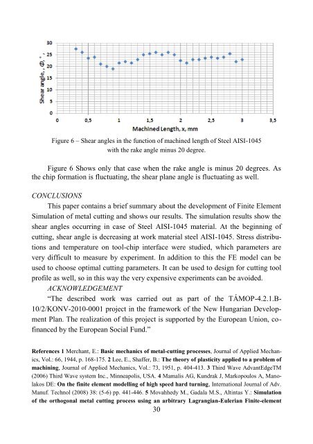
Figure 6 – Shear angles in the function of machined length of Steel AISI-1045 with the rake angle minus 20 degree. Figure 6 Shows only that case when the rake angle is minus 20 degrees. As the chip formation is fluctuating, the shear plane angle is fluctuating as well. CONCLUSIONS This paper contains a brief summary about the development of Finite Element Simulation of metal cutting and shows our results. The simulation results show the shear angles occurring in case of Steel AISI-1045 material. At the beginning of cutting, shear angle is decreasing at work material steel AISI-1045. Stress distributions and temperature on tool-chip interface were studied, which parameters are very difficult to measure by experiment. In addition to this the FE model can be used to choose optimal cutting parameters. It can be used to design for cutting tool profile as well, so in this way the very expensive experiments can be avoided. ACKNOWLEDGEMENT ―The described work was carried out as part of the TÁMOP-4.2.1.B- 10/2/KONV-2010-0001 project in the framework of the New Hungarian Development Plan. The realization of this project is supported by the European Union, cofinanced by the European Social Fund.‖ References 1 Merchant, E.: Basic mechanics of metal-cutting processes, Journal of Applied Mechanics, Vol.: 66, 1944, p. 168-175. 2 Lee, E., Shaffer, B.: The theory of plasticity applied to a problem of machining, Journal of Applied Mechanics, Vol.: 73, 1951, p. 404-413. 3 Third Wave AdvantEdgeTM (2006) Third Wave system Inc., Minneapolis, USA. 4 Mamalis AG, Kundrak J, Markopoulos A, Manolakos DE: On the finite element modelling of high speed hard turning, International Journal of Adv. Manuf. Technol (2008) 38: (5-6) pp. 441-446. 5 Movahhedy M., Gadala M.S., Altintas Y.: Simulation of the orthogonal metal cutting process using an arbitrary Lagrangian-Eulerian Finite-element 30
method, Journal of Materials Processing Technology 103 (2000) 267-275, 6 Pantalé O., Bacaria J.-L., Dalverny O., Rakotomalala R., Caperaa S.: 2D and 3D numerical models of metal cutting with damage effects, Computational Methods Appl. Mech. Engineering 193 (2004) 4383–4399, 7 Grzesik W (2008) Advanced machining processes of metallic materials. Elsvier, London 8 Zorev, N. N.: Metal Cutting Mechanics, Oxford, UK: Pergamon Press. 1966 9 Binglin Li, Xuelin Wang, Yujin Hu, Chenggang Li: Analytical prediction of cutting forces in orthogonal cutting using unequal division shear-zone model, Int J Adv Manuf Technol (2011) 54:431–443 10 Astakhov VP, Osman MOM, Hayajneh MT (2001) Re-evaluation of the basic mechanics of orthogonal metal cutting: velocity diagram, virtual work equation, and upper bound theorem. Int J Mach Tools Manuf 41:393–418 11 Ramesh MV., Chan KC, Lee WB, Cheung CF: Finite-element analysis of diamond turning of aluminium matrix composites, Composites Science and Technology 61 (2001) pp.: 1449–1456 12 Özel, T., Zeren, E. Numerical modelling of meso-scale finish machining with finite edge radius tools, International Journal of Machining and Machinability of Materials, Vol. 2, No. 3, 2007, Publisher’s website: www.inderscience.com, ISSN (Print) 1748-5711, ISSN (Online) 1748-572X, pp.: 451-477 13 Astakhov, V. P.: Metal Cutting Mechanics, Boca Raton, FL, USA: CRC Press. 1999 14 Johnson, G., Cook, W.: A constitutive model and data for metals subjected to large strains, high strain rates and high temperatures, 7th International Symposyum on Ballistics, 1983, pp.: 541-547 15 Jaspers, S.P.F.C., Dautzenberg, J.H.: Material behavior in conditions similar to metal cutting: flow stress in the primary shear zone, Journal of Materials Processing Technology, Vol. 122, 2002, pp.322–330. 16 Dirikolu, M.H., Childs, T.H.C., Maekawa, K.: Finite element simulation of chip flow in metal machining, International Journal of Mechanical Sciences, Vol. 43, 2001, pp.2699–2713. 17 Özel, T., Altan, M. T.: Determination of workpiece flow stress and friction at thechip–tool contact for high-speed cutting, International Journal of Machine Tools & Manufacture 40, 2000, pp.: 133–152. 18 Sartkulvanich, P., Altan, T., Göcmen, A.: Effects of Flow stress and Friction Models in Finite Element Simulation of Orthogonal Cutting – a Sensivitivity Analysis, Machine Science and Technology, (2005) 9, pp.: 1–26. 19 Čep, R., Neslušan, M.; Barišič, B.: Chip Formation Analysis during Hard Turning. Strojarstvo, 2008, vol 50, No. 6, pp.: 337 – 345, ISSN 0562 – 1887. 20 Lee, E., Shaffer, B.: The theory of plasticity applied to a problem of machining, Journal of Applied Mechanics, Vol.: 73, 1951, p. 404- 413. 21 Iwata, K., Osakada, K., Terasaka, Y.: Process modeling of orthogonal cutting by the rigidplastic finite element method, ASME Journal of Engineering for Industry 106, 1984, pp.: 132–138. 22 Özel, T., Altan, M. T.: Determination of workpiece flow stress and friction at thechip–tool contact for high-speed cutting, International Journal of Machine Tools & Manufacture 40, 2000, pp.: 133–152. 23 Shaw, M. C.: Metal Cutting Principles, Oxford University Press, Oxford, 1984. 24 Ambati, R.: Simulation and Analysis of Orthogonal Cutting and Drilling Processes using LS-DYNA, Master of Science Thesis at University of Stuttgart, University of Stuttgart, Germany, December 2007-June 2008, p.: 71 5 Nyiro, J.: Results of analysis of cutting, FMTU, Cluj Napoca, Romania, March 22-23, 2002, pp.: 109-112 Поступила в редколлегию 15.04.2011 31
- Page 1 and 2: МИНИСТЕРСТВО ОБРАЗ
- Page 3 and 4: УДК: 62.799:628.87 В.С. Ант
- Page 5 and 6: за рахунок меншої п
- Page 7 and 8: q c u 0 , un uout , 0 , n n n
- Page 9 and 10: Практична реалізац
- Page 11 and 12: клас чистоти 6 ISO. В
- Page 13 and 14: Рисунок 3 - Електрон
- Page 15 and 16: УДК 621.9 Е. А. Бабенко
- Page 17 and 18: верждены параметры
- Page 19 and 20: уровне С в материал
- Page 21 and 22: Рисунок 5 - Топограф
- Page 23 and 24: For simulation of cutting process,
- Page 25 and 26: the damping forces are T f Di Ni
- Page 27 and 28: element simulation of metal cutting
- Page 29: meshing the model. This can be used
- Page 33 and 34: прямоугольная плас
- Page 35 and 36: силе P . На рис. 2 при
- Page 37 and 38: Циклом фрезеровани
- Page 39 and 40: грубее токарная об
- Page 41 and 42: σ, МПа смещен в обла
- Page 43 and 44: УДК 621.923 А. И. Грабче
- Page 45 and 46: многом определяет
- Page 47 and 48: Поскольку критичес
- Page 49 and 50: В связи с эти была в
- Page 51 and 52: MB1 100%; Vк = 20 м/с; Sпр = 1
- Page 53 and 54: стабильным микрора
- Page 55 and 56: Список использован
- Page 57 and 58: нению с цементацие
- Page 59 and 60: Как можно судить по
- Page 61 and 62: зии углерода с обра
- Page 63 and 64: в зону резания (или
- Page 65 and 66: y обработки Q с тече
- Page 67 and 68: раняются при шлифо
- Page 69 and 70: ностей РЧ, требующи
- Page 71 and 72: Тогда A - матрица ра
- Page 73 and 74: бражения на экране
- Page 75 and 76: Рисунок 5 - Зависимо
- Page 77 and 78: 01-100%, а в качестве С
- Page 79 and 80: Шероховатость (Ra), м
- Page 81 and 82:
- рассмотреть возмо
- Page 83 and 84:
где FPz - радиальная
- Page 85 and 86:
Рисунок - Схема сво
- Page 87 and 88:
заготовки в положи
- Page 89 and 90:
V W 0,5 D cos , (21) mux u u m V
- Page 91 and 92:
Результаты аналити
- Page 93 and 94:
ляются определяющи
- Page 95 and 96:
N Z min , максимальные
- Page 97 and 98:
V T XYZ N Face VT i , (11) где
- Page 99 and 100:
Поверхностные Площ
- Page 101 and 102:
дель Вселенной», 2005
- Page 103 and 104:
Режущие инструмент
- Page 105 and 106:
зивная обработка п
- Page 107 and 108:
термином подразуме
- Page 109 and 110:
Результатом интенс
- Page 111 and 112:
проводности алмаза
- Page 113 and 114:
40 с., по стойкости и
- Page 115 and 116:
2.1. Minimum of vibration and mecha
- Page 117 and 118:
On base of the calculations and the
- Page 119 and 120:
namics is also ggod, yellow and cre
- Page 121 and 122:
УДК 621.9.01:519.6 В.А. Зал
- Page 123 and 124:
Таблица 1 - Сравнени
- Page 125 and 126:
ПРИРОСТ ПРОИЗВОДИТ
- Page 127 and 128:
Таблица 3 - Сведения
- Page 129 and 130:
а б а в , с г , с д е Ри
- Page 131 and 132:
УДК 621.623 В.И. Кальче
- Page 133 and 134:
При этом линия конт
- Page 135 and 136:
на профиле шлифова
- Page 137 and 138:
3 2 1 Рисунок 9 - Влиян
- Page 139 and 140:
Как видно из рисунк
- Page 141 and 142:
UDK 621.9 J. Kundrák, Miskolc, Hun
- Page 143 and 144:
Figure 1 - Processes, auxiliary mat
- Page 145 and 146:
CL quantity CL quantity The data of
- Page 147 and 148:
CL quantity CL quantity This time t
- Page 149 and 150:
UDK 621.9 J. Kundrak, I. Deszpoth,
- Page 151 and 152:
Table 1 - Technological data of cut
- Page 153 and 154:
Operation time, t op [min] 0.0 0.5
- Page 155 and 156:
Material removal rate, Q wp, op [mm
- Page 157 and 158:
UDK 621.9 J. Kundrak, G. Szabo, Mis
- Page 159 and 160:
the material, the high compressive
- Page 161 and 162:
4. RESULTS OF THE FEM- SIMULATION T
- Page 163 and 164:
Maramhao C.: A Study of Plastic Str
- Page 165 and 166:
могут привести к по
- Page 167 and 168:
АКТП позволяют пре
- Page 169 and 170:
где A - текущее АКТП
- Page 171 and 172:
мм 3 /хв. (швидкість
- Page 173 and 174:
зносостійкості кру
- Page 175 and 176:
шорсткості оброблю
- Page 177 and 178:
mean roughness R a , μm 2. QUALITY
- Page 179 and 180:
waviness W t , μm 200 250 300 200
- Page 181 and 182:
УДК 621.923 П. Г. Матюха
- Page 183 and 184:
ва, Вт/м·град; а - ко
- Page 185 and 186:
зерна (d=h), мм; к - ко
- Page 187 and 188:
- соотношение норма
- Page 189 and 190:
Продолжение табл.1 1
- Page 191 and 192:
УДК 621. 22 С. Р. Мемето
- Page 193 and 194:
Измерение силовых
- Page 195 and 196:
ность применения в
- Page 197 and 198:
АО растворенного в
- Page 199 and 200:
Повышение вязкости
- Page 201 and 202:
вязкость исходных
- Page 203 and 204:
4 этап. Изучение мно
- Page 205 and 206:
напряженность труд
- Page 207 and 208:
является кривая t H
- Page 209 and 210:
УДК 621.9.015 Н.В. Новик
- Page 211 and 212:
большие сжимающие
- Page 213 and 214:
Рисунок 3 - Схема об
- Page 215 and 216:
a EC . (5) l cos arctg a Стор
- Page 217 and 218:
вится справедливым
- Page 219 and 220:
UDK 621.9 Z. Pаlmai, Miskolc, Hung
- Page 221 and 222:
Figure 1 - The geometry of flank we
- Page 223 and 224:
We chose f=0.25mm/rev, a=2.5mm and
- Page 225 and 226:
Figure 6 - Wear curve in vibrating
- Page 227 and 228:
маз. Хотя графит и а
- Page 229 and 230:
алмаза, толщина кот
- Page 231 and 232:
Установлено, что то
- Page 233 and 234:
Рисунок 7 - Мероприя
- Page 235 and 236:
Выводы и перспекти
- Page 237 and 238:
Рассмотрим особенн
- Page 239 and 240:
( )(1 ) ( ) 1 exp P P
- Page 241 and 242:
УДК 621.91 M. Rybicki, PhD. Eng.
- Page 243 and 244:
are much larger for the conditions
- Page 245 and 246:
a e 0,3mm a e 1,8mm a e 2,2mm feed
- Page 247 and 248:
л/год, страны СНГ (д
- Page 249 and 250:
дальность струи. [4].
- Page 251 and 252:
УДК 621.923 Р.М. Стрель
- Page 253 and 254:
Рисунок 1 - Микрофот
- Page 255 and 256:
а Рисунок 3 - Профил
- Page 257 and 258:
ρ=12 мкм ρ=12 мкм ×100 а
- Page 259 and 260:
UDK 621.921 R.S. Turmanidze Prof.,
- Page 261 and 262:
In Fig. 1a is shown the LPG scheme
- Page 263 and 264:
For elaboration of the theoretical
- Page 265 and 266:
Where γ γ vB vK B v o(R KA -2rш
- Page 267 and 268:
physical-mechanical properties of t
- Page 269 and 270:
матеріалів кругами
- Page 271 and 272:
України, є членом р
- Page 273 and 274:
техническом универ
- Page 275 and 276:
ского биографическ
- Page 277 and 278:
Добровольский А.В.,
- Page 279 and 280:
279