DA09 Differential Pressure Gauge Schematic Diagram - Fischer
DA09 Differential Pressure Gauge Schematic Diagram - Fischer
DA09 Differential Pressure Gauge Schematic Diagram - Fischer

Create successful ePaper yourself
Turn your PDF publications into a flip-book with our unique Google optimized e-Paper software.
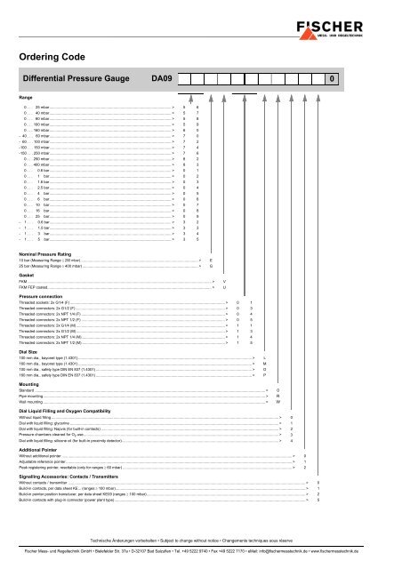
Ordering Code<br />
<strong>Differential</strong> <strong>Pressure</strong> <strong>Gauge</strong> <strong>DA09</strong><br />
0<br />
Range<br />
0 . . . 25 mbar...................................................................................................................... > 5 6<br />
0 . . . 40 mbar...................................................................................................................... > 5 7<br />
0 . . . 60 mbar...................................................................................................................... > 5 8<br />
0 . . . 100 mbar...................................................................................................................... > 5 9<br />
0 . . . 160 mbar...................................................................................................................... > 6 0<br />
- 40 . . . 60 mbar...................................................................................................................... > 7 0<br />
- 60 . . . 100 mbar...................................................................................................................... > 7 2<br />
-100 . . . 150 mbar...................................................................................................................... > 7 4<br />
-150 . . . 250 mbar...................................................................................................................... > 7 6<br />
0 . . . 250 mbar...................................................................................................................... > 8 2<br />
0 . . . 400 mbar...................................................................................................................... > 8 3<br />
0 . . . 0.6 bar...................................................................................................................... > 0 1<br />
0 . . . 1 bar...................................................................................................................... > 0 2<br />
0 . . . 1.6 bar...................................................................................................................... > 0 3<br />
0 . . . 2.5 bar...................................................................................................................... > 0 4<br />
0 . . . 4 bar...................................................................................................................... > 0 5<br />
0 . . . 6 bar...................................................................................................................... > 0 6<br />
0 . . . 10 bar...................................................................................................................... > 0 7<br />
0 . . . 16 bar...................................................................................................................... > 0 8<br />
0 . . . 25 bar...................................................................................................................... > 0 9<br />
- 1 . . . 0.6 bar...................................................................................................................... > 3 2<br />
- 1 . . . 1.5 bar...................................................................................................................... > 3 3<br />
- 1 . . . 3 bar...................................................................................................................... > 3 4<br />
- 1 . . . 5 bar...................................................................................................................... > 3 5<br />
Nominal <strong>Pressure</strong> Rating<br />
10 bar (Measuring Range ≤ 250 mbar).................................................................................................................. > E<br />
25 bar (Measuring Range ≥ 400 mbar) ................................................................................................................ > G<br />
Gasket<br />
FKM .................................................................................................................................................................................. ><br />
FKM FEP coated............................................................................................................................................................... ><br />
V<br />
U<br />
<strong>Pressure</strong> connection<br />
Threaded sockets: 2x G1/4 (F) ...................................................................................................................................................... > 0 1<br />
Threaded connectors: 2x G1/2 (F)................................................................................................................................................. > 0 3<br />
Threaded connectors: 2x NPT 1/4 (F) ........................................................................................................................................... > 0 4<br />
Threaded connectors: 2x NPT 1/2 (F) ........................................................................................................................................... > 0 5<br />
Threaded connectors: 2x G1/4 (M)................................................................................................................................................ > 1 1<br />
Threaded connectors: 2x G1/2 (M)................................................................................................................................................ > 1 3<br />
Threaded connectors: 2x NPT 1/4 (M)........................................................................................................................................... > 1 4<br />
Threaded connectors: 2x NPT 1/2 (M)........................................................................................................................................... > 1 5<br />
Dial Size<br />
100 mm dia., bayonet type (1.4301) ........................................................................................................................................................................ > L<br />
160 mm dia., bayonet type (1.4301) ........................................................................................................................................................................ > M<br />
100 mm dia., safety type DIN EN 837 (1.4301) ....................................................................................................................................................... > O<br />
160 mm dia., safety type DIN EN 837 (1.4301) ....................................................................................................................................................... > P<br />
Mounting<br />
Standard ............................................................................................................................................................................................................................... > 0<br />
Pipe mounting....................................................................................................................................................................................................................... > R<br />
Wall mounting ....................................................................................................................................................................................................................... > W<br />
Dial Liquid Filling and Oxygen Compatibility<br />
Without liquid filling ............................................................................................................................................................................................................................ > 0<br />
Dial with liquid filling: glycerine .......................................................................................................................................................................................................... > 1<br />
Dial with liquid filling: Napvis (for built-in contacts) ............................................................................................................................................................................ > 2<br />
<strong>Pressure</strong> chambers cleaned for O 2 use............................................................................................................................................................................................. > 3<br />
Dial with liquid filling: silicone oil (for built-in proximity detector)........................................................................................................................................................ > 4<br />
Additional Pointer<br />
Without additional pointer ............................................................................................................................................................................................................................... > 0<br />
Adjustable reference pointer ........................................................................................................................................................................................................................... > 1<br />
Peak registering pointer, resettable (only for ranges ≥ 60 mbar) .................................................................................................................................................................... > 2<br />
Signalling Accessories: Contacts / Transmitters<br />
Without contacts / transmitter ...................................................................................................................................................................................................................................... > 0<br />
Build-in contacts, per data sheet KE... (ranges ≥ 100 mbar)........................................................................................................................................................................................ > 1<br />
Build-in pointer position transducer, per data sheet KE09 (ranges ≥ 100 mbar).......................................................................................................................................................... > 2<br />
Build-in contacts with plug-in connector (power plant type)......................................................................................................................................................................................... > 5<br />
Technische Änderungen vorbehalten • Subject to change without notice • Changements techniques sous réserve<br />
<strong>Fischer</strong> Mess- und Regeltechnik GmbH • Bielefelder Str. 37a • D-32107 Bad Salzuflen • Tel. +49 5222 9740 • Fax +49 5222 7170 • eMail: info@fischermesstechnik.de • www.fischermesstechnik.de