DS21 Differential Pressure Switch
DS21 Differential Pressure Switch
DS21 Differential Pressure Switch

Create successful ePaper yourself
Turn your PDF publications into a flip-book with our unique Google optimized e-Paper software.
13.6.07 DB_GB_<strong>DS21</strong>.fm<br />
<strong>DS21</strong> <strong>Differential</strong> <strong>Pressure</strong> <strong>Switch</strong><br />
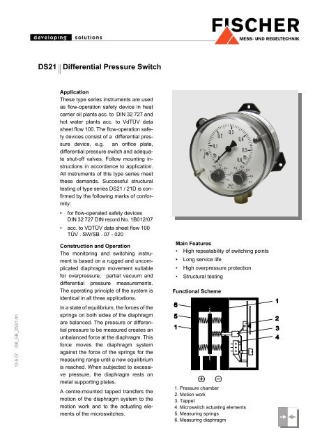
Application<br />
These type series instruments are used<br />
as flow-operation safety device in heat<br />
carrier oil plants acc. to DIN 32 727 and<br />
hot water plants acc. to VdTÜV data<br />
sheet flow 100. The flow-operation safety<br />
devices consist of a differential pressure<br />
device, e.g. an orifice plate,<br />
differential pressure switch and adequate<br />
shut-off valves. Follow mounting instructions<br />
in accordance to application.<br />
All instruments of this type series meet<br />
these demands. Successful structural<br />
testing of type series <strong>DS21</strong> / 21D is confirmed<br />
by the following marks of conformity:<br />
• for flow-operated safety devices<br />
DIN 32 727 DIN record No. 1B012/07<br />
• acc. to VDTÜV data sheet flow 100<br />
TÜV . SW/SB . 07 - 020<br />
Construction and Operation<br />
The monitoring and switching instrument<br />
is based on a rugged and uncomplicated<br />
diaphragm movement suitable<br />
for overpressure, partial vacuum and<br />
differential pressure measurements.<br />
The operating principle of the system is<br />
identical in all three applications.<br />
In a state of equilibrium, the forces of the<br />
springs on both sides of the diaphragm<br />
are balanced. The pressure or differential<br />
pressure to be measured creates an<br />
unbalanced force at the diaphragm. This<br />
force moves the diaphragm system<br />
against the force of the springs for the<br />
measuring range until a new equilibrium<br />
is reached. When subjected to excessive<br />
pressure, the diaphragm rests on<br />
metal supporting plates.<br />
A centre-mounted tapped transfers the<br />
motion of the diaphragm system to the<br />
motion work and to the actuating elements<br />
of the microswitches.<br />
Main Features<br />
• High repeatability of switching points<br />
• Long service life<br />
• High overpressure protection<br />
• Structural testing<br />
Functional Scheme<br />
1. <strong>Pressure</strong> chamber<br />
2. Motion work<br />
3. Tappet<br />
4. Microswitch actuating elements<br />
5. Measuring springs<br />
6. Measuring diaphragm
Specifications<br />
General<br />
Measuring range 0... 250 mbar up to 0... 6 bar (see ordering code)<br />
Nominal pressure 25 bar<br />
Max. static operating pressure Acc. to measuring range (see ordering code)<br />
Max. pressure load One-sided overpressure protected up to nominal pressure<br />
on (+) - and (−) side of diaphragm, partial vacuum protected<br />
Perm. ambient temperature -10... +70°C<br />
Perm. medium temperature 70°C<br />
Protection class IP 54 acc. to DIN EN 60529<br />
Mounting position Vertical<br />
Measuring accuracy ± 2.5% FS<br />
Zero adjustment Located in the dial<br />
<strong>Switch</strong>ing Elements<br />
Contact output 1 or 2 microswitches, 1-channel change-over contacts<br />
Adjustment of switching points External adjustment by standard value scales<br />
smallest adjustable value: approx. 5% FS<br />
<strong>Switch</strong>ing hysteresis Approx. 2.5% FS<br />
Load data / contacts U~ max. = 250 V AC, I max. = 5 A, P max. = 250 VA<br />
U= max. = 30 V DC, I max. = 0.4 A, P max. = 10 W<br />
Electrical Connection Numbered cable, prewired terminal box, 7-channel plug<br />
<strong>Pressure</strong> Connection Thread G1/4 female, cutting ring connection for 6, 8, 10,12 mm ∅ tube<br />
of brass, zinced steel or chrome nickel steel<br />
connection shank G1/4 male DIN EN 837<br />
Measuring System Diaphragm measuring system, diaphragm of reinforced Viton ®<br />
Materials<br />
<strong>Pressure</strong> chamber Aluminium GkAlSi10(Mg), varnished black<br />
Aluminium GkAlSi10(Mg) HART-COAT ® surface protection<br />
Chrome nickel steel 1.4305<br />
Measuring diaphragm Diaphragm measuring system and gaskets of Viton ®<br />
Materials: medium Stainless steel 1.4310, 1.4305<br />
Materials: housing Macrolon<br />
Weight <strong>Pressure</strong> chamber of Aluminium = 1.2 kg, pressure chamber of 1.4305 = 3.5 kg<br />
Mounting Wallmounting - 3 fastening elements<br />
Panel mounting - panel mounting kit DZ11 ø132 mm<br />
Pipe mounting, pressure connections � (+), (−) symbols<br />
- by screwed-in cutting ring or clamping ring connection<br />
- by screwed-in connection shank acc. to DIN EN 837 for nipple fitting acc. to<br />
DIN 16284
Dimensions (all units in mm unless otherwise stated)<br />
M16x1.5<br />
plastic cable<br />
gland<br />
M20x1.5 cable gland<br />
Cutting ring<br />
connection<br />
Prewired terminal box<br />
or 7-pin connector<br />
21D - <strong>DS21</strong><br />
Wallmounting<br />
(standard)<br />
Connections G¼ female<br />
Variants of Electrical Connection Variants of Process Connection
Ordering Code<br />
<strong>Differential</strong> <strong>Pressure</strong><br />
<strong>Switch</strong> <strong>DS21</strong><br />
Range Max. static pressure<br />
# # # 0<br />
�21D<br />
0 . . . 400 mbar 6 bar ............................................ > 8 3 ................................................................> 156<br />
0 . . . 0.6 bar 10 bar ............................................ > 0 1 ................................................................> 015<br />
0 . . . 1 bar 16 bar ............................................ > 0 2 ................................................................> 025<br />
0 . . . 1.6 bar 16 bar ............................................ > 0 3 ................................................................> 035<br />
0 . . . 2.5 bar 16 bar ............................................ > 0 4 ................................................................> 045<br />
0 . . . 4 bar 16 bar ............................................ > 0 5 ................................................................> 055<br />
0 . . . 6 bar 16 bar ............................................ > 0 6 ................................................................> 065<br />
Application<br />
Thermal oil DIN 32727..................................................................................... > T ........................................................................................> T<br />
Hot water / Flow 100........................................................................................ > W ........................................................................................> W<br />
<strong>Pressure</strong> Chamber<br />
Aluminium ............................................................................................................... > A ................................................................................> A<br />
Aluminium HART COAT ® ....................................................................................... > D ................................................................................> D<br />
Chrome-nickel-steel 1.4305.................................................................................... > W ................................................................................> V<br />
<strong>Pressure</strong> Connection<br />
Female thread G1/4.........................................................................................................> 0 1 ................................................................................................> R<br />
Cutting ring fitting of steel for 6 mm tube .......................................................................> 2 0 ................................................................................................> 6S<br />
Cutting ring fitting of steel for 8 mm tube .......................................................................> 2 1 ................................................................................................> 8S<br />
Cutting ring fitting of steel for 10 mm tube .......................................................................> 2 2 ................................................................................................> 10S<br />
Cutting ring fitting of steel for 12 mm tube .......................................................................> 2 3 ................................................................................................> 12S<br />
Cutting ring fitting of 1.4571 for 6 mm tube....................................................................> 2 4 ................................................................................................> 6V<br />
Cutting ring fitting of 1.4571 for 8 mm tube....................................................................> 2 5 ................................................................................................> 8V<br />
Cutting ring fitting of 1.4571 for 10 mm tube....................................................................> 2 6 ................................................................................................> 10V<br />
Cutting ring fitting of 1.4571 for 12 mm tube....................................................................> 2 7 ................................................................................................> 12V<br />
<strong>Switch</strong>ing Elements<br />
1 adjustable microswitch...................................................................................................................> A ........................................................................> K1<br />
2 adjustable microswitches...............................................................................................................> B ........................................................................> K2<br />
Electrical Connection<br />
Prewired terminal box ............................................................................................................................. > K ........................................................................................................> K<br />
GGL approved model, 3 m supply cable H07 RNF ................................................................................ > Z ........................................................................................................> Z<br />
Technische Änderungen vorbehalten • Subject to change without notice • Changements techniques sous réserve<br />
Fischer Mess- und Regeltechnik GmbH • Bielefelder Str. 37a • D-32107 Bad Salzuflen • Tel. +49 5222 9740 • Fax +49 5222 7170 • eMail: info@fischermesstechnik.de • www.fischermesstechnik.de