NC56 Capacitive Level Sensor - Fischer
NC56 Capacitive Level Sensor - Fischer
NC56 Capacitive Level Sensor - Fischer

Create successful ePaper yourself
Turn your PDF publications into a flip-book with our unique Google optimized e-Paper software.
<strong>NC56</strong><br />
<strong>Capacitive</strong> <strong>Level</strong> <strong>Sensor</strong><br />
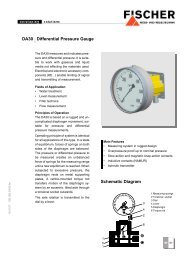
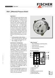
The Model <strong>NC56</strong> <strong>Capacitive</strong> <strong>Level</strong> <strong>Sensor</strong><br />
can be used for level measurement<br />
of<br />
• Clean water<br />
• Waste water and sewage<br />
• Diesel fuel<br />
• Fire suppression foam<br />
The <strong>NC56</strong> can be applied to plastic or<br />
metal tanks, and configured for measuring<br />
level in ranges from 400 to 2000<br />
mm.<br />
24.1.08 DB_GB_<strong>NC56</strong>.fm<br />
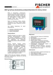
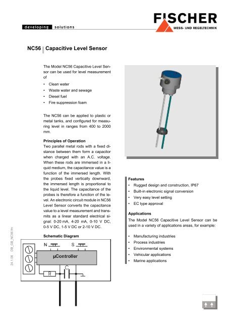
Principles of Operation<br />
Two parallel metal rods with a fixed distance<br />
between them form a capacitor<br />
when charged with an A.C. voltage.<br />
When these rods are immersed in a liquid<br />
medium, the capacitance value is a<br />
function of the immersed length. With<br />
the probes fixed vertically downward,<br />
the immersed length is proportional to<br />
the liquid level. The capacitance of the<br />
probes is therefore a function of the level.<br />
An electronic circuit module in <strong>NC56</strong><br />
<strong>Level</strong> <strong>Sensor</strong> converts the capacitance<br />
value to a level measurement and transmits<br />
as a linear standard electrical signal:<br />
0-20 mA, 4-20 mA, 0-10 V DC,<br />
0-5 V DC, 1-5 V DC or 2-10 V DC.<br />
Schematic Diagram<br />
Features<br />
• Rugged design and construction, IP67<br />
• Built-in electronic signal conversion<br />
• Very easy level setting<br />
• EC type approval<br />
Applications<br />
The Model <strong>NC56</strong> <strong>Capacitive</strong> <strong>Level</strong> <strong>Sensor</strong> can be<br />
used in a variety of applications areas, for example:<br />
• Manufacturing industries<br />
• Process industries<br />
• Environmental systems<br />
• Vehicular applications<br />
• Marine applications
Specifications<br />
General<br />
Sensing technique<br />
<strong>Level</strong> measuring range<br />
Operating pressure<br />
Temperature<br />
Number of electrodes<br />
Process connection<br />
Degree of protection<br />
Capacitance sensing<br />
400 - 2000 mm (other ranges available against special order)<br />
10 bar, max.<br />
Max. 80°C (ambient and media)<br />
2 (3 for diesel applications)<br />
Threaded G1¼" (M). With protective tube: G 2" (M)<br />
IP67<br />
Connection Diagram<br />
Electrical<br />
Operating voltage<br />
Supply current (without<br />
signal)<br />
Output signal<br />
Output load impedance<br />
Electrical Connection<br />
9 - 32 V DC<br />
approx. 30 mA<br />
0 - 20 mA<br />
(U B - 9 V) / 20mA<br />
9 - 32 V DC<br />
approx. 30 mA<br />
4 - 20 mA<br />
(U B - 9 V) / 20mA<br />
U B = Operating voltage<br />
12 - 32 V DC<br />
approx. 30 mA<br />
0 - 10 V DC<br />
> 5 k Ω<br />
Male M12 type round shell connector<br />
12 - 32 V DC<br />
approx. 30 mA<br />
0/1 - 5 V DC<br />
> 5 k Ω<br />
12 - 32 V DC<br />
approx. 30 mA<br />
2 - 10 V DC<br />
> 5 k Ω<br />
Materials<br />
Housing<br />
Media: contact<br />
Approval<br />
Plastic<br />
Stainless steel 1.4404, ECTFE, shrinking plastic tube (polyolefine)<br />
EC type-approval acc. to 72/245/EEC, 95/54/EC<br />
Type-approval No. e13*72/245*95/54*2182*00<br />
Installation<br />
The <strong>NC56</strong> <strong>Capacitive</strong> <strong>Level</strong> <strong>Sensor</strong> is installed vertically downward at the top of the<br />
vessel in which liquid level is to be measured. It is fitted into a G1¼-F threaded socket,<br />
located as close as possible to the center of the tank. The lower ends of the rods must<br />
be at least 10 mm above the tank bottom to avoid contact with any sludge that may be<br />
present. The electrode rods can be cut at site to a shorter length, if required, but must<br />
be of equal length.<br />
Commissioning and <strong>Level</strong> Setting<br />
The <strong>NC56</strong> <strong>Capacitive</strong> <strong>Level</strong> <strong>Sensor</strong> can be put into operation after it is installed.<br />
Detailed information regarding this is available in the Instruction Manual.<br />
<strong>Level</strong> setting is done in two steps. First, the liquid in the tank is brought to the lowest<br />
operating level. The minimum level is set simply by pressing the "Min" button on the<br />
infrared remote control unit. The LED lamp on the top of the instrument starts blinking<br />
faster, then stays steadily on, indicating that the zero level is registered. The button is<br />
then released. The tank is then filled up to its highest operating level. The "Max" button<br />
on the infrared remote control unit is pressed as before, until the instrument's LED is<br />
continuously lit. The <strong>NC56</strong> registers the maximum level and the level setting procedure<br />
is complete. The minimum or maximum limit level settings can be altered at any time,<br />
whenever the need arises, using the same procedure. If only one of limit setting needs<br />
to be changed, only one of two level setting buttons is used, after the liquid level in the<br />
tank is adjusted accordingly.<br />
For a downward characteristic (empty tank = high signal and filled tank = low<br />
signal) register the value for MAX with empty tank and the value for MIN with<br />
filled tank.<br />
Accessories<br />
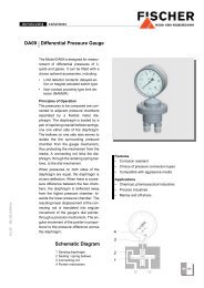
Infrared remote control unit model EU04.<br />
1. Infrared remote control<br />
2. Button “Min“<br />
3. Button “Max“<br />
4. LED lamp<br />
5. Infrared receiver
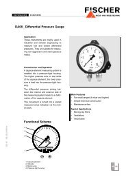
Dimensions (all units in mm unless otherwise stated)<br />
Electrodes Configuration for Water /<br />
Waste Water<br />
Electrodes Configuration for Furnace Oil, Diesel<br />
M12 connection<br />
M12 connection<br />
every 500 mm<br />
every 500 mm<br />
Electrodes Configuration for Firefighting<br />
Foam / Sewage<br />
Protection Tube<br />
Octagon head<br />
cap screw SW77<br />
M12 connection<br />
(4,8)<br />
every 500 mm<br />
adjusted to electrode length
Ordering Code<br />
<strong>Capacitive</strong> <strong>Level</strong> <strong>Sensor</strong><br />
<strong>NC56</strong><br />
# # # #<br />
Function<br />
Water / waste water<br />
(1 electrode coated with shrinking plastic tube /<br />
1 uncoated electrode, stainless steel 1.4404)..................... > 2<br />
Diesel<br />
(3 uncoated electrodes, stainless steel 1.4404)................... > 3<br />
Sewage<br />
(1 electrode ECTFE coated /<br />
1 uncoated electrode, stainless steel 1.4404)..................... > 4<br />
Firefighting foam<br />
(1 electrode ECTFE coated /<br />
1 uncoated electrode, stainless steel 1.4404)..................... > 5<br />
Material Housing / Connection<br />
Plastic housing with G 1¼ " (M) for outside use ......................... ><br />
Plastic housing and protective tube with G 2" (M)<br />
for outside use ............................................................................ ><br />
Plastic housing and protective tube with G 2“ (M)<br />
and boreholes for suction trucks, for outside use<br />
only with function 4 (sewage).................................................. ><br />
O<br />
P<br />
G<br />
Electrode Length (from housing bottom)<br />
400 - 2000 mm (in 50 mm steps) ........................................................ ><br />
............................................................................................................ ><br />
............................................................................................................ ><br />
............................................................................................................ ><br />
............................................................................................................ ><br />
0<br />
2<br />
4<br />
0<br />
0<br />
0<br />
0<br />
0<br />
Signal Output<br />
0 - 20 mA linear, 3-wire (STANDARD) ........................................................................> A<br />
0 - 10 V DC linear, 3-wire (STANDARD) ........................................................................> C<br />
4 - 20 mA linear, 3-wire (STANDARD) ........................................................................> P<br />
0 - 5 V DC linear, 3-wire ...............................................................................................> U<br />
1 - 5 V DC linear, 3-wire ...............................................................................................> D<br />
2 - 10 V DC linear, 3-wire ...............................................................................................> Z<br />
Supply Voltage<br />
9 - 32 VDC (only for current output).........................................................................................> E<br />
12 - 32 VDC (only for voltage output) ........................................................................................> F<br />
Technische Änderungen vorbehalten • Subject to change without notice • Changements techniques sous réserve<br />
<strong>Fischer</strong> Mess- und Regeltechnik GmbH • Bielefelder Str. 37a • D-32107 Bad Salzuflen • Tel. +49 5222 9740 • Fax +49 5222 7170 • eMail: info@fischermesstechnik.de • www.fischermesstechnik.de