DA09 Differential Pressure Gauge Schematic Diagram - Fischer
DA09 Differential Pressure Gauge Schematic Diagram - Fischer
DA09 Differential Pressure Gauge Schematic Diagram - Fischer

You also want an ePaper? Increase the reach of your titles
YUMPU automatically turns print PDFs into web optimized ePapers that Google loves.
<strong>DA09</strong><br />
<strong>Differential</strong> <strong>Pressure</strong> <strong>Gauge</strong><br />
The Model <strong>DA09</strong> is designed for measurement<br />
of differential pressures of liquids<br />
and gases. It can be fitted with a<br />
choice optional accessories, including:<br />
• Limit detector contacts: delayed-action<br />
or magnet actuated switch type<br />
• Non-contact proximity type limit detector<br />
(NAMUR)<br />
10.3.08 DB_GB_<strong>DA09</strong>.fm<br />
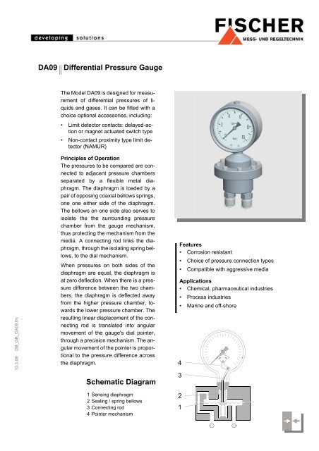
Principles of Operation<br />
The pressures to be compared are connected<br />
to adjacent pressure chambers<br />
separated by a flexible metal diaphragm.<br />
The diaphragm is loaded by a<br />
pair of opposing coaxial bellows springs,<br />
one one either side of the diaphragm.<br />
The bellows on one side also serves to<br />
isolate the the surrounding pressure<br />
chamber from the gauge mechanism,<br />
thus protecting the mechanism from the<br />
media. A connecting rod links the diaphragm,<br />
through the isolating spring bellows,<br />
to the dial mechanism.<br />
When pressures on both sides of the<br />
diaphragm are equal, the diaphragm is<br />
at zero deflection. When there is a pressure<br />
difference between the two chambers,<br />
the diaphragm is deflected away<br />
from the higher pressure chamber, towards<br />
the lower pressure chamber. The<br />
resulting linear displacement of the connecting<br />
rod is translated into angular<br />
movement of the gauge's dial pointer,<br />
through a precision mechanism. The angular<br />
movement of the pointer is proportional<br />
to the pressure difference across<br />
the diaphragm.<br />
<strong>Schematic</strong> <strong>Diagram</strong><br />
Features<br />
• Corrosion resistant<br />
• Choice of pressure connection types<br />
• Compatible with aggressive media<br />
Applications<br />
• Chemical, pharmaceutical industries<br />
• Process industries<br />
• Marine and off-shore<br />
4<br />
3<br />
1 Sensing diaphragm<br />
2 Sealing / spring bellows<br />
3 Connecting rod<br />
4 Pointer mechanism<br />
2<br />
1
Specifications<br />
Options and Accessories Materials General<br />
Ranges /<br />
max. statc pressure<br />
Accuracy<br />
Max. differential overpressure<br />
Indicator<br />
Operating temperature<br />
Temperature coefficient<br />
Zero adjustment<br />
Protection class<br />
<strong>Pressure</strong> connections<br />
<strong>Pressure</strong> chambers (media contact)<br />
Diaphragm (media contact)<br />
Bellows (media contact)<br />
Pointer mechanism<br />
Dial housing<br />
Dial window<br />
Dial scale and pointer<br />
O-ring seals<br />
Electrical accessories<br />
Liquid filling<br />
Reference pointer<br />
Peak registering pointer<br />
O2 - applications<br />
„degreased“<br />
0...25 mbar to 0...250 mbar / 10 bar<br />
400 mbar to 0...25 bar / 25 bar<br />
± 2.5% FS<br />
Either side: 10 x FS<br />
Circular dial type, 100mm or 160mm diameter,<br />
safety housing DIN EN 837 NG 100 o. NG 160<br />
Ambient: -20°C to +80°C<br />
Medium: +100°C, maximum<br />
Approx. 0.3% / 10K<br />
By screw on top of gauge housing, ±25% FS<br />
IP 54, per DIN EN 60529<br />
Threaded sockets 2x G¼ (F); plus other optional types (see Ordering Code)<br />
Stainless steel 1.4404 (AISI 316L)<br />
Ranges ≤ 400mbar: stainless steel 1.4571 (AISI 316Ti)<br />
Ranges ≥ 0.6 bar: DURATHERM ® (stainless steel)<br />
Stainless steel 1.4571<br />
Stainless steel 1.4301<br />
Stainless steel 1.4301<br />
Laminated safety glass<br />
Aluminium<br />
FPM (fluorocarbon elastomer)<br />
Limit signalling contacts: delayed action / magnet actuated switch type / non-contact<br />
proximity type limit detector.<br />
Pointer rotation transducer: capacitance type, with output signal proportional to the<br />
pointer position (uses deeper gauge housing: see Dimensions)<br />
For details of electrical accessories, see Data Sheet KE.<br />
Accessories applicable on ranges ≥ 100 mbar<br />
For operating conditions involving vibration, pressure fluctuations, and/or moisture<br />
condensation inside, the gauge can be supplied with glycerine filling.<br />
Instruments with build-in contacts will be filled with NAPVIS for better electrical<br />
isolation. In case of inductive contacts silicon oil will be used.<br />
Adjustable pointer for visual marking of limit / reference values<br />
Separate pointer without spring, friction holding: dragged by the measuring pointer as<br />
the measured value increases. Stays put when the measuring value recedes, thereby<br />
registering peak value. Manual re-setting (Range ≥ 60 mbar).<br />
According to German „BG-Chemie“ regulations all wetted parts will be degreased.<br />
(See ordering code 3 at item „Dial liquid filling“)<br />
Options (on request) Special dial scales, housing material: stainless steel 1.4571<br />
Accessories<br />
Blocking / equalising valves unit, models DZ 93/94: Three and four spindle types. For<br />
zero calibration, static pressure testing, and sealing pressure source when removing<br />
gauge for servicing. The fourth spindle in the model DZ 94 can be used to vent the<br />
pressure source.<br />
Mounting<br />
pipe fitting<br />
wall mounting<br />
pipe mounting<br />
On pressure connections<br />
With mounting plate<br />
With mounting plate and fastening bow<br />
<strong>Pressure</strong> connection by means of threaded cutting ring connectors or direct fitted<br />
pressure lines should be carried out with appropriate jointing compound.
Dimensions (all units in mm unless stated otherwise)<br />
(with built-in contacts)<br />
(with built-in contacts)<br />
(with built-in contacts)<br />
for ranges 0.4...25 bar<br />
Connector<br />
with M20x1.5<br />
cable gland<br />
Sealing surface<br />
Dial size D H A L L1<br />
NG100 ∅101 140 86 100 116<br />
NG160 ∅161 170 120 102 118<br />
Wall Mounting Option<br />
Pipe Mounting Option<br />
2’’-Pipe<br />
for ranges 25...250 mbar<br />
D<br />
L<br />
(with (mit eingebauten built-in contacts) Kontakten)<br />
55<br />
40<br />
A<br />
(with(mit built-in eingebauten contacts)<br />
Kontakten)<br />
Connector with<br />
M20x1.5<br />
Anschlussstecker<br />
M20x1,5 cable<br />
gland Verschraubung<br />
H<br />
D<br />
L1<br />
(with(mit built-in eingebauten contacts)<br />
Kontakten)<br />
70<br />
37<br />
Safety Option <strong>Gauge</strong> Sicherheitsgehäuse Housing Option<br />
15<br />
136<br />
G1/4<br />
37<br />
<strong>Pressure</strong> Dichtfläche connection surface<br />
11<br />
Dial size D H A L L1<br />
73<br />
NG100 ∅101 140 86 100 116<br />
NG160 ∅161 170 120 102 118<br />
74<br />
Wall Mounting Option<br />
73 114<br />
Pipe Mounting Option<br />
2’’-Pipe<br />
2"-Rohr<br />
Connections<br />
L<br />
L1<br />
center Zentrierzapfen bolt according<br />
DIN ähnlich EN 873-3 DIN EN with 837-3 G1/4<br />
and nur G bei 1/2 G1/4 onlyund G1/2<br />
outside threading<br />
G<br />
hex.<br />
Skt.SW<br />
wr.<br />
G size<br />
37<br />
L L1 SW<br />
G 1/4 25 12 19<br />
G 1/2 34 17 22<br />
L<br />
L1<br />
G<br />
inside threading<br />
G<br />
37<br />
L L1 SW<br />
G 1/2 26 19 27<br />
1/4-18 NPT 20 - 19<br />
hex. Skt.SW wrench size<br />
Option: Three spindle<br />
blocking valve DZ 93<br />
or<br />
Four spindle blocking<br />
valve DZ 94<br />
gasket<br />
vent<br />
HWS 22<br />
1/4-18 NPT 30 12 19<br />
1/2-14 NPT 26 - 27<br />
1/2-14 NPT 37 13 22
Ordering Code<br />
<strong>Differential</strong> <strong>Pressure</strong> <strong>Gauge</strong> <strong>DA09</strong><br />
0<br />
Range<br />
0 . . . 25 mbar...................................................................................................................... > 5 6<br />
0 . . . 40 mbar...................................................................................................................... > 5 7<br />
0 . . . 60 mbar...................................................................................................................... > 5 8<br />
0 . . . 100 mbar...................................................................................................................... > 5 9<br />
0 . . . 160 mbar...................................................................................................................... > 6 0<br />
- 40 . . . 60 mbar...................................................................................................................... > 7 0<br />
- 60 . . . 100 mbar...................................................................................................................... > 7 2<br />
-100 . . . 150 mbar...................................................................................................................... > 7 4<br />
-150 . . . 250 mbar...................................................................................................................... > 7 6<br />
0 . . . 250 mbar...................................................................................................................... > 8 2<br />
0 . . . 400 mbar...................................................................................................................... > 8 3<br />
0 . . . 0.6 bar...................................................................................................................... > 0 1<br />
0 . . . 1 bar...................................................................................................................... > 0 2<br />
0 . . . 1.6 bar...................................................................................................................... > 0 3<br />
0 . . . 2.5 bar...................................................................................................................... > 0 4<br />
0 . . . 4 bar...................................................................................................................... > 0 5<br />
0 . . . 6 bar...................................................................................................................... > 0 6<br />
0 . . . 10 bar...................................................................................................................... > 0 7<br />
0 . . . 16 bar...................................................................................................................... > 0 8<br />
0 . . . 25 bar...................................................................................................................... > 0 9<br />
- 1 . . . 0.6 bar...................................................................................................................... > 3 2<br />
- 1 . . . 1.5 bar...................................................................................................................... > 3 3<br />
- 1 . . . 3 bar...................................................................................................................... > 3 4<br />
- 1 . . . 5 bar...................................................................................................................... > 3 5<br />
Nominal <strong>Pressure</strong> Rating<br />
10 bar (Measuring Range ≤ 250 mbar).................................................................................................................. > E<br />
25 bar (Measuring Range ≥ 400 mbar) ................................................................................................................ > G<br />
Gasket<br />
FKM .................................................................................................................................................................................. ><br />
FKM FEP coated............................................................................................................................................................... ><br />
V<br />
U<br />
<strong>Pressure</strong> connection<br />
Threaded sockets: 2x G1/4 (F) ...................................................................................................................................................... > 0 1<br />
Threaded connectors: 2x G1/2 (F)................................................................................................................................................. > 0 3<br />
Threaded connectors: 2x NPT 1/4 (F) ........................................................................................................................................... > 0 4<br />
Threaded connectors: 2x NPT 1/2 (F) ........................................................................................................................................... > 0 5<br />
Threaded connectors: 2x G1/4 (M)................................................................................................................................................ > 1 1<br />
Threaded connectors: 2x G1/2 (M)................................................................................................................................................ > 1 3<br />
Threaded connectors: 2x NPT 1/4 (M)........................................................................................................................................... > 1 4<br />
Threaded connectors: 2x NPT 1/2 (M)........................................................................................................................................... > 1 5<br />
Dial Size<br />
100 mm dia., bayonet type (1.4301) ........................................................................................................................................................................ > L<br />
160 mm dia., bayonet type (1.4301) ........................................................................................................................................................................ > M<br />
100 mm dia., safety type DIN EN 837 (1.4301) ....................................................................................................................................................... > O<br />
160 mm dia., safety type DIN EN 837 (1.4301) ....................................................................................................................................................... > P<br />
Mounting<br />
Standard ............................................................................................................................................................................................................................... > 0<br />
Pipe mounting....................................................................................................................................................................................................................... > R<br />
Wall mounting ....................................................................................................................................................................................................................... > W<br />
Dial Liquid Filling and Oxygen Compatibility<br />
Without liquid filling ............................................................................................................................................................................................................................ > 0<br />
Dial with liquid filling: glycerine .......................................................................................................................................................................................................... > 1<br />
Dial with liquid filling: Napvis (for built-in contacts) ............................................................................................................................................................................ > 2<br />
<strong>Pressure</strong> chambers cleaned for O 2 use............................................................................................................................................................................................. > 3<br />
Dial with liquid filling: silicone oil (for built-in proximity detector)........................................................................................................................................................ > 4<br />
Additional Pointer<br />
Without additional pointer ............................................................................................................................................................................................................................... > 0<br />
Adjustable reference pointer ........................................................................................................................................................................................................................... > 1<br />
Peak registering pointer, resettable (only for ranges ≥ 60 mbar) .................................................................................................................................................................... > 2<br />
Signalling Accessories: Contacts / Transmitters<br />
Without contacts / transmitter ...................................................................................................................................................................................................................................... > 0<br />
Build-in contacts, per data sheet KE... (ranges ≥ 100 mbar)........................................................................................................................................................................................ > 1<br />
Build-in pointer position transducer, per data sheet KE09 (ranges ≥ 100 mbar).......................................................................................................................................................... > 2<br />
Build-in contacts with plug-in connector (power plant type)......................................................................................................................................................................................... > 5<br />
Technische Änderungen vorbehalten • Subject to change without notice • Changements techniques sous réserve<br />
<strong>Fischer</strong> Mess- und Regeltechnik GmbH • Bielefelder Str. 37a • D-32107 Bad Salzuflen • Tel. +49 5222 9740 • Fax +49 5222 7170 • eMail: info@fischermesstechnik.de • www.fischermesstechnik.de