- Page 1 and 2: Features • High Performance, Low
- Page 3 and 4: ATtiny2313A/4313 1.1 Pin Descriptio
- Page 5 and 6: ATtiny2313A/4313 2. Overview The AT
- Page 7 and 8: ATtiny2313A/4313 3. About 3.1 Resou
- Page 9 and 10: ATtiny2313A/4313 Six of the 32 regi
- Page 11 and 12: ATtiny2313A/4313 4.4 General Purpos
- Page 13 and 14: ATtiny2313A/4313 Figure 4-4. The Pa
- Page 15 and 16: ATtiny2313A/4313 4.7.1 Interrupt Re
- Page 17 and 18: ATtiny2313A/4313 5.2 Data Memory (S
- Page 19 and 20: ATtiny2313A/4313 The EEPROM memory
- Page 21 and 22: ATtiny2313A/4313 • The supply vol
- Page 23 and 24: ATtiny2313A/4313 C Code Example uns
- Page 25 and 26: ATtiny2313A/4313 • Bit 0 - EERE:
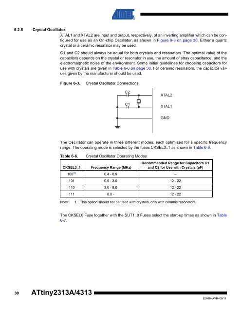
- Page 27 and 28: ATtiny2313A/4313 6.2 Clock Sources
- Page 29: ATtiny2313A/4313 Watchdog Timer and
- Page 33 and 34: ATtiny2313A/4313 the CLKPCE bit wit
- Page 35 and 36: ATtiny2313A/4313 parator Control an
- Page 37 and 38: ATtiny2313A/4313 7.5 Register Descr
- Page 39 and 40: ATtiny2313A/4313 8. System Control
- Page 41 and 42: ATtiny2313A/4313 8.2.2 External Res
- Page 43 and 44: ATtiny2313A/4313 The Watchdog Timer
- Page 45 and 46: ATtiny2313A/4313 8.5 Register Descr
- Page 47 and 48: ATtiny2313A/4313 • Bits 5, 2..0 -
- Page 49 and 50: ATtiny2313A/4313 The most typical a
- Page 51 and 52: ATtiny2313A/4313 9.3 Register Descr
- Page 53 and 54: ATtiny2313A/4313 9.3.3 GIFR - Gener
- Page 55 and 56: ATtiny2313A/4313 10. I/O-Ports All
- Page 57 and 58: ATtiny2313A/4313 10.1.2 Toggling th
- Page 59 and 60: ATtiny2313A/4313 important, it is r
- Page 61 and 62: ATtiny2313A/4313 Table 10-2 summari
- Page 63 and 64: ATtiny2313A/4313 Table 10-4 relates
- Page 65 and 66: ATtiny2313A/4313 (one)) to serve th
- Page 67 and 68: ATtiny2313A/4313 10.2.3 Alternate F
- Page 69 and 70: ATtiny2313A/4313 Table 10-10. Signa
- Page 71 and 72: ATtiny2313A/4313 11. 8-bit Timer/Co
- Page 73 and 74: ATtiny2313A/4313 Signal description
- Page 75 and 76: ATtiny2313A/4313 generation. Simila
- Page 77 and 78: ATtiny2313A/4313 Figure 11-5. CTC M
- Page 79 and 80: ATtiny2313A/4313 feature is similar
- Page 81 and 82:
ATtiny2313A/4313 Figure 11-9. Timer
- Page 83 and 84:
ATtiny2313A/4313 Table 11-4 shows t
- Page 85 and 86:
ATtiny2313A/4313 11.9.2 TCCR0B - Ti
- Page 87 and 88:
ATtiny2313A/4313 11.9.6 TIMSK - Tim
- Page 89 and 90:
ATtiny2313A/4313 12. 16-bit Timer/C
- Page 91 and 92:
ATtiny2313A/4313 12.2.3 Compatibili
- Page 93 and 94:
ATtiny2313A/4313 Figure 12-3. Input
- Page 95 and 96:
ATtiny2313A/4313 A special feature
- Page 97 and 98:
ATtiny2313A/4313 Figure 12-5. Compa
- Page 99 and 100:
ATtiny2313A/4313 Figure 12-6. CTC M
- Page 101 and 102:
ATtiny2313A/4313 The OCR1A Register
- Page 103 and 104:
ATtiny2313A/4313 implies that the l
- Page 105 and 106:
ATtiny2313A/4313 an inverted PWM ou
- Page 107 and 108:
ATtiny2313A/4313 Figure 12-13. Time
- Page 109 and 110:
ATtiny2313A/4313 The following code
- Page 111 and 112:
ATtiny2313A/4313 12.11 Register Des
- Page 113 and 114:
ATtiny2313A/4313 Table 12-5. Wavefo
- Page 115 and 116:
ATtiny2313A/4313 A FOC1A/FOC1B stro
- Page 117 and 118:
ATtiny2313A/4313 12.11.9 TIFR - Tim
- Page 119 and 120:
ATtiny2313A/4313 Enabling and disab
- Page 121 and 122:
ATtiny2313A/4313 The dashed boxes i
- Page 123 and 124:
ATtiny2313A/4313 Table 14-1. Operat
- Page 125 and 126:
ATtiny2313A/4313 St Start bit, alwa
- Page 127 and 128:
ATtiny2313A/4313 14.6.1 Sending Fra
- Page 129 and 130:
ATtiny2313A/4313 contains data to b
- Page 131 and 132:
ATtiny2313A/4313 change the state o
- Page 133 and 134:
ATtiny2313A/4313 Checker calculates
- Page 135 and 136:
ATtiny2313A/4313 Figure 14-7 shows
- Page 137 and 138:
ATtiny2313A/4313 the frame type bit
- Page 139 and 140:
ATtiny2313A/4313 • Bit 2 - UPE: U
- Page 141 and 142:
ATtiny2313A/4313 • Bit 3 - USBS:
- Page 143 and 144:
ATtiny2313A/4313 Table 14-10. Baud
- Page 145 and 146:
ATtiny2313A/4313 Table 14-12. Baud
- Page 147 and 148:
ATtiny2313A/4313 BAUD f OSC Baud ra
- Page 149 and 150:
ATtiny2313A/4313 baud rate is given
- Page 151 and 152:
ATtiny2313A/4313 Assembly Code Exam
- Page 153 and 154:
ATtiny2313A/4313 15.8 Register Desc
- Page 155 and 156:
ATtiny2313A/4313 • Bit 5:3 - Rese
- Page 157 and 158:
ATtiny2313A/4313 16.3 Functional De
- Page 159 and 160:
ATtiny2313A/4313 SPITransfer_loop:
- Page 161 and 162:
ATtiny2313A/4313 Figure 16-4. Two-w
- Page 163 and 164:
ATtiny2313A/4313 16.4 Alternative U
- Page 165 and 166:
ATtiny2313A/4313 Table 16-2 shows t
- Page 167 and 168:
ATtiny2313A/4313 16.5.4 USIBR - USI
- Page 169 and 170:
ATtiny2313A/4313 17.1.2 DIDR - Digi
- Page 171 and 172:
ATtiny2313A/4313 When designing a s
- Page 173 and 174:
ATtiny2313A/4313 19. Self-Programmi
- Page 175 and 176:
ATtiny2313A/4313 Although the least
- Page 177 and 178:
ATtiny2313A/4313 • Bit 5 - RSIG:
- Page 179 and 180:
ATtiny2313A/4313 20.2 Fuse Bits Fus
- Page 181 and 182:
ATtiny2313A/4313 2. See section “
- Page 183 and 184:
ATtiny2313A/4313 4. Wait three cloc
- Page 185 and 186:
ATtiny2313A/4313 Signals are descri
- Page 187 and 188:
ATtiny2313A/4313 21.2.2 Considerati
- Page 189 and 190:
ATtiny2313A/4313 Figure 21-2. Addre
- Page 191 and 192:
ATtiny2313A/4313 • B: Load Addres
- Page 193 and 194:
ATtiny2313A/4313 Figure 21-6. Mappi
- Page 195 and 196:
ATtiny2313A/4313 21.3.1 Pin Mapping
- Page 197 and 198:
ATtiny2313A/4313 Table 21-8. Instru
- Page 199 and 200:
ATtiny2313A/4313 T A = -40°C to 85
- Page 201 and 202:
ATtiny2313A/4313 22.4.2 External Cl
- Page 203 and 204:
ATtiny2313A/4313 22.7 Parallel Prog
- Page 205 and 206:
ATtiny2313A/4313 22.8 Serial Progra
- Page 207 and 208:
ATtiny2313A/4313 23.2 ATtiny2313A 2
- Page 209 and 210:
ATtiny2313A/4313 Figure 23-5. Activ
- Page 211 and 212:
ATtiny2313A/4313 Figure 23-9. Idle
- Page 213 and 214:
ATtiny2313A/4313 23.2.4 Current Con
- Page 215 and 216:
ATtiny2313A/4313 23.2.6 Pull-up Res
- Page 217 and 218:
ATtiny2313A/4313 Figure 23-21. Rese
- Page 219 and 220:
ATtiny2313A/4313 Figure 23-25. V OL
- Page 221 and 222:
ATtiny2313A/4313 Figure 23-29. V OL
- Page 223 and 224:
ATtiny2313A/4313 Figure 23-33. V IH
- Page 225 and 226:
ATtiny2313A/4313 23.2.9 BOD, Bandga
- Page 227 and 228:
ATtiny2313A/4313 Figure 23-41. Band
- Page 229 and 230:
ATtiny2313A/4313 Figure 23-45. Mini
- Page 231 and 232:
ATtiny2313A/4313 23.3 ATtiny4313 23
- Page 233 and 234:
ATtiny2313A/4313 Figure 23-53. Acti
- Page 235 and 236:
ATtiny2313A/4313 Figure 23-57. Idle
- Page 237 and 238:
ATtiny2313A/4313 23.3.4 Current Con
- Page 239 and 240:
ATtiny2313A/4313 23.3.6 Pull-up Res
- Page 241 and 242:
ATtiny2313A/4313 Figure 23-69. Rese
- Page 243 and 244:
ATtiny2313A/4313 Figure 23-73. V OL
- Page 245 and 246:
ATtiny2313A/4313 Figure 23-77. V OL
- Page 247 and 248:
ATtiny2313A/4313 Figure 23-81. V IH
- Page 249 and 250:
ATtiny2313A/4313 23.3.9 BOD, Bandga
- Page 251 and 252:
ATtiny2313A/4313 Figure 23-89. Band
- Page 253 and 254:
ATtiny2313A/4313 Figure 23-93. Mini
- Page 255 and 256:
ATtiny2313A/4313 24. Register Summa
- Page 257 and 258:
ATtiny2313A/4313 25. Instruction Se
- Page 259 and 260:
ATtiny2313A/4313 26. Ordering Infor
- Page 261 and 262:
ATtiny2313A/4313 27. Packaging Info
- Page 263 and 264:
ATtiny2313A/4313 27.3 20M1 D 1 2 Pi
- Page 265 and 266:
ATtiny2313A/4313 28. Errata The rev
- Page 267 and 268:
ATtiny2313A/4313 21. Updated Sectio
- Page 269 and 270:
ATtiny2313A/4313 Table of Contents
- Page 271 and 272:
ATtiny2313A/4313 12.7 Compare Match
- Page 273 and 274:
ATtiny2313A/4313 22.5 System and Re