ATtiny2313A/4313 Data Sheet
ATtiny2313A/4313 Data Sheet
ATtiny2313A/4313 Data Sheet

Create successful ePaper yourself
Turn your PDF publications into a flip-book with our unique Google optimized e-Paper software.
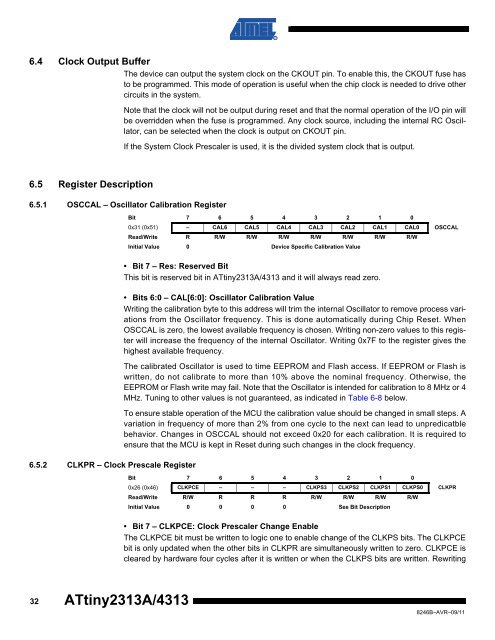
6.4 Clock Output Buffer<br />
The device can output the system clock on the CKOUT pin. To enable this, the CKOUT fuse has<br />
to be programmed. This mode of operation is useful when the chip clock is needed to drive other<br />
circuits in the system.<br />
Note that the clock will not be output during reset and that the normal operation of the I/O pin will<br />
be overridden when the fuse is programmed. Any clock source, including the internal RC Oscillator,<br />
can be selected when the clock is output on CKOUT pin.<br />
If the System Clock Prescaler is used, it is the divided system clock that is output.<br />
6.5 Register Description<br />
6.5.1 OSCCAL – Oscillator Calibration Register<br />
Bit 7 6 5 4 3 2 1 0<br />
0x31 (0x51) – CAL6 CAL5 CAL4 CAL3 CAL2 CAL1 CAL0 OSCCAL<br />
Read/Write R R/W R/W R/W R/W R/W R/W R/W<br />
Initial Value 0 Device Specific Calibration Value<br />
6.5.2 CLKPR – Clock Prescale Register<br />
• Bit 7 – Res: Reserved Bit<br />
This bit is reserved bit in <strong>ATtiny2313A</strong>/<strong>4313</strong> and it will always read zero.<br />
• Bits 6:0 – CAL[6:0]: Oscillator Calibration Value<br />
Writing the calibration byte to this address will trim the internal Oscillator to remove process variations<br />
from the Oscillator frequency. This is done automatically during Chip Reset. When<br />
OSCCAL is zero, the lowest available frequency is chosen. Writing non-zero values to this register<br />
will increase the frequency of the internal Oscillator. Writing 0x7F to the register gives the<br />
highest available frequency.<br />
The calibrated Oscillator is used to time EEPROM and Flash access. If EEPROM or Flash is<br />
written, do not calibrate to more than 10% above the nominal frequency. Otherwise, the<br />
EEPROM or Flash write may fail. Note that the Oscillator is intended for calibration to 8 MHz or 4<br />
MHz. Tuning to other values is not guaranteed, as indicated in Table 6-8 below.<br />
To ensure stable operation of the MCU the calibration value should be changed in small steps. A<br />
variation in frequency of more than 2% from one cycle to the next can lead to unpredicatble<br />
behavior. Changes in OSCCAL should not exceed 0x20 for each calibration. It is required to<br />
ensure that the MCU is kept in Reset during such changes in the clock frequency.<br />
Bit 7 6 5 4 3 2 1 0<br />
0x26 (0x46) CLKPCE – – – CLKPS3 CLKPS2 CLKPS1 CLKPS0 CLKPR<br />
Read/Write R/W R R R R/W R/W R/W R/W<br />
Initial Value 0 0 0 0 See Bit Description<br />
• Bit 7 – CLKPCE: Clock Prescaler Change Enable<br />
The CLKPCE bit must be written to logic one to enable change of the CLKPS bits. The CLKPCE<br />
bit is only updated when the other bits in CLKPR are simultaneously written to zero. CLKPCE is<br />
cleared by hardware four cycles after it is written or when the CLKPS bits are written. Rewriting<br />
32<br />
<strong>ATtiny2313A</strong>/<strong>4313</strong><br />
8246B–AVR–09/11