deva.metal Handbuch EN für GGB - Supresores
deva.metal Handbuch EN für GGB - Supresores
deva.metal Handbuch EN für GGB - Supresores

You also want an ePaper? Increase the reach of your titles
YUMPU automatically turns print PDFs into web optimized ePapers that Google loves.
Machining allowance for precision bearings<br />
Precision bearings with an assembled bore tolerance of<br />
IT7 or IT6 are obtained by finish machining the bearing<br />
bore after assembly in the housing. In this case a<br />
machining allowance of 0.15 - 0.2 mm is recommended.<br />
Wall thickness<br />
The bearing wall thickness must be sufficient to meet<br />
both the manufacturing and application strength<br />
requirements. Table 5.3 gives the recommended<br />
minimum wall thickness for <strong>deva</strong>.<strong>metal</strong> ® bearings<br />
according to the specific load and bearing diameter.<br />
Specific load (MPa)<br />
< 10<br />
10 - 25<br />
25 - 50<br />
> 50<br />
D 1<br />
= Bearing inner diameter<br />
Recommended minimum<br />
wall thickness<br />
√ 0.5 D 1<br />
√ 0.6 D 1<br />
√ 0.8 D 1<br />
Table 5.3 – Wall thickness of <strong>deva</strong>.<strong>metal</strong> ® bearings<br />
√<br />
D 1<br />
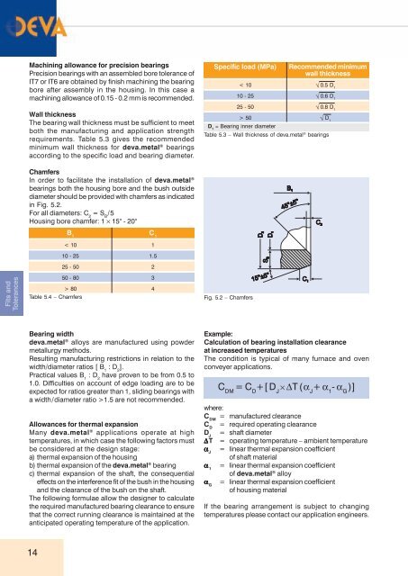
Chamfers<br />
In order to facilitate the installation of <strong>deva</strong>.<strong>metal</strong> ®<br />
bearings both the housing bore and the bush outside<br />
diameter should be provided with chamfers as indicated<br />
in Fig. 5.2.<br />
For all diameters: C 2<br />
= S B<br />
/5<br />
Housing bore chamfer: 1 × 15° - 20°<br />
B 1<br />
C 1<br />
< 10<br />
1<br />
10 - 25<br />
1.5<br />
25 - 50<br />
2<br />
Fits and<br />
Tolerances<br />
50 - 80<br />
> 80<br />
Table 5.4 – Chamfers<br />
3<br />
4<br />
Fig. 5.2 – Chamfers<br />
Bearing width<br />
<strong>deva</strong>.<strong>metal</strong> ® alloys are manufactured using powder<br />
<strong>metal</strong>lurgy methods.<br />
Resulting manufacturing restrictions in relation to the<br />
width/diameter ratios [ B 1<br />
: D 2<br />
].<br />
Practical values B 1<br />
: D 2<br />
have proven to be from 0.5 to<br />
1.0. Difficulties on account of edge loading are to be<br />
expected for ratios greater than 1, sliding bearings with<br />
a width/diameter ratio >1.5 are not recommended.<br />
Allowances for thermal expansion<br />
Many <strong>deva</strong>.<strong>metal</strong> ® applications operate at high<br />
temperatures, in which case the following factors must<br />
be considered at the design stage:<br />
a) thermal expansion of the housing<br />
b) thermal expansion of the <strong>deva</strong>.<strong>metal</strong> ® bearing<br />
c) thermal expansion of the shaft, the consequential<br />
effects on the interference fit of the bush in the housing<br />
and the clearance of the bush on the shaft.<br />
The following formulae allow the designer to calculate<br />
the required manufactured bearing clearance to ensure<br />
that the correct running clearance is maintained at the<br />
anticipated operating temperature of the application.<br />
Example:<br />
Calculation of bearing installation clearance<br />
at increased temperatures<br />
The condition is typical of many furnace and oven<br />
conveyer applications.<br />
C DM<br />
=C D<br />
+[D J<br />
× ΔT(α J<br />
+ α 1<br />
- α G<br />
)]<br />
where:<br />
C DM<br />
= manufactured clearance<br />
C D<br />
= required operating clearance<br />
D J<br />
= shaft diameter<br />
ΔT = operating temperature – ambient temperature<br />
α J<br />
= linear thermal expansion coefficient<br />
of shaft material<br />
α 1<br />
= linear thermal expansion coefficient<br />
of <strong>deva</strong>.<strong>metal</strong> ® alloy<br />
α G<br />
= linear thermal expansion coefficient<br />
of housing material<br />
If the bearing arrangement is subject to changing<br />
temperatures please contact our application engineers.<br />
14