Shallow Well Jet Pumps - Pump Express
Shallow Well Jet Pumps - Pump Express
Shallow Well Jet Pumps - Pump Express

Create successful ePaper yourself
Turn your PDF publications into a flip-book with our unique Google optimized e-Paper software.
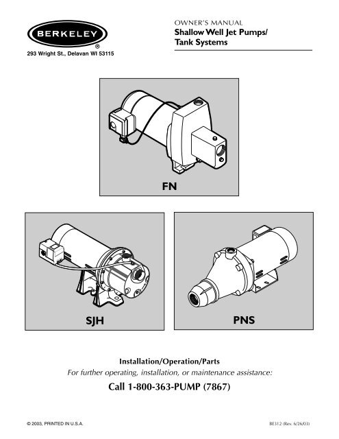
293 Wright St., Delavan WI 53115<br />
OWNER’S MANUAL<br />
<strong>Shallow</strong> <strong>Well</strong> <strong>Jet</strong> <strong><strong>Pump</strong>s</strong>/<br />
Tank Systems<br />
FN<br />
SJH<br />
PNS<br />
Installation/Operation/Parts<br />
For further operating, installation, or maintenance assistance:<br />
Call 1-800-363-PUMP (7867)<br />
© 2003, PRINTED IN U.S.A. BE312 (Rev. 6/26/03)
Safety 2<br />
READ AND FOLLOW<br />
SAFETY INSTRUCTIONS!<br />
This is the safety alert symbol. When you see this<br />
symbol on your pump or in this manual, look for<br />
one of the following signal words and be alert to the<br />
potential for personal injury:<br />
warns about hazards that will cause serious<br />
personal injury, death or major property damage if<br />
ignored.<br />
warns about hazards that can cause serious<br />
personal injury, death or major property damage if<br />
ignored.<br />
warns about hazards that will or can cause<br />
minor personal injury or property damage if ignored.<br />
The label NOTICE indicates special instructions which<br />
are important but not related to hazards.<br />
Carefully read and follow all safety instructions in this<br />
manual and on pump.<br />
Keep safety labels in good condition.<br />
Replace missing or damaged safety labels.<br />
ELECTRICAL SAFETY<br />
Capacitor voltage may be hazardous. To<br />
discharge motor capacitor, hold insulated handle screwdriver<br />
BY THE HANDLE and short capacitor terminals<br />
together. Do not touch metal screwdriver blade or capacitor<br />
terminals. If in doubt, consult a qualified electrician.<br />
GENERAL SAFETY<br />
Do not touch an operating motor. Modern<br />
motors are designed to operate at high temperatures. To<br />
avoid burns when servicing pump, allow it to cool for 20<br />
minutes after shut-down before handling.<br />
Do not allow pump or any system component to freeze.<br />
To do so will void warranty.<br />
<strong>Pump</strong> water only with this pump.<br />
Periodically inspect pump and system components.<br />
Wear safety glasses at all times when working on pumps.<br />
Keep work area clean, uncluttered and properly lighted;<br />
store properly all unused tools and equipment.<br />
Keep visitors at a safe distance from the work areas.<br />
Make workshops childproof; use padlocks and master<br />
switches; remove starter keys.<br />
<strong>Pump</strong> body may explode if used as a<br />
booster pump unless relief valve capable of passing full<br />
pump flow at 75 psi is installed.<br />
WARNING<br />
Hazardous voltage.<br />
Can shock, burn, or<br />
cause death.<br />
Ground pump before<br />
connecting to power<br />
supply. Disconnect power<br />
before working on pump,<br />
motor or tank.<br />
Wire motor for correct<br />
voltage. See “Electrical”<br />
section of this manual<br />
and motor nameplate.<br />
Ground motor before<br />
connecting to power<br />
supply.<br />
Meet National Electrical<br />
Code, Canadian<br />
Electrical Code, and local<br />
codes for all wiring.<br />
Follow wiring instructions<br />
in this manual<br />
when connecting motor to<br />
power lines.<br />
WARNING<br />
Hazardous pressure!<br />
Install pressure relief<br />
valve in discharge pipe.<br />
Release all pressure on<br />
system before working on<br />
any component.
Table of Contents 3<br />
Thank you for purchasing a top quality, factory tested pump.<br />
Page<br />
General Safety .....................................................................................................2<br />
Warranty..............................................................................................................3<br />
Installation ........................................................................................................4,5<br />
Connecting Discharge Piping...............................................................................6<br />
Electrical...........................................................................................................7,8<br />
Preparing To Start The <strong>Pump</strong>................................................................................8<br />
Troubleshooting ...................................................................................................9<br />
Repair Parts .................................................................................................10-13<br />
ATTACH ORIGINAL RECEIPT HERE FOR WARRANTY CONSIDERATION.<br />
Berkeley/Wicor Canada Company (“Wicor”) warrants to the original<br />
consumer purchaser (“Purchaser”) of its products that they are free<br />
from defects in material or workmanship.<br />
If within twelve (12) months from the date of installation or twentyfour<br />
(24) months from the date of manufacture any such product shall<br />
prove to be defective, it shall be repaired or replaced at<br />
Berkeley’s/Wicor’s option, subject to the terms and conditions set<br />
forth below.<br />
General Terms and Conditions<br />
Purchaser must pay all labor and shipping charges necessary to<br />
replace product covered by this warranty. This warranty shall not<br />
apply to products which, in the sole judgement of Berkeley/Wicor,<br />
have been subject to negligence, abuse, accident, misapplication, tampering,<br />
alteration; nor due to improper installation, operation, maintenance<br />
or storage; nor to other than normal application, use or service,<br />
including but not limited to, operational failures caused by corrosion,<br />
rust or other foreign materials in the system, or operation at<br />
pressures in excess of recommended maximums.<br />
Requests for service under this warranty shall be made by contacting<br />
the installing Berkeley/Wicor dealer as soon as possible after the discovery<br />
of any alleged defect. Berkeley/Wicor will subsequently take<br />
Berkeley Limited Warranty<br />
corrective action as promptly as reasonably possible. No requests for<br />
service under this warranty will be accepted if received more than 30<br />
days after the term of the warranty.<br />
The warranty on all three phase submersible motors is void if threeleg<br />
overload protection of recommended size is not used.<br />
This warranty sets forth Berkeley’s/Wicor’s sole obligation and purchaser’s<br />
exclusive remedy for defective products.<br />
BERKELEY/WICOR SHALL NOT BE LIABLE FOR ANY CONSE-<br />
QUENTIAL, INCIDENTAL, OR CONTINGENT DAMAGES WHAT-<br />
SOEVER.<br />
THE FOREGOING WARRANTIES ARE EXCLUSIVE AND IN LIEU<br />
OF ALL OTHER EXPRESS WARRANTIES. IMPLIED WARRANTIES,<br />
INCLUDING BUT NOT LIMITED TO THE IMPLIED WARRANTIES<br />
OF MERCHANTABILITY AND FITNESS FOR A PARTICULAR PUR-<br />
POSE, SHALL NOT EXTEND BEYOND THE DURATION OF THE<br />
APPLICABLE EXPRESS WARRANTIES PROVIDED HEREIN.<br />
Some states do not allow the exclusion or limitation of incidental or<br />
consequential damages or limitations on how long an implied warranty<br />
lasts, so the above limitations or exclusions may not apply to<br />
you.This warranty gives you specific legal rights and you may also have<br />
other rights which vary from state to state.<br />
In the U.S.: Berkeley, 293 Wright St., Delavan,WI 53115<br />
In Canada:Wicor Canada Company, 1800 Courtney Park Drive East, Unit 5-7, Mississauga, Ontario L5T 1W1
Installation 4<br />
To Household<br />
Water System<br />
Not<br />
to<br />
Scale<br />
2346 0396<br />
<strong>Pump</strong> Priming<br />
Tee and Plug<br />
Suction Pipe<br />
From <strong>Well</strong><br />
Priming<br />
Tee and<br />
Plug<br />
Check<br />
Valve<br />
Drive point<br />
below water<br />
level<br />
Drive<br />
Coupling<br />
Drive<br />
Point<br />
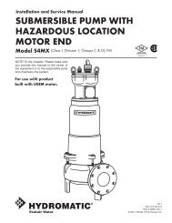
Figure 1: Driven Point Installation<br />
To Household<br />
Water System<br />
2347 0396<br />
Not<br />
to<br />
Scale<br />
Check<br />
Valve<br />
<strong>Pump</strong> Priming<br />
Tee and Plug<br />
10'<br />
Min.<br />
5–10'<br />
Suction Pipe<br />
From <strong>Well</strong><br />
Priming<br />
Tee and<br />
Plug<br />
Sanitary<br />
<strong>Well</strong> Seal<br />
<strong>Well</strong><br />
Casing<br />
Foot<br />
Valve<br />
Figure 2: Cased <strong>Well</strong> Installation<br />
REPLACING AN OLD PUMP<br />
Hazardous voltage. Disconnect power to pump before working<br />
on pump or motor.<br />
Step 1. Drain and remove the old pump. Check the old pipe for scale, lime,<br />
rust, etc., and replace it if necessary.<br />
Step 2. Install the pump in the system. Make sure that all pipe joints in the<br />
suction pipe are air-tight as well as water tight. If the suction pipe<br />
can suck air, the pump will not be able to pull water from the well.<br />
Step 3. Adjust the pump mounting height so that the plumbing connections<br />
do not put a strain on the pump body. Support the pipe so that the<br />
pump body does not take the weight of piping or fittings.<br />
You have just completed the well plumbing for your new shallow<br />
well jet pump. Please go to Page 6 for discharge pipe and tank<br />
connections.<br />
WELL POINT (DRIVEN POINT) INSTALLATION<br />
(FIGURE 1)<br />
Step 1. Drive the well, using “drive couplings” and a “drive cap”. “Drive<br />
fittings” are threaded all the way through and allow the pipe ends to<br />
butt against each other so that the driving force of the maul is carried<br />
by the pipe and not by the threads. The ordinary fittings found<br />
in hardware stores are not threaded all the way through the fitting<br />
and can collapse under impact. “Drive fittings” are also smoother<br />
than standard plumbing fittings, making ground penetration easier.<br />
Step 2. Mount the pump as close to the well as possible<br />
Step 3. Use the fewest possible fittings (especially elbows) when connecting<br />
the pipe from the well point to the pump suction port. The suction<br />
pipe should be at least as large as the suction port on the pump<br />
(include a check valve if your pump is not equipped with one – see<br />
Figure 1). Support the pipe so that there are no dips or sags in the<br />
pipe, so it doesn’t strain the pump body, and so that it slopes slightly<br />
upward from the well to the pump (high spots can cause air<br />
pockets which can air lock the pump). Seal the suction pipe joints<br />
with teflon tape or a teflon based pipe joint compound. Joints must<br />
be air- and water-tight. If the suction pipe can suck air, the pump<br />
cannot pull water from the well. If one well point does not supply<br />
enough water, consider connecting two or three well points to one<br />
suction pipe.<br />
You have just completed the suction piping for your new shallow<br />
well jet pump. Please go to Page 6 for discharge pipe and tank<br />
connections.<br />
CASED WELL INSTALLATION, 2” OR LARGER<br />
CASING (FIGURE 2)<br />
Step 1. Mount the pump as close to the well as possible.<br />
Step 2. Assemble the foot valve, strainer, and well pipe (see Figure 2). Make<br />
sure that the foot valve works freely.<br />
Step 3. Lower the pipe into the well until the strainer is five feet above the<br />
bottom of the well. It should also be at least 10 feet below the well’s<br />
water level while the pump is running in order to prevent the pump<br />
from sucking air. Install a sanitary well seal.
Installation 5<br />
To Household<br />
Water System<br />
Check<br />
Valve<br />
<strong>Pump</strong> Priming<br />
Tee and Plug<br />
Suction Pipe<br />
From <strong>Well</strong><br />
Priming<br />
Tee and<br />
Plug<br />
Step 4. Install a priming tee, priming plug, and suction pipe to the pump<br />
(see Figure 2). Connect the pipe from the well to the pump suction<br />
port, using the fewest possible fittings – especially elbows – as fittings<br />
increase friction in the pipe (however, include a foot valve –<br />
see Figure 2). The suction pipe should be at least as large as the<br />
suction port on the pump. Use teflon tape or a teflon-based pipe<br />
joint compound on threaded pipe joints. Support the pipe so that<br />
there are no dips or sags in the pipe, so it doesn’t strain the pump<br />
body, and so that it slopes slightly upward from the well to the<br />
pump (high spots can cause air pockets which can air lock the<br />
pump). Seal the suction pipe joints with teflon tape or a teflon<br />
based pipe joint compound. Joints must be air- and water-tight. If<br />
the suction pipe can suck air, the pump cannot pull water from the<br />
well.<br />
You have just completed the suction piping for your new shallow<br />
well jet pump. Please go to Page 6 for discharge pipe and tank<br />
connections.<br />
Not<br />
to<br />
Scale<br />
10'<br />
Min.<br />
5–10'<br />
2348 0396<br />
Foot<br />
Valve<br />
Screen<br />
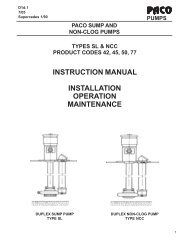
Figure 3: Surface Water Installation<br />
INSTALLATION FOR SURFACE WATER (FIGURE 3)<br />
Step 1. The pump should be installed as close to the water as possible,<br />
with the fewest possible fittings (especially elbows) in the suction<br />
pipe. The suction pipe should be at least as large as the suction port<br />
on the pump.<br />
Step 2. Assemble a foot valve and suction pipe (see Figure 3). Make sure<br />
that the foot valve works freely. Use teflon tape or a teflon-based<br />
pipe joint compound on threaded pipe joints. Protect the foot valve<br />
assembly from fish, trash, etc, by installing a screen around it (see<br />
Figure 3).<br />
Step 3. Lower the pipe into the water until the strainer is five feet above the<br />
bottom. It should also be at least 10 feet below the water level in<br />
order to prevent the pump from sucking air.<br />
Step 4. Install a priming tee, priming plug, and suction pipe to the pump<br />
(see Figure 3). Support the pipe so that there are no dips or sags in<br />
the pipe, so it doesn’t strain the pump body, and so that it slopes<br />
slightly upward from the well to the pump (high spots can cause air<br />
pockets which can air lock the pump). Seal the suction pipe joints<br />
with teflon tape or a teflon based pipe joint compound. Joints must<br />
be air- and water-tight. If the suction pipe can suck air, the pump<br />
cannot pull water from the well.<br />
You have just completed the plumbing for your new shallow well jet<br />
pump. Please go to Page 6 for discharge pipe and tank connections.
Discharge Pipe and Pressure Tank Connections 6<br />
Pressure<br />
Switch<br />
To Household<br />
Water System<br />
Check<br />
Valve<br />
<strong>Pump</strong> Priming<br />
Tee and Plug<br />
From <strong>Well</strong><br />
PRE-CHARGE TANK CONNECTION (FIGURE 4)<br />
Step 1. Install two tees in the pump discharge port (see Figure 4). The pipe<br />
size must be at least as large as the discharge port.<br />
Step 2. Run a pipe or reinforced hose from one arm of the first tee to the<br />
port on the pre-charged tank.<br />
Step 3. Connect the other end of the discharge tee to your plumbing system.<br />
Step 4. Check the pre-charge of air in the tank with an ordinary tire gauge.<br />
The pre-charge should be 2 PSI less than the cut-in setting of the<br />
pump’s pressure switch. The pre-charge is measured when there is<br />
no water pressure in the tank. Your new pump has a 30/50 PSI<br />
switch, so adjust the tank pre-charge pressure to 28 PSI.<br />
Congratulations! You have just completed the tank connection for<br />
your jet pump.<br />
Please go to Page 7 for electrical hookup.<br />
2349 0396<br />
Figure 4: Pre-charged Tank Connections<br />
To Household<br />
Water System<br />
<strong>Pump</strong><br />
Priming Tee<br />
and Plug<br />
Air Volume<br />
Control<br />
Air Volume<br />
Control Tube<br />
STANDARD TANK CONNECTION (FIGURE 5)<br />
Step 1. Install one tee in the pump discharge port (see Figure 5).<br />
Step 2. Run a pipe from the pump discharge port to the inlet port of your<br />
tank. The pipe size must be at least as large as the discharge port.<br />
Step 3. Remove the 1/8” NPT pipe plug from the pump Air Volume Control<br />
(AVC) port (see Figure 5). Run tubing from the pump’s AVC port<br />
(see Figure 5) to the port on the AVC mounted on the tank. See<br />
instructions provided with tank and AVC for details. AVC port location<br />
will vary, depending on your pump model (see exploded view,<br />
Page 9).<br />
Congratulations! You have just completed the tank connection for<br />
your jet pump.<br />
Please go to Page 7 for electrical hookup.<br />
Pressure<br />
Switch<br />
Check<br />
Valve<br />
2350 0396<br />
From<br />
<strong>Well</strong><br />
Figure 5: Standard Tank Connections<br />
Sealing Pipe Joints<br />
Use Teflon tape or Teflon based joint compounds for<br />
making all threaded connections. Make sure that all pipe joints<br />
in the suction pipe are air tight as well as water tight. If the<br />
suction pipe can suck air, the pump will not be able to pull<br />
water from the well.<br />
Wiring Chart – Recommended Wire and Fuse Sizes<br />
DISTANCE IN FEET(METERS) FROM MOTOR TO SUPPLY<br />
Branch<br />
Max. Fuse<br />
0 - 100 101 - 200 201 - 300 301 - 400 401 - 500<br />
Motor Load Rating (0 - 30) (31 - 61) (62 - 91) (92 - 122) (123 - 152)<br />
Model HP Volts Amp Amp AWG WIRE SIZE (mm 2 )<br />
5FN-L 1/2 115/230 9.4/4.7 15/15 14/14(2/2) 10/14(5.5/2) 10/14(5.5/2) 6/14(14/2) 6/12(14/3)<br />
7FN-L 3/4 115/230 12.4/6.2 20/15 12/14(3/2) 10/14(5.5/2) 8/14(8.4/2) 6/12(14/3) 6/12(14/3)<br />
5PN, 05PNS11S 1/2 115/230 9.4/4.7 15/15 14/14(2/2) 10/14(5.5/2) 10/14(5.5/2) 6/14(14/2) 6/12(14/3)<br />
7PN, 07PNS11S 3/4 115/230 12.2/6.1 20/15 12/14(3/2) 10/14(5.5/2) 8/14(8.4/2) 6/12(14/3) 6/12(14/3)<br />
07SJH11C 3/4 115/230 14.8/7.4 20/15 12/14(3/2) 8/14(8.4/2) 6/14(14/2) 6/12(4/3) 4/10(21/5.5)<br />
10SJH11C 1 115/230 19.2/9.6 25/15 10/14(5.5/2) 8/14(8.4/2) 6/12(14/3) 4/10(21/5.5) 4/10(21/5.5)
Electrical 7<br />
Disconnect power before working on pump, motor, pressure switch, or wiring.<br />
Your Motor Terminal Board (under the motor end cover)<br />
and Pressure Switch look like one of those shown below.<br />
Convert to 115 Volts as shown. Do not change motor<br />
wiring if line voltage is 230 Volts or if you have a single<br />
voltage motor. Connect power supply as shown for your<br />
type of switch and your supply voltage.<br />
230 Volt to 115 Volt Conversion. Move plug to change voltage.<br />
Ground<br />
Screw<br />
230V<br />
115V<br />
230 V<br />
230 Volt to 115 Volt Conversion. Move plug to change voltage.<br />
1. Pull plug<br />
2. Plug in again<br />
straight<br />
with arrow<br />
Ground<br />
out from<br />
on plug<br />
Screw<br />
terminal<br />
pointing to<br />
board.<br />
'115 Volts'.<br />
1.<br />
230V<br />
15<br />
230<br />
Volts<br />
115<br />
Volts<br />
A<br />
L2<br />
L1<br />
115 V<br />
230V<br />
115V<br />
Power Supply<br />
Wires<br />
230 Volt to 115 Volt Conversion, Plug-in Type:<br />
Move plug to change voltage.<br />
L2<br />
230 115<br />
L1<br />
Figure 6: Motor wiring connections through Pressure<br />
Switch. Match motor voltage to line voltage.<br />
2.<br />
Grounding Point<br />
Power Supply Wires<br />
230V<br />
15V<br />
230<br />
Volts<br />
115<br />
Volts<br />
L2<br />
L2<br />
A<br />
230 115<br />
230 115<br />
2<br />
A<br />
1<br />
L1<br />
L1<br />
L<br />
3962 0401 A<br />
230 V<br />
115 V<br />
3781 1000<br />
Motor wires connect here.<br />
Power supply wires connect here.<br />
230 Volt: Connect 2 hot wires (black and red)<br />
here and cap the white (neutral) wire. It does<br />
not matter which wire goes to which screw.<br />
115 Volt: Connect one hot wire (black or red)<br />
to one of these screws (it doesn't matter<br />
which one). Connect the white (neutral) wire<br />
to the other screw. Cap any remaining<br />
black or red wires.<br />
Hazardous voltage. Can shock, burn, or<br />
kill. Connect ground wire before connecting power supply<br />
wires. Use the wire size (including the ground wire)<br />
specified in the wiring chart. If possible, connect the<br />
pump to a separate branch circuit with no other appliances<br />
on it.<br />
supply line.<br />
Clamp the power cable to prevent strain<br />
on the terminal screws.<br />
Connect the green (or bare copper) ground wire<br />
to the green ground screw.<br />
Motor wires connect here.<br />
Power supply wires connect here.<br />
230 Volt: Connect 2 hot wires (black and red)<br />
here and cap the white (neutral) wire. It does<br />
not matter which wire goes to which screw.<br />
115 Volt: Connect one hot wire (black or red)<br />
to one of these screws (it doesn't matter<br />
which one). Connect the white (neutral) wire<br />
to the other screw. Cap any remaining<br />
black or red wires.<br />
Clamp the power cable to prevent strain<br />
on the terminal screws.<br />
Connect the green (or bare copper) ground wire<br />
to the green ground screw.<br />
Explosion hazard. Do not ground to a gas<br />
WIRING CONNECTIONS<br />
3187 0398<br />
Fire hazard. Incorrect voltage can cause a<br />
fire or seriously damage the motor and voids the warranty.<br />
The supply voltage must be within ±10% of the motor<br />
nameplate voltage.<br />
NOTICE: Dual-voltage motors are factory wired for 230<br />
volts. If necessary, reconnect the motor for 115 volts, as<br />
shown. Do not alter the wiring in single voltage motors.
Electrical / Preparing to Start the <strong>Pump</strong> 8<br />
Install, ground, wire, and maintain your pump in compliance with the<br />
National Electrical Code (NEC) in the U.S., or the Canadian Electrical Code<br />
(CEC), as applicable, and with all local codes and ordinances that apply.<br />
Consult your local building inspector for code information.<br />
Connection Procedure:<br />
Step 1. Connect the ground wire first as shown in Figure 6. The ground<br />
wire must be a solid copper wire at least as large as the power supply<br />
wires.<br />
Step 2. There must be a solid metal connection between the pressure<br />
switch and the motor for motor grounding protection. If the pressure<br />
switch is not connected to the motor, connect the green<br />
ground screw in the switch to the green ground screw under the<br />
motor end cover. Use a solid copper wire at least as large as the<br />
power supply wires.<br />
Step 3. Connect the ground wire to a grounded lead in a service panel, to a<br />
metal underground water pipe, to a metal well casing at least ten<br />
feet (3M) long, or to a ground electrode provided by the power<br />
company or the hydro authority.<br />
Step 4. Connect the power supply wires to the pressure switch as shown in<br />
Figure 6.<br />
PREPARING TO START THE PUMP<br />
Never run pump dry. Running pump without water may<br />
cause pump to overheat, damaging seal and possibly causing burns to persons<br />
handling pump. Fill pump with water before starting.<br />
Figure 7: Prime the <strong>Pump</strong><br />
Fill pump<br />
and piping<br />
through<br />
priming tee.<br />
Never run pump against closed discharge. To do so can boil<br />
water inside pump, causing hazardous pressure in unit, risk of explosion<br />
and possibly scalding persons handling pump.<br />
Step 1. Remove the priming plug from the priming tee and fill the pump.<br />
Fill all piping between the pump and the well and make sure that<br />
all piping in the well is full. If you have also installed a priming tee<br />
in the suction piping, remove the plug from the tee and fill the suction<br />
piping.<br />
Step 2. Replace all fill plugs.<br />
Step 3. Power on! Start the pump. If you don’t have water after 2 or 3 minutes,<br />
stop the pump and remove the fill plugs. Refill the pump and<br />
piping. You may have to repeat this several times in order to get all<br />
the trapped air out of the piping. A pump lifting water 25’ may take<br />
as long as 15 minutes to prime.<br />
Step 4. After the pump has built up pressure in the system and shut off,<br />
check the pressure switch operation by opening a faucet or two and<br />
running enough water out to bleed off pressure until the pump<br />
starts. The pump should start when pressure drops to 30 PSI and<br />
stop when pressure reaches 50 PSI. Run the pump through one or<br />
two complete cycles to verify correct operation. This will also help<br />
clean the system of dirt and scale dislodged during installation.<br />
Congratulations on a successful installation.<br />
If you were unsuccessful, please refer to the Troubleshooting section<br />
(Page 9).
Troubleshooting 9<br />
SYMPTOM POSSIBLE CAUSE(S) CORRECTIVE ACTION<br />
Motor will not run Disconnect switch is off Be sure switch is on.<br />
Fuse is blown or circuit breaker tripped Replace fuse or reset circuit breaker.<br />
Starting switch is defective<br />
DISCONNECT POWER; Replace starting switch.<br />
Wires at motor are loose,<br />
Refer to instructions on wiring (Page 7). DISCONNECT POWER; check and<br />
disconnected, or wired incorrectly tighten all wiring.<br />
Pressure switch contacts are dirty<br />
Capacitor voltage may be hazardous. To discharge<br />
capacitor, hold insulated handle screwdriver BY THE HANDLE and<br />
short capacitor terminals together. Do not touch metal screwdriver<br />
blade or capacitor terminals. If in doubt, consult a qualified electrician.<br />
DISCONNECT POWER and file contacts with emery board or nail file.<br />
Motor runs hot and Motor is wired incorrectly Refer to instructions on wiring.<br />
overload kicks off Voltage is too low Check with power company. Install heavier wiring if wire size is too small<br />
(See Electrical / Wiring Chart).<br />
<strong>Pump</strong> cycles too frequently<br />
See section below on too frequent cycling.<br />
Motor runs but no <strong>Pump</strong> in new installation did In new installation:<br />
water is delivered* not pick up prime through:<br />
1. Improper priming 1. Re-prime according to instructions.<br />
2. Air leaks 2. Check all connections on suction line, AVC, and ejector with<br />
soapy water or shaving cream.<br />
* (Note: Stop pump; 3. Leaking foot valve or check valve 3. Replace foot valve or check valve.<br />
then check prime <strong>Pump</strong> has lost prime through:<br />
In installation already in use:<br />
before looking for 1. Air leaks 1. Check all connections on suction line and shaft seal.<br />
other causes.<br />
2. Water level below suction pipe inlet 2. Lower suction line into water and re-prime. If receding water level<br />
Unscrew priming<br />
in well exceeds 25’ (7.6M), a deep well pump is needed.<br />
plug and see if water<br />
Foot valve or strainer is plugged<br />
Clean foot valve or strainer.<br />
is in priming hole).<br />
Ejector or impeller is plugged<br />
Clean ejector or impeller.<br />
Check valve or foot valve is stuck shut Replace check valve or foot valve.<br />
Pipes are frozen<br />
Thaw pipes. Bury pipes below frost line. Heat pit or pump house.<br />
Foot valve and/or strainer are<br />
Raise foot valve and/or strainer above bottom of water source.<br />
buried in sand or mud<br />
Clean foot valve and strainer.<br />
Water level is too low for shallow well A deep well jet package may be needed (over 25 ft. to water)<br />
setup to deliver water<br />
to deliver water.<br />
<strong>Pump</strong> does not Water level in well is lower than A deep well jet will be needed if your well is more than 25’ (7.6M)<br />
deliver water to full estimated depth to water.<br />
capacity Steel piping (if used) is corroded or Replace with plastic pipe where possible, otherwise with new steel pipe.<br />
limed, causing excess friction<br />
Piping is too small in size<br />
Use larger piping.<br />
Packed well point<br />
Backflush well point or sink new point.<br />
<strong>Pump</strong> delivers water but Pressure switch is out of adjustment or DISCONNECT POWER; adjust or replace pressure switch.<br />
does not shut off or contacts are welded together<br />
pump cycles too Faucets have been left open Close faucets.<br />
frequently Venturi, nozzle or impeller is clogged Clean venturi, nozzle or impeller.<br />
Standard pressure tank is waterlogged Drain tank to air volume control port. Check AVC for defects. Check<br />
and has no air cushion<br />
all connections for air leaks.<br />
Pipes leak<br />
Check connections.<br />
Foot valves leak<br />
Replace foot valve.<br />
Air charge too low in pre-charged tank DISCONNECT POWER and open faucets until all pressure is relieved.<br />
Using tire pressure gauge, check air pressure in tank at valve stem<br />
located on the tank. If less than pressure switch cut-in setting (30-50<br />
PSI), pump air into tank from outside source until air pressure is 2 PSI<br />
less than cut-in setting of switch. Check air valve for leaks (use soapy<br />
solution) and replace core if necessary.<br />
Air spurts from faucets <strong>Pump</strong> is picking up prime When pump has picked up prime, it should pump solid water with no air.<br />
Leak in suction side of pump<br />
Suction pipe is sucking air. Check joints for leaks with soapy water.<br />
<strong>Well</strong> is gaseous<br />
Consult factory about installing a sleeve in the well<br />
Intermittent over-pumping of well. Lower foot valve if possible, otherwise restrict pump discharge<br />
(Water drawn down below foot valve.)
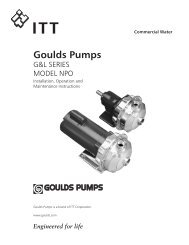
Repair Parts 10<br />
1<br />
16<br />
Exploded View<br />
5FN / 5FN-L<br />
7FN / 7FN-L<br />
2<br />
13<br />
3<br />
4<br />
5<br />
6<br />
7A<br />
12<br />
16<br />
8 9<br />
11<br />
7B<br />
14 15 2331 0296 BK<br />
9A<br />
10<br />
9B<br />
10<br />
10<br />
REPAIR PARTS LIST<br />
5FN<br />
7FN<br />
Key Part No. 5FN-L 7FN-L<br />
No. Description Used 1/2 HP 3/4 HP<br />
1 Motor 1 A100CLL A100DLL<br />
2 Water Slinger 1 17351-0009 17351-0009<br />
3 Seal Plate 1 N3-9 N3-9<br />
4 Seal Plate Gasket 1 N20-35 N20-35<br />
5 Shaft Seal 1 U109-6A U109-6A<br />
6 Impeller 1 J105-40P J105-42P<br />
7A Diffuser 1 L1-25P L1-25P<br />
7B Diffuser Gasket 1 N20-34 N20-34<br />
8 Barbed Fitting - Straight - 1/4” NPT 1 U111-211T U111-211T<br />
9 <strong>Pump</strong> Body - Assembly 1 N176-38 N126-38F<br />
9A Venturi (1) N32P-66 N32P-75<br />
9B Nozzle (1) N34P-17 N34P-21<br />
10 Pipe Plug - 1/4” NPT Hex Hd. 3 U78-941ZPV U78-941ZPV<br />
11 Tube 3/8” O.D. x 14-1/2” Lg. 1 U37-672P U37-672P<br />
12 Barbed Fitting – Elbow - 1/4” NPT 1 U111-212T U111-212T<br />
13 Pressure Switch 1 U217-1225 U27-1202<br />
14 Locknut - 1/2” 1 U36-112ZP U36-112ZP<br />
15 Connector 1 L43-5C L43-5C<br />
16 Hex Capscrew - 3/8” - 16 x 1-1/4” Lg. 4 U30-75ZP U30-75ZP<br />
• Pressure Gauge 1 U239-2 U239-2<br />
• Not illustrated.
Repair Parts 11<br />
19<br />
20<br />
21<br />
1<br />
2<br />
3<br />
4<br />
5A<br />
Exploded View<br />
07SJH11C - 3/4 HP<br />
07SJH11C115H - 3/4 HP<br />
10SJH11C - 1 HP<br />
5B<br />
6<br />
7<br />
18<br />
8<br />
17<br />
9<br />
16<br />
15<br />
10<br />
14<br />
13<br />
341 0397<br />
12<br />
11<br />
REPAIR PARTS LIST<br />
07SJH11C<br />
Key Part No. 07SJH11C115H 10SJH11C<br />
No. Description Used 3/4 HP 1 HP<br />
1 Motor 1 J218-1006 J218-1007<br />
2 Slinger 1 C69-7 C69-7<br />
3 Seal Plate 1 784S0070 784S0070<br />
4 O-Ring 1 111P0490 111P0490<br />
5A Shaft Seal Seat 1 111P0510 111P0510<br />
5B Shaft Seal Rotating 1 111P0500 111P0500<br />
6 Impeller 1 101P1720 101P1730<br />
7 Venturi 1 101P2900 101P2900<br />
8 O-Ring 1 111P1100 111P1100<br />
9 90° Hose Barb 1 171P4750T 171P4750T<br />
10 <strong>Pump</strong> Body 1 723S0850 723S0850<br />
11 Plug, Stainless Steel 1 121P2100 121P2100<br />
12 Washer 1 111P0990 111P0990<br />
13 Screw, Socket Head 8 121P0310 121P0310<br />
14 Base 1 C4-42P C4-42P<br />
15 Bolt 2 U30-73SS U30-73SS<br />
16 Pressure Switch Tube 1 U37-677P U37-677P<br />
17 1/4” NPT 90° Hose Barb 1 U111-212T U111-212T<br />
18 Nut 8 U36-207SS U36-207SS<br />
19 Pressure Switch 1 U217-1202 U217-1202<br />
20 1/2” Locknut 1 U36-112ZP U36-112ZP<br />
21 Connector 1 L43-5C L43-5C
Repair Parts 12<br />
28<br />
27<br />
1<br />
Exploded View<br />
05PNS11S / 5PN - 1/2 HP<br />
07PNS11S / 7PN - 3/4 HP<br />
2<br />
3<br />
4<br />
5<br />
6<br />
7<br />
8<br />
9<br />
10<br />
26<br />
14<br />
25<br />
24<br />
23<br />
22<br />
21<br />
20<br />
19<br />
1867 0795SR<br />
18<br />
15<br />
17<br />
16<br />
11<br />
AVC<br />
Port<br />
14<br />
13<br />
12<br />
REPAIR PARTS LIST<br />
05PNS11S 07PNS11S<br />
Key 5PN 7PN<br />
No. Part Description Qty. 1/2 HP 3/4 HP<br />
1 Motor 1 A100CLL A100DLL<br />
2 Water Slinger 1 17351-0009 17351-0009<br />
3 Seal Plate Assembly (Incl. #5) 1 N103-12PSS N103-12PSS<br />
4 Heat Sink 1 J3-2SS J3-2SS<br />
5 “O” Ring 1 U9-390 U9-390<br />
6 Shaft Seal 1 U109-6A U109-6A<br />
7 Impeller 1 J105-40PF J105-42PTB<br />
8 Rubber Pad 1 C35-41 C35-41<br />
9 Diffuser 1 N1-28P N1-28P<br />
10 Capscrew #10-16 Hex Head 2 U30-738SS U30-738SS<br />
11 <strong>Pump</strong> Body Assembly (incl. #12 thru #18) 1 N176-35P N176-35PA<br />
12 <strong>Pump</strong> Body 1 N76-35P N76-35P<br />
13 Pipe Plug 1/8” NPT Taped 1 WC78-41T WC78-41T<br />
14 Comp. Elbow 1/4” NPT w/TFE 2 U111-86T U111-86T<br />
15 Switch Tube 1 U37-670P U37-670P<br />
16 Gasket - Plastic 1 J20-18 J20-18<br />
17 <strong>Pump</strong> <strong>Jet</strong> Body Insert 1 N76-29P N76-29P<br />
18 Capscrew #10-16 4 U30-742SS U30-742SS<br />
19 Nozzle 1 N34P-17 N34P-19<br />
20 Venturi 1 N32P-78 N32P-66<br />
21 “O” Ring 1 U9-201 U9-201<br />
22 Base Assembly Painted 1 J104-9F J104-9F<br />
23 Lock Washer 3/8” 4 U43-12ZP U43-12ZP<br />
24 Nut 3/8-16 4 U36-38ZP U36-38ZP<br />
25 Rubber Pad 1 C35-5 C35-5<br />
26 Pressure Switch 1 U217-1216 U217-1216<br />
27 Locknut 1/2” 1 U36-112ZP U36-112ZP<br />
28 Connector 1/2” 1 L43-5C L43-5C
Repair Parts 13<br />
Exploded View<br />
07SJH11C115H<br />
4<br />
1<br />
5<br />
2<br />
6<br />
4<br />
3<br />
REPAIR PARTS LIST<br />
Key Part No.<br />
No. Description Used 07SJH11C115H<br />
1 1/2” NPT Pipe Plug 1 *<br />
2 Discharge Tee with Barb 1 U78-961P<br />
3 1” NPT Street Elbow 1 U78-974P<br />
4 Hose Clamp 1 *<br />
5 1” Reinforced Hose, 24-1/2” Long 1 U74-37V<br />
6 Tank Assembly 1 U231-360<br />
* Standard hardware item, purchase locally.