submersible pump with hazardous location motor end - Pump Express
submersible pump with hazardous location motor end - Pump Express
submersible pump with hazardous location motor end - Pump Express

You also want an ePaper? Increase the reach of your titles
YUMPU automatically turns print PDFs into web optimized ePapers that Google loves.
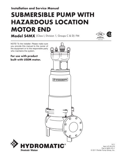
Installation and Service ManualSUBMERSIBLE PUMP WITHHAZARDOUS LOCATIONMOTOR ENDModel S4MX (Class I, Division 1, Groups C & D): FM(Hazardous LocationMotor End)NOTE! To the installer: Please make sureyou provide this manual to the owner ofthe equip ment or to the responsible partywho maintains the system.For use <strong>with</strong> productbuilt <strong>with</strong> USEM <strong>motor</strong>.3/11Item # E-03-475Part # 5625-475-1© 2011 Pentair <strong>Pump</strong> Group, Inc.
Single phase <strong>pump</strong>s <strong>with</strong> capacitorstart have a run and a start windingeach drawing a different current.To adequately protect thesewindings <strong>with</strong> the appropriateheaters, consult the factory.NOTE: red lead is alwaysstart wind ing of <strong>pump</strong> usingsingle phase.<strong>Pump</strong>Installationinstalling Sump Level ControlFloat Controls:In either simplex, duplex ortriplex systems the lower orturn-off control is to be set tomaintain a minimum level in thesump. This level shall be no morethan 3 1 ⁄4" from the top of the<strong>motor</strong> housing down to thesurface of the sewage.The second or turn-on control isset above the lower turn-offcontrol. The exact distancebetween the two floats must be acompromise between a fre quent<strong>pump</strong>ing cycle (10 starts per hourmax.) to control septicity, solidsand a slower cycle for energyecon o my. This distance shouldbe de ter mined by the engineer orcon sult ing engineer de p<strong>end</strong> ing onthe con di tions of the application.For installation of Hydromaticsupplied level con trols refer toyour sys tem’s installation andservice manual.installing <strong>Pump</strong> in Sump:Before installing <strong>pump</strong> in sumplay it on side and rotate impeller.Impeller may be slightly stuckdue to factory test water so it mustbe broken loose <strong>with</strong> small bar orscrewdriver in edge of vanes. Theimpeller should turn freely. Donot connect the power until afterthis test.Clean all trash and sticks fromsump and connect <strong>pump</strong> to piping.A check valve must be installedon each <strong>pump</strong>. A gate or plugvalve in each <strong>pump</strong> dischargeis highly rec om m<strong>end</strong> ed. Thisvalve should be installed on thedischarge side of the check valveso if necessary to service thecheck valve the line pressure canbe cut off. Sin gle <strong>pump</strong> systemsare sometimes installed <strong>with</strong>out acheck valve where it is de sir ableto self-drain the dis charge line toprevent freezing. This can be doneonly <strong>with</strong> short discharge lines;oth er wise water will return to thesump and cause short cycling ofthe <strong>pump</strong>.Making Electrical Connections:All electrical wiring must be inac cor dance <strong>with</strong> local code, andonly qual i fied electricians shouldmake the in stal la tions. Completewiring di a grams are included foruse in making the installation. Allwires should be checked for shortsto ground <strong>with</strong> an ohmmeter orMegger after the con nec tionsare made. This is important, asone grounded wire can causecon sid er able trouble.iMPOrTANT: if equipmentis not properly wired andprotected as recomm<strong>end</strong>ed,Hydromatic war ran ty is void.See Page 4.Heat Sensor and SealFailure Connections:If a Hydromatic control panel isused, terminal blocks are providedfor heat sensor, seal failureconnections (See Panel Schematic).If a control panel is supplied byothers, it must allow heat sensorand seal failure ter mi na tions.<strong>Pump</strong>OperationsStarting System:1. Double check all wireconnections.2. Turn <strong>pump</strong>s to Off position onH-O-A switch es.3. Turn on breakers.4A.When using single phase<strong>pump</strong>s, make sure red <strong>pump</strong>lead is con nect ed to capacitorcircuit, con nect amprobe to<strong>pump</strong> power cord and turn<strong>pump</strong> on. <strong>Pump</strong> will show highamp draw mo men tari ly, thenas <strong>pump</strong> comes off startwiring, amps will drop tonormal nameplate amps.4B.When using three phase<strong>pump</strong>s (230/460/575), turnH-O-A switch to Handpo si tion on one <strong>pump</strong> andnotice op er a tion. If <strong>pump</strong> isnoisy and vi brates, rotation iswrong. To change rotation,interchange any two line leadsto <strong>pump</strong>. Do not in ter changemain incoming lines. Checkrotation of all <strong>pump</strong>s in thissame manner.5. Now set both H-O-A switchesto Auto po si tion and allowwater to rise in sump until one<strong>pump</strong> starts. Allow <strong>pump</strong> tooperate until the level dropsto turn-off point.6. Allow sump level to rise tostart other <strong>pump</strong>(s). Notice runlights to panel. <strong>Pump</strong>s shouldalternate on each successivecycle of op er a tion.7. Turn both H-O-A switches toOff position and allow sump tofill to the override control level(s).8. Turn switches to Auto position,and <strong>pump</strong>s should start andop er ate together until leveldrops to turn-off point.3
TYPICAL FM ONLY SCHEMATICSL1TYPICAL SINGLE PHASEMOTOR CONNECTIONSMO/LWHITEPUMP MOTORL2FUSESRUNCAPACITORCRSO/LBLACKREDHEAT SENSORS120 VAC, 5ASEAL PROBES300 VAC, 20 MA120 VACCRSGREEN330KL1ABSEE TYPICALCONTROL CIRCUITRYBELOWSTARTCAPACITORCAPACITORPACK PANELTYPICAL THREE PHASEMOTOR CONNECTIONSMO/LPOWERCORDCONTROLCORDBLACKGREENREDCPINKDBLACKEWHITEPUMP MOTORFSEE TYPICAL CONTROLCIRCUITRY BELOWL2L3O/LO/LWHITEREDHEAT SENSORS120 VAC, 5ASEAL PROBES300 VAC, 20 MAFUSESGREEN330KA120 VACBTYPICALCONTROLCIRCUITRYPOWERCORDCONTROLCORDGREENREDCPINKDBLACKEWHITEFSEE TYPICAL CONTROLCIRCUITRY BELOWFUSETO SEAL PROBESIN PUMP MOTORCDSEALFAILURERELAYHOAHSEALFAILUREINDICATORLEVELCONTROLCIRCUITRYAROVERLOADSRUNLIGHTMNOTE: CAPACITORS AND/OR CONTROLS SHOULD BE LOCATED OUTSIDEHAZARDOUS AREA AND ENCLOSED IN AN APPROPRIATE ENCLOSURE.DUAL VOLTAGE3 PHASE MOTOR WIRING230V 3ø460V 3ø44 5 67 8 91 2 3BL(L1)W(L2)R(L3)GREEN4 5 67 8 91 2 3GREENBL W R(L1) (L2) (L3)
<strong>Pump</strong>Operations9. Repeat this operation cyclesev er al times before leaving job.10.Check voltage when <strong>pump</strong>s areoperating, and check theamp draw of each <strong>pump</strong>.Check amps on each wireas sometimes a high legwill exist. One leg can besome what higher by 5 to 10per cent <strong>with</strong>out causing trouble.For excessive amp draw onone leg, the electric utilitycompany should be consulted.<strong>Pump</strong>MaintenanceAs the <strong>motor</strong>s are oil filled, nolubrication or other main te nanceis re quired.If the heat sensor and seal failureare hooked up properly, noattention is necessary as longas the seal failure indicatorlight doesn’t come on. To ensurecontinuity of the seal sensorleads, a test light is provided onin trin si cal ly safe Hydromaticpanels as standard equipment.<strong>Pump</strong> should be checked everyquar ter for cor ro sion and wear.Servicing instructions:iMPOrTANT: read alldirections before replacingany parts.WArNiNg: Before handlingthese <strong>pump</strong>s and controls,always dis con nect the pow erfirst.Do not smoke or use sparkableelec tri cal devices or flames in aseptic (gaseous) or possibleseptic sump.Field Service on HydromaticHazardous Location <strong>Pump</strong>s:If a Hydromatic <strong>hazardous</strong><strong>location</strong> <strong>pump</strong> is used in a<strong>hazardous</strong> <strong>location</strong> the <strong>pump</strong> mustbe returned to the factory forservice. This will ensure theintegrity of the <strong>hazardous</strong> <strong>location</strong>rating of the <strong>pump</strong> and com ply<strong>with</strong> our warranty re quire ments.<strong>Pump</strong>s out of warranty and notused in a <strong>hazardous</strong> <strong>location</strong> canbe field serviced by any reputableserviceman. When any fieldservicing is per formed on a <strong>pump</strong>,the fol low ing in struc tions shouldbe followed care ful ly.Disconnecting <strong>Pump</strong> Cords:If a Hydromatic <strong>hazardous</strong><strong>location</strong> <strong>pump</strong> is to be removedfrom its loca tion, one of two waysmay be used to disconnect the<strong>pump</strong> cords from the rest of thesystem.<strong>Pump</strong> cords may be disconnectedat control panel (on sump mountedcon trol panels) and cord as sem blytaken <strong>with</strong> <strong>pump</strong>.CAUTiON: if cord openingsfrom sump to con trol panel areopen, gas es from sump couldenter panel and an explosivecondition could ex ist.<strong>Pump</strong> cords may be disconnectedat <strong>pump</strong> by removing the cord andcap assembly, unplugging sensorwires, and re mov ing wire nuts.After removal from <strong>pump</strong>,reinstall wire nuts in cord and capassembly and install protectivecover. (Hydromatic Kit 11456-000-1)CAUTiON: Do not reconnectpow er to a cord and cap assemblywhile removing from <strong>pump</strong>.replacing Cords:The power cord and heat sensor - sealfailure cord is potted into thecon nec tion box cap, forming thecord and cap assembly.If cords require replacement dueto damage or cords being tooshort, cord and cap assembly mustbe replaced as a complete assemblyavail able from factory.1. Remove cord and cap assemblyfrom con nec tion box.2. Disconnect wires taking noteof color/num ber coding.3. Connect wires of new cord andcap as sem bly in same manneras the old one was removed.4. Check for moisture and dryout.5. Reinstall cord and cap assemblyon con nec tion box taking carenot to pinch wires.6. Check <strong>pump</strong> for properrotation before re turn ing tonormal service.replacing Stator:If <strong>motor</strong> winding is burned orshorted, it can be rewound orreplaced <strong>with</strong> new factory woundsta tor. Refer to sectional drawingof <strong>pump</strong> and <strong>motor</strong>, and use thefollowing steps to remove andreplace stator.1. If only the stator is damaged, itmay not be necessary tocom plete ly dismantle <strong>pump</strong> asstator and housing can be liftedfrom <strong>pump</strong> <strong>with</strong>out dis turb ingseals or bearings.5
6<strong>Pump</strong>Maintenance2. Drain all oil from upper housing.Remove drain plug in bottomof bearing housing, and re movecon nec tion box to allow airto enter.3. When connection box is liftedoff, con nec tion wires to <strong>motor</strong>will be exposed. These wiresare tagged <strong>with</strong> a metalmarker giving wire num ber.Disconnect wires and removeconnection box.4. After chamber is drained,remove hold-down bolts on<strong>motor</strong> housing and lift off. Usecare in lifting as the seal failureconnecting wire must bedisconnected before hous ing iscompletely re moved. Seesectional drawing.5. The stator is held in the housing<strong>with</strong> a bolted-in retaining ringand pre vent ed from rotating bya roll pin.6. Remove the retaining ring andsocket head cap screw.7. After ring is removed, turnhous ing upright and bump onhard wood block. This shouldjar the stator loose and allow itto drop out.8. Thoroughly clean housingbefore replacing new stator.Replace sta tor and make allwire con nec tions to con nec tionbox before re plac ing housingon <strong>pump</strong>. See <strong>motor</strong> leadconnection drawing. This isimportant as leads must betucked behind the windingsby using hands up throughrotor core.iMPOrTANT: Use only buttcon nec tions on the wires.Do not tape leads as oil willde te ri o rate the tape and causedam age to stator and bearings.9. Check top bearing. If the bearingis clean and does not turnrough, bearings can be reused.If bear ings are damaged<strong>with</strong> dirt or heat, they mustbe replaced. See ad di tion alinstructions on re plac ing sealsand bearings.10.Replace stator housing ontoseal chamber and bolt in place.Be sure seal failure wiresare con nect ed before housingis as sem bled.Be sure O-ring seal has beenre placed. If O-ring is nicked orcut, replace <strong>with</strong> new ring.This ap plies to all O-rings usedin as sem bly.11.After all leads are reconnectedin the con nec tion box, make ahigh voltage ground test on eachwire. The only wire that shouldshow ground is the green powerlead and the ground head in theaux il ia ry control cable.12.For safety, complete <strong>pump</strong>should be air checked underwater for leaks.Install air valve in plug openingof <strong>motor</strong> housing and chargehousing <strong>with</strong> about 10 psi ofair. Be sure air is dry. Do notuse air line where water maybe trapped in the line.Submerge com plete unit un derwater and check for leaks. Ifseals were okay, refill sealcham ber <strong>with</strong> oil. Lay <strong>pump</strong>on side for this oil filling <strong>with</strong>oil fill hole upright. Do notcompletely fill; leave oil about1" below plug hole. Use onlyHydromatic sub mers ible oil orhigh grade trans form er oil inthis chamber. Re place plug;use Permatex on threads.13.Refill <strong>motor</strong> chamber <strong>with</strong>oil through con nec tion boxopening. Use high grade,non-syn thet ic trans form er oilor Hydromatic spe cialsubmers ible oil. Fill hous inguntil oil covers the top ofwindings. Leave air space intop for expansion.NOTE: Oil must cover topof stator.replacing Seals and Bearings:1. Drain all oil from <strong>motor</strong>chamber and seal chamberas described.2. Remove <strong>motor</strong> housing asde scribed in re plac ing stator.3. Remove bolts that holdbearing housing to volute. Liftbearing housing and rotatingunit off and set assembly on itsside. Remove socket headscrew and washer at theimpeller <strong>end</strong> of the shaft.Hold ing the shaft stationary,re move the impeller from theshaft by tap ping the <strong>end</strong> of theimpeller blades.4. To remove seal plate take outsock et head screws and usingscrews in back-off holes, pryplate loose. This will alsoforce seal off if not alreadyremoved.5. Remove snap ring. Pull sealif it is free. If not free, itcan be forced off when shaftis removed.5A.The flame ring must beremoved. It is recomm<strong>end</strong>edHydromatic Kit #51700-900-7be used to ease its removal.This kit will include a pusherto reassemble in re place mentof flame ring.6. Set seal housing in uprightpo si tion and bump <strong>end</strong> of shafton hard wood block. This will
push the bearing from thehousing and will force upperseal from shaft.7. Use bearing puller to removebear ings. Replace <strong>with</strong> newbear ings. Press only on innerface of bearing when replacing.Pressing on outer face candamage the bear ing. Bearingsare stan dard size that can beobtained from any bearing sup plyhouse or can be obtained fromHydromatic factory.8. iMPOrTANT: Do not useany of the old seal parts.Replace <strong>with</strong> all new seals.NOTE: Any time seal isdisturbed, replace seal.9. Thoroughly clean all castingsbe fore re plac ing seals. Onegrain of dirt between the sealfaces can cause failure.10.Examine all O-rings for nicksbe fore re us ing.11.Use Locktite (red) on sockethead locking screw in <strong>end</strong> ofshaft.12.Before refilling chamber <strong>with</strong>oil air test as described inreplacing stator.13.Refill both chambers <strong>with</strong>oil as described in replacingstator.14.Always check all leads <strong>with</strong>high voltage or <strong>with</strong> Meggerfor grounds before operatingthe <strong>pump</strong>.15.Check <strong>pump</strong> for properrotation before re turn ing tonormal ser vice.<strong>Pump</strong>Notes____________________________________________________________________________________________________________________________________________________________________________________________________________________________________________________________________________________________________________________________________________________________________________________________________________________________________________________________________________________________________________________________________________________________________________________________________________________________________________________________________7
S4MXParts ListFor use <strong>with</strong> product built <strong>with</strong> USEM <strong>motor</strong>.ORDERING REPLACEMENT PARTS: Product improvements are made from time to time. The latest part design will be fur nishedas long as it is in ter change able <strong>with</strong> the old part.When ordering re place ment parts, always furnish the fol low ing information: (1)<strong>pump</strong> serial num ber, (2) <strong>pump</strong> model and size, (3) part description, (4) part number, (5) im pel ler diameter (if ordering impeller),(6) quan ti ty required, and (7) shipping instructions.Ref. Part PartNo. No. Description Qty.A2 150-036-1 O-RING 1/8 x 5.234 ID #2-252 2A3 150-024-1 O-RING 1/8 x 6.734 ID #2-261 2A4 239-037-1 SCREW – HHC 1/2 – 13UNC 4A5 65-006-1 BEARING – BALL 1A6 8346-001-1 KEY 3/8 x 1/4 1A100 6573-002-1 NUT – EYE 1-1/4" ID 2A101 1032-002-1 NUT – HEX 3/8 – 16 STL 2A102 150-019-1 O-RING 1/8 x 6.734 ID #2-261 1A103 1027-010-1 STUD – 3/8" x 2-1/4" LG 2A104 19101A052 SCREW – HHC 1/2 – 13UNC x 1-1/4 4A105 10898-000-1 CONNECTOR – ELEC 4A106 9176-000-1 SLEEVE – WIRE 5/8 6 FTA107 975-019-1 SNAP RING 1A108 10571-000-2 HOUSING – MOTOR 1A109 10900-002-5 SEAL SENSOR ASSY 1A110 11067-000-1 LUBRICANT – OIL 0.09A111 10754-000-2 PLATE – SEAL 1Ref. Part PartNo. No. Description Qty.A112 10901-000-1 SEAL FAILURE PROBE 2A113 19101A021 SCREW – HHC 3/8 – 16UNC x 1-1/2 4A114 10744-000-2 HOUSING – BEARING 1A116 924-011-1 PLUG – PIPE 1/2 2A117 150-031-1 O-RING 1/8 x 3.984 ID #2-242 1A119 105-014034-263 SCREW – CAP (HEX SOC.) 4A120 10782-002-3 RING – LABYRINTH 1A121 975-019-1 RING – RETAIN. (EXT) 1A122 178-008-1 SCREW – CAP (HEX SOC.) 4A123 7074-000-3 RING – RETAINING STATOR 1A124 65-027-1 BEARING – BALL 1A125 64-007-1 SPRING – BEARING ADJ. 2A126 11065-001-3 SCREEN – 2.62 DIA. 1A127 19101A017 SCREW – HHC 3/8 – 16UNC x 1-1/2 4A128 517-003-1 SCREW – CAP (HEX SOC.) 2A130 24709110000 OIL – PARAFFINIC 2.0 GALA132 4580-001-1 SCREW – DRIVE 4Ref. Part PartNo. No. Description Qty.B9 11400-083-5 CORD CAP ASSY., 35', 10-4 111400-004-5 CORD CAP ASSY., 50', 10-411400-084-5 CORD CAP ASSY., 35', 8-411400-009-5 CORD CAP ASSY., 50', 8-411400-085-5 CORD CAP ASSY., 35', 6-411400-014-5 CORD CAP ASSY., 50', 6-4C1 11049-001-1 CARBON CERAMIC / BUNA-N 111049-001-1 TUNGSTEN CARBIDE / BUNA-NC2 8100-000-5 CARBON CERAMIC / BUNA-N 18100-002-5 TUNGSTEN CARBIDE / BUNA-ND2 568-002-1 SCREW – CAP 1D3 8023-000-1 WASHER – IMPELLER SST 1D4 7068-001-5 VOLUTE 11 7071-015-2 IMPELLER, 6.88" 17071-013-2 IMPELLER, 7.56"7071-005-2 IMPELLER, 8"7071-001-2 IMPELLER, 9"PUMP PUMP HP V/Ø/RPM Connection Rotor/ Stator Connector – box Spacer Connector – Connector –DESCRIPTION PART # Box (B1) Shaft Assy (B2) (B3) to cord cap (B4) (B5) Wire (B6) Butt (B7)S4MX500BC 51626-023-7 5 230/1/1750 11408-000-5 14142-012-5 14142-201-1 2494-000-1(3) 736-006-1 - 11675-000-1(3)S4MX500CC 51626-202-7 5 230/1/1750 11408-000-5 14142-012-5 14142-001-1 2494-000-1(3) 736-006-1 - 11675-000-1(3)S4MX750CC 51626-054-7 7.5 230/1/1750 11408-000-5 14144-012-5 14144-001-1 2494-000-1(3) - - 11691-000-1(3)S4MX500DC 51626-201-7 5–7.5 200/3/1750 11408-000-5 14139-012-5 14140-203-1 2494-000-1(3) 736-006-1 - 11675-000-1(3)S4MX750DC 51626-012-7 5–7.5 200/3/1750 11408-000-5 14139-012-5 14140-203-1 2494-000-1(3) 736-006-1 - 11675-000-1(3)S4MX500EC 51626-042-7 5–7.5 230/3/1750 11408-001-5 14139-012-5 14140-003-1 2494-000-1(3) 736-006-1 2493-000-1 (1) 11675-000-1(9)S4MX750EC 51626-028-7 5–7.5 230/3/1750 11408-001-5 14139-012-5 14140-003-1 2494-000-1(3) 736-006-1 2493-000-1 (1) 11675-000-1(9)S4MX500FC 51626-025-7 5–7.5 460/3/1750 11408-001-5 14139-012-5 14140-003-1 2494-000-1(3) 736-006-1 2493-000-1 (3) 11675-000-1(9)S4MX750FC 51626-006-7 5–7.5 460/3/1750 11408-001-5 14139-012-5 14140-003-1 2494-000-1(3) 736-006-1 2493-000-1 (3) 11675-000-1(9)S4MX500GC 51626-055-7 5–7.5 575/3/1750 11408-000-5 14139-012-5 14140-603-1 - 736-006-1 2493-000-1 (3) 11675-000-1(3)S4MX750GC 51626-056-7 5–7.5 575/3/1750 11408-000-5 14139-012-5 14140-603-1 - 736-006-1 2493-000-1 (3) 11675-000-1(3)S4MX1000DC 51626-044-7 10 200/3/1750 11408-000-5 14141-012-5 14141-203-1 2494-000-1(3) - - 11691-000-1(3)S4MX1000EC 51626-029-7 10 230/3/1750 11408-001-5 14141-012-5 14141-003-1 2494-000-1(3) - 2493-000-1 (1) 11675-000-1(9)S4MX1000FC 51626-003-7 10 460/3/1750 11408-001-5 14141-012-5 14141-003-1 2494-000-1(3) - 2493-000-1 (3) 11675-000-1(9)S4MX1000GC 51626-060-7 10 575/3/1750 11408-000-5 14141-012-5 14141-603-1 - - 2493-000-1 (3) 11675-000-1(3)S4MX1500DC 51626-053-7 15 200/3/1750 11408-002-5 14141-012-5 14143-203-1 2498-005-1 (3) - - 23394A002(3)S4MX1500EC 51626-030-7 15 230/3/1750 11408-003-5 14141-012-5 14143-003-1 2494-000-1(3) - 2498-005-1 (1) 11691-000-1(9)S4MX1500FC 51626-010-7 15 460/3/1750 11408-001-5 14141-012-5 14143-003-1 2494-000-1(3) - 2493-000-1 (3) 11675-000-1(9)S4MX1500GC 51626-057-7 15 575/3/1750 11408-000-5 14141-012-5 14143-603-1 - - 2493-000-1 (3) 11675-000-1(3)S4MX300DB 51626-038-7 3–5 200/3/1150 11408-000-5 14139-012-5 14297-203-1 - 736-006-1 2493-000-1(3) 11675-000-1(3)S4MX300EB 51626-026-7 3–5 230/3/1150 11408-001-5 14139-012-5 14297-003-1 - 736-006-1 2493-000-1(4) 11675-000-1(9)S4MX300FB 51626-022-7 3–5 460/3/1150 11408-001-5 14139-012-5 14297-003-1 - 736-006-1 2493-000-1(6) 11675-000-1(9)S4MX300GB 51626-058-7 3–5 575/3/1150 11408-000-5 14139-012-5 14297-603-1 - 736-006-1 2493-000-1(3) 11675-000-1(3)S4MX500DB 51626-040-7 3–5 200/3/1150 11408-000-5 14139-012-5 14297-203-1 - 736-006-1 2493-000-1(3) 11675-000-1(3)S4MX500EB 51626-027-7 3–5 230/3/1150 11408-001-5 14139-012-5 14297-003-1 - 736-006-1 2493-000-1(4) 11675-000-1(9)S4MX500FB 51626-013-7 3–5 460/3/1150 11408-001-5 14139-012-5 14297-003-1 - 736-006-1 2493-000-1(6) 11675-000-1(9)S4MX500GB 51626-059-7 3–5 575/3/1150 11408-000-5 14139-012-5 14297-603-1 - 736-006-1 2493-000-1(3) 11675-000-1(3)– Amount of oil required will vary between 8 – 9 qts. dep<strong>end</strong>ing on stator size. Fill to above <strong>motor</strong> winding.8
S4MX9
STANDARD LIMITED WARRANTYHYDROMATIC ® warrants its products against defects in material and workmanship for a period of 12 monthsfrom the date of shipment from Hydromatic or 18 months from the manufacturing date, whichever occurs first -provided that such products are used compliance <strong>with</strong> the requirements of the Hydromatic catalog andtechnical manuals for use in <strong>pump</strong>ing raw sewage, municipal wastewater or similar, abrasive freenon-corrosive liquids.During the warranty period and subject to the conditions set forth, Hydromatic, at its discretion, will repair orreplace to the original user, the parts which prove defective in materials and workmanship. Hydromaticreserves the right to change or improve its products or any portions thereof <strong>with</strong>out being obligated to providesuch a change or improvement for prior sold and/or shipped units.Start-up reports and electrical schematics may be required to support warranty claims. Warranty iseffective only if Hydromatic authorized control panels are used. All seal fail and heat sensing devices must behooked up, functional and monitored or this warranty will be void. Hydromatic will only cover the lower sealand labor thereof for all dual seal <strong>pump</strong>s. Under no circumstance will Hydromatic be responsible for the costof field labor, travel expenses, rented equipment, removal/reinstallation costs or freight expenses to and fromthe factory or an authorized Hydromatic service facility.This limited warranty will not apply: (a) to defects or malfunctions resulting from failure to properlyinstall, operate or maintain the unit in accordance <strong>with</strong> the printed instructions provided; (b) to failures resultingfrom abuse, accident or negligence; (c) to normal maintenance services and parts used in connection <strong>with</strong> suchservice; (d) to units which are not installed in accordance <strong>with</strong> applicable local codes, ordinances and goodtrade practices; (e) if the unit is moved from its original installation <strong>location</strong>; (f) if unit is used for purposes otherthan for what it is designed and manufactured; (g) to any unit which has been repaired or altered by anyoneother than Hydromatic or an authorized Hydromatic service provider; (h) to any unit which has been repairedusing non factory specified/OEM parts.Warranty Exclusions: HYDROMATIC MAKES NO EXPRESS OR IMPLIED WARRANTIES WHICH EXTENDBEYOND THE DESCRIPTION ON THE FACE HEREOF. HYDROMATIC SPECIFICALLY DISCLAIMS THE IMPLIEDWARRANTIES OF MERCHANTABILITY AND FITNESS FOR ANY PARTICULAR PURPOSE.Liability Limitation: IN NO EVENT SHALL HYDROMATIC BE LIABLE OR RESPONSIBLE FORCONSEQUENTIAL, INCIDENTAL OR SPECIAL DAMAGES RESULTING FROM OR RELATED IN ANY MANNERTO ANY HYDROMATIC PRODUCT OR PARTS THEREOF. PERSONAL INJURY AND/OR PROPERTY DAMAGEMAY RESULT FROM IMPROPER INSTALLATION. HYDROMATIC DISCLAIMS ALL LIABILITY, INCLUDINGLIABILITY UNDER THIS WARRANTY, FOR IMPROPER INSTALLATION. HYDROMATIC RECOMMENDSINSTALLATION BY PROFESSIONALS.Some states do not permit some or all of the above warranty limitations or the exclusion or limitation ofincidental or consequential damages and therefore such limitations may not apply to you. No warrantiesor representations at any time made by any representatives of Hydromatic shall vary or expand theprovision hereof.– Your Authorized Local Distributor –USA740 East 9th Street, Ashland, Ohio 44805Tel: 419-289-3042 Fax: 419-281-4087Warranty Rev 02/09www.hydromatic.comCANADA269 Trillium Drive, Kitchener, Ontario, Canada N2G 4W5Tel: 519-896-2163 Fax: 519-896-6337
START-UP REPORTDistributor:__________________________________________________ Order No.: _________________________Installing Contractor: _________________________________________ Phone: ____________________________Sales Contact: ______________________________________________ Phone: ____________________________Customer: ______________________________________________________________________________________Location: _______________________________________________________________________________________cut along dotted line1. SYSTEM INFORMATIONSize of Wet Well:_______________________________________Manufacturer: _____________________________Discharge from Bottom of Basin: ________________________Discharge Location:________________________Inlet from Bottom of Basin: _____________________________Inlet Location: _____________________________Type of Check Valves: __________________________________Type of Piping: ____________________________Does System Have Suction Gauges? ❑ Yes ❑ No Suction Pressure Reading: __________________Does System Have Discharge Gauges? ❑ Yes ❑ No Discharge Pressure Reading:________________Liquid Being <strong>Pump</strong>ed:_______________________Temperature (F°): __________ Pct. of Solid (%):___________Is a Sketch or Photograph of System Available? ❑ Yes ❑ No If So, Please Attach.Any Additional Comments on System:_____________________________________________________________________________________________________________________________________________________________2. ELECTRICAL INFORMATIONControl Panel Part Number: _____________________________Panel Rated Amps: ________________________Manufacturer: _________________________________________Voltage: _______________ Phase: ____________Heater Size:___________________________________________Location of Panel to Wet Well: _______________Incoming Line Voltage: _________________________________Actual? ___________________________________Voltage to <strong>Pump</strong>s: _____________________________________Actual? ___________________________________Type of Junction Box: __________________________________Manufacturer of Junction Box: ______________Are Floats Installed in Wet Well? ❑ Yes ❑ No Are Floats Set to Engineer’s Specs? ❑ Yes ❑ NoAre Floats Wired for Proper Sequencing? ❑ Yes ❑ No Are Heat Sensors Hooked Up? ❑ Yes ❑ NoIs the Seal Leak Detection Hooked Up? ❑ Yes ❑ NoAny Additional Comments on Electrical: ___________________________________________________________________________________________________________________________________________________________3. PUMP INFORMATIONType of <strong>Pump</strong>:_________________________________________Serial Number of <strong>Pump</strong>: ____________________Voltage of <strong>Pump</strong>: ________________ Phase: _______________RPM: _________________ Amps: ____________Impeller Size:____________________ C.O.S. TDH: __________GPM: _________________Voltage Supplied from Panel:____________________________Actual?___________________________________Actual Amperage (All Phases): Phase 1 Amps: ________ Phase 2 Amps: ________ Phase 3 Amps: ________Define the Rotation of the <strong>Pump</strong>: ❑ Clockwise ❑ CounterclockwiseMethod Used to Check Rotation: ❑ Viewed from the Top ❑ Viewed from the BottomAny Additional Comments on <strong>Pump</strong>s: _____________________________________________________________________________________________________________________________________________________________4. ACKNOWLEDGEAcknowledge that all information is accurate and proper procedures have been followed.Customer: ___________________________________________________________________ Date: _____________Start-up Technician:___________________________________________________________ Date: _____________S<strong>end</strong> to Warranty Manager, 1101 Myers Parkway, Ashland, OH 44805or Fax to 419-207-3344or email to startupreport@hydromatic.comor submit online at http://forms.pentairliterature.com/startupform/startupform.asp?type=h