Technical Note Amman, October 29, 2006 (draft) Note: M ... - SESAME
Technical Note Amman, October 29, 2006 (draft) Note: M ... - SESAME
Technical Note Amman, October 29, 2006 (draft) Note: M ... - SESAME

Create successful ePaper yourself
Turn your PDF publications into a flip-book with our unique Google optimized e-Paper software.
1<br />
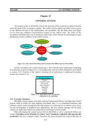
Horizontal Flux Density [ T ]<br />
0.8<br />
0.6<br />
0.4<br />
0.2<br />
0<br />
-120 -80 -40<br />
-0.2<br />
0 40 80 120<br />
-0.4<br />
-0.6<br />
x [ mm ]<br />
Figure 11. Transverse flux density of the vertical undulator phase at minimum gap.<br />
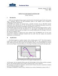
As mentioned in Section 3.3, the end block configuration is capable of reducing the first and second<br />
field integrals below the specified limits without using passive (shimming technique ) or active (trim<br />
coils) correction schemes at this stage of the design. Figure 12 shows the on-axis first field integral at<br />
minimum gap as a function of the undulator phase. The values are still less than 20% of the specified<br />
limit. Figure 13 shows the first field integral for the three modes of operation at minimum gap as a<br />
function of the transverse x-axis. The values for x = ±25mm are within 35% of the specified limit.<br />
15<br />
10<br />
First vert. integral [ G.cm ]<br />
5<br />
0<br />
-5<br />
-10<br />
-15<br />
-20<br />
0 5 10 15 20 25 30 35<br />
-25<br />
Undulator Phase [ mm ]<br />
Figure 12. On-axis first field integral of the <strong>SESAME</strong> EPU at minimum gap.<br />
8