Chapter 3 : Upgrading of BESSY I - SESAME
Chapter 3 : Upgrading of BESSY I - SESAME
Chapter 3 : Upgrading of BESSY I - SESAME

You also want an ePaper? Increase the reach of your titles
YUMPU automatically turns print PDFs into web optimized ePapers that Google loves.
3. <strong>Upgrading</strong> <strong>of</strong> <strong>BESSY</strong> I<br />
3.1 Introduction<br />
<strong>BESSY</strong> I is disassembled, very well packed, shipped from Berlin and has already been arrived<br />
in Jordan. The design <strong>of</strong> the building is very well advanced and the documents <strong>of</strong> the building for a<br />
call for tender process should be finished by the end <strong>of</strong> June. With the space in the experimental<br />
hall and the requirement <strong>of</strong> the users to have a length <strong>of</strong> the beam lines up to at least 30 m, the<br />
circumference <strong>of</strong> the storage ring should be smaller than 125m. The upgrading <strong>of</strong> <strong>BESSY</strong> I for<br />
<strong>SESAME</strong> is documented in the so-called “Green Book“, issued October 1999. From 1999 until now<br />
a lot <strong>of</strong> workshops concerning the scientific case at <strong>SESAME</strong> have been held and there exists a<br />
better understanding <strong>of</strong> what is needed in the “Middle East Region”. According to the report <strong>of</strong> H.<br />
Winick, the number <strong>of</strong> x-ray beamlines should be increased and also one should try to increase the<br />
performance <strong>of</strong> the machine. This has to be done within the existing budget boundaries. In the<br />
following report different versions for upgrading <strong>BESSY</strong> I are investigated and a new upgrading<br />
version is proposed.<br />
3.2 Performance <strong>of</strong> a Synchrotron Light source<br />
The performance <strong>of</strong> a synchrotron light source is given by three factors: 1) The spectral range<br />
covered by the synchrotron radiation. 2) The brilliance <strong>of</strong> the emitted light and 3) The number <strong>of</strong><br />
experimental stations.<br />
3.2.1 Spectral Range <strong>of</strong> the Synchrotron Radiation<br />
The spectral range <strong>of</strong> the synchrotron radiat critic),<br />
which is proportional to the square <strong>of</strong> the electron beam energy and proportional to the magnetic<br />
flux <strong>of</strong> the magnet. In order to reach the 20 keV range, it is foreseen in the “Green Book” to run the<br />
machine at 1 GeV and make the installation <strong>of</strong> up to three super conducting wigglers (7.5 Tesla).<br />
This leads to critical photon energy <strong>of</strong> 5 keV. The useable spectrum is extending to roughly four<br />
times the critical photon energy. The 20 keV range can also be covered with a 2 GeV beam and a<br />
magnetic flux density <strong>of</strong> 1.88 Tesla. The present technology allows construction <strong>of</strong> permanent<br />
magnet wigglers with flux density <strong>of</strong> 2.25 Tesla. A 2 GeV beam deflected in such a wiggler would<br />
cover a spectral range <strong>of</strong> up to 24 keV. The radiation from the bending magnet (“Green Book”<br />
Design, 1 GeV and 1.87 Tesla) covers a range up to 5 keV. That one <strong>of</strong> a 2 GeV beam deflected in a<br />
bending with 1.5 Tesla covers a range up to 16 keV. Because the spectrum range goes with the<br />
square <strong>of</strong> the energy it would be very worthwhile increasing it. But this process is limited, because<br />
the emittance (see next paragraph) is proportional to the square <strong>of</strong> the energy.<br />
3.2.2 Brilliance <strong>of</strong> the Radiation<br />
The brilliance is the figure <strong>of</strong> merit for the classification <strong>of</strong> the synchrotron radiation. At a<br />
synchrotron light source, the radiation with the highest brilliance comes from the undulators or<br />
wigglers. At a 2 GeV machine the required 20 keV photons can only be delivered from wigglers<br />
(see chapter 2), hence <strong>SESAME</strong> will be a wiggler-dominated machine. The brilliance <strong>of</strong> a wiggler<br />
is given by Bessel functions, the energy <strong>of</strong> the beam, number <strong>of</strong> wiggler periods, current and the<br />
inverse <strong>of</strong> the cross section <strong>of</strong> the beam. The cross section <strong>of</strong> the beam is proportional to the<br />
emittance <strong>of</strong> the machine and the betatron functions. In general the emittance goes with the third<br />
power <strong>of</strong> the bending magnet deflection angle and with the square <strong>of</strong> the energy. In order to get a<br />
high brilliance <strong>of</strong> the wiggler radiation, the emittance <strong>of</strong> the machine and the betatron functions at<br />
the location <strong>of</strong> the wigglers should be small. Synchrotron light sources dominated by undulators or<br />
wigglers and with a small emittance (smaller than 15 to 20 nmrad) are called 3 rd generation light<br />
14
sources. In order to increase the brilliance <strong>of</strong> the radiation in an upgrading process <strong>of</strong> <strong>BESSY</strong> I one<br />
should try to decrease the emittance <strong>of</strong> the machine.<br />
3.2.3 Number <strong>of</strong> Experimental Stations<br />
In general the number <strong>of</strong> experimental stations are given by the space in the experimental hall.<br />
In a 3 rd generation light source the number <strong>of</strong> experimental stations is proportional to the number <strong>of</strong><br />
available straight section for the installation <strong>of</strong> insertion devices (undulator and wigglers) and with<br />
a lower priority the number <strong>of</strong> bending magnets. In order to qualify this point one uses the<br />
percentage <strong>of</strong> the circumference that can be used for the installation <strong>of</strong> insertion devices.<br />
Furthermore as indicated in section 2.2 the length <strong>of</strong> insertion device sections should be long for<br />
increasing the brilliance. In an upgrading process <strong>of</strong> <strong>BESSY</strong> I one should try to increase the number<br />
and length <strong>of</strong> the straight sections.<br />
3.3 <strong>Upgrading</strong> Versions <strong>of</strong> <strong>BESSY</strong> I<br />
3.3.1 Green Book Proposal<br />
With the “Green Book” proposal, the energy <strong>of</strong> the <strong>BESSY</strong> I will be increased from 0.8 to 1<br />
GeV by changing the magnetic flux in the bending magnets from 1.5 to 1.87 Tesla. Decreasing the<br />
gap and modifying the pole pr<strong>of</strong>ile <strong>of</strong> the bending magnet can do this. To reach the required photon<br />
spectrum, up to three 7.5 Tesla super conducting wigglers can be installed. To increase the number<br />
<strong>of</strong> straight sections the lattice is changed from the TBA- to a DBA- optic, which results in a 6-fold<br />
symmetry (increasing the useable straights by a factor 2). To avoid the influence <strong>of</strong> the high field<br />
wiggler to the beam and to increase the brilliance <strong>of</strong> the radiation a so-called “mini beta section”<br />
has to be introduced at the position <strong>of</strong> the wigglers. The circumference <strong>of</strong> the machine will increase<br />
from 64 to roughly 100 m. The parameters <strong>of</strong> <strong>BESSY</strong> I, the upgraded version without (SES_1_1)<br />
and with a mini beta section (SES_1_2) are given in Table (3.1). The number <strong>of</strong> the existing<br />
magnets and the power supplies <strong>of</strong> <strong>BESSY</strong> I are compiled in Table (3.2).<br />
Table 3.1: Main parameters <strong>of</strong> <strong>BESSY</strong> I, the “Green Book Proposal” without (SES_1_1) and with a<br />
mini beta section (SES_1_2)<br />
Parameter <strong>BESSY</strong> I SES_1_1 SES_1_2<br />
Energy (GeV) 0.8 0.8 1.0<br />
Emittance (nmrad) 56.8 7.85 50 – 107<br />
Number <strong>of</strong> straights 4 6 6<br />
Useable wiggler straights and length (m) 2 / 2.60 4 / 4.80 3 / 2.00<br />
Useable undulator straights and length (m) 1 / 4.80<br />
Circumference (m) 64.0 100.8 100.8<br />
8.1 22.9 10.7<br />
x, bending / wiggler) (mm) 0.138/0.341 0.063/0.607 0.375/0.644<br />
y, bending / wiggler) (mm) 0.050/0.023 0.057/0.029 0.209/0.030<br />
x y)<br />
Bending magnet (mm^2) 0.044 0.023 0.493<br />
Wiggler / Undulator (mm^2) 0.049 0.111 0.121/0.619<br />
Critical photon energy<br />
Bending magnet (keV) 0.64 0.64 1.24<br />
Wiggler(2.25Tesla) (keV) 0.96 0.96 1.50<br />
Undulator<br />
(keV)<br />
Wavelength shifter (7.5Tesla) (keV) 3.0 3.0 5.0<br />
Noticeable are the increase <strong>of</strong> the emittance and the reduction <strong>of</strong> the length <strong>of</strong> the straights by<br />
the introducing <strong>of</strong> the mini beta section. Also from the cross section <strong>of</strong> the beam (area <strong>of</strong> the spot<br />
15
size) SES_1_2 can’t compete with <strong>BESSY</strong> I. The emittance depends upon the number <strong>of</strong> wigglers,<br />
according to the additional damping.<br />
For the version SES_1_1 all magnetic elements <strong>of</strong> <strong>BESSY</strong> I can be used and 8 additional<br />
sextupoles with a length <strong>of</strong> 0.15 m are required. For the version SES_1_2 the 12 bending magnets<br />
have to be modified, furthermore 8 additional quadrupoles and 8 sextupoles are needed.<br />
Table 3.2: Characteristic data <strong>of</strong> the <strong>BESSY</strong> I magnets and power supplies. In the column “Number” the<br />
first figure gives the number <strong>of</strong> power supplies and the second the number <strong>of</strong> magnets.<br />
Power Supply Number Data Data(mm) Voltage(V) Current(A) Power(kW)<br />
Bending magnet 1 / 12 1,5 T 60 gap 305 900 275.0<br />
Quadrupole Q0 4 / 28 11.5 T/m 100 bore 52 1025 213.0<br />
Quadrupole Q1 1 / 4 11.5 T/m 100 bore 30 1100 33<br />
Quadrupole Q2 1 / 4 14,5 T/m 100 bore 38 1400 53.2<br />
Sextupole Sh 1 / 8 557 T/m^2 120 bore 83 400 33.2<br />
Sextupole Sv 1 / 4 418 T/m^2 120 bore 63 300 18.9<br />
Corrector magnets 20 20 10 4.0<br />
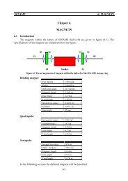
3.3.2 <strong>Upgrading</strong> <strong>of</strong> <strong>BESSY</strong> I to 2 GeV<br />
3.3.2.1 <strong>Upgrading</strong> to a 6 fold Symmetry and DBA-Lattice<br />
The energy <strong>of</strong> an accelerator is given by the integral <strong>of</strong> the magnetic flux around the ring. For<br />
the increase <strong>of</strong> the energy from 1 GeV to 2 GeV longer magnets must be installed. The easiest way<br />
is to keep the foreseen DBA-lattice in the Green-book-report and change the 12 bending magnets <strong>of</strong><br />
<strong>BESSY</strong> I with a deflection radius <strong>of</strong> 1.779 m by new ones with a radius <strong>of</strong> 4.4474 m (the<br />
corresponding magnetic flux is 1.5 Tesla). In this case one needs 12 new bending magnets and 8<br />
new sextupoles. This version is called SES_2_1; the parameters <strong>of</strong> this version are summarized in<br />
Table (3.3)<br />
As in paragraph 2 stressed, for a high brilliance one needs a small cross section <strong>of</strong> the beam.<br />
This can be done locally in a storage ring by introducing a so-called “mini beta section”. For doing<br />
this one has to introduce on each side <strong>of</strong> the straight section a quadrupole triplet instead <strong>of</strong> a<br />
doublet. This version is named SES_2_2; the parameters are summarized in Table (3.4).<br />
3.3.2.2 <strong>Upgrading</strong> to an 8-fold Symmetry and DBA-Lattice<br />
The emittance <strong>of</strong> the electron beam is proportional to the third power <strong>of</strong> the deflection angle<br />
<strong>of</strong> the bending magnets. Going from the 6-fold symmetry to 8 fold would decrease the emittance by<br />
a factor 2.4 and would increase the number <strong>of</strong> useable straight sections from 4 to 6. This version is<br />
called SES_3_1. Per cell there is the same arrangements <strong>of</strong> magnets (DBA-lattice) as for the version<br />
SES_2_1. The corresponding version with a mini beta section is named SES_3_2. The parameters<br />
<strong>of</strong> both versions are summarized in Table (3.3) and (3.4).<br />
3.3.2.3 <strong>Upgrading</strong> to an 8-fold Symmetry and a TME-lattice.<br />
Introducing combined magnets, for example gradient bending magnets, can reduce the<br />
number <strong>of</strong> magnets in an accelerator. In the past a lot <strong>of</strong> synchrotron light sources have been<br />
designed with gradient bending magnets (ALS, ELETTRA, CLS, SPEAR3 etc.). This design has<br />
further the advantage that the emittance will be reduced. Sometimes this lattice is called the<br />
“Theoretical Minimum Emittance”-lattice (TME-lattice). This version is called SES_4_1 and the<br />
parameters <strong>of</strong> this version are given in Table (3.3). For the version SES_4_1 all quadrupoles and<br />
sextupoles from <strong>BESSY</strong> I can be used. By the given maximum circumference <strong>of</strong> 125 m this limits<br />
the length <strong>of</strong> the straight sections.<br />
16
In an upgrading process the length <strong>of</strong> the quadrupoles and sextupoles can be changed in order<br />
to get longer straight sections. Furthermore a mini beta section can be introduced (version<br />
SES_4_2). The parameters <strong>of</strong> these versions are summarized in Table (3.3) and (3.4).<br />
Table 3.3: Main parameters <strong>of</strong> the versions upgraded to 2 GeV. SES_2_1 has 6 fold, SES_3_1 and<br />
SES_4_1 have 8-fold symmetry. SES_4_1 uses gradient bending magnets and <strong>BESSY</strong> I<br />
quads and sextupoles.<br />
Parameter SES_2_1 SES_3_1 SES_4_1<br />
Energy (GeV) 2.0 2.0 2.0<br />
Emittance (nmrad) 62.2 23.7 18.7<br />
Number <strong>of</strong> straights 6 8 16<br />
Useable wiggler straights and length (m) 4 / 4.64 6 / 3.20 8 / 2.43<br />
Useable undulator straights and length (m) 6 / 1.80<br />
Circumference (m) 112.0 116.0 120.0<br />
16.5 20.6 35.7<br />
x, bending / wiggler) (mm) 0.283/1.484 0.136/0.847 0.167/0.613<br />
y, bending / wiggler) (mm) 0.120/0.108 0.074/0.025 0.078/0.032<br />
x y)<br />
Bending magnet (mm^2) 0.214 0.063 0.082<br />
Wiggler/ Undulator (mm^2) 1.007 0.133 0.123/0.092<br />
Critical photon energy<br />
Bending magnet (keV) 4.00 4.00 3.60<br />
Wiggler (2.25Tesla) (keV) 6.00 6.00 6.00<br />
Undulator<br />
(keV)<br />
Wavelength shifter (7.5Tesla) (keV) 20.0 20.0 20.0<br />
Table 3.4: Main parameters <strong>of</strong> the versions upgraded to 2 GeV with a mini beta section. SES_2_2 has<br />
6 fold, SES_3_2 and SES_4_2 have 8-fold symmetry. SES_4_2 uses gradient bending<br />
magnets.<br />
Parameter SES_2_2 SES_3_2 SES_4_2<br />
Energy (GeV) 2.0 2.0 2.0<br />
Emittance (nmrad) 76.0 25.6 12.9<br />
Number <strong>of</strong> straights 6 8 16<br />
Useable wiggler straights and length (m) 3 / 3.84 4 / 3.20 8 / 2.60<br />
Useable undulator straights and length (m) 1 / 4.64 2 / 3.20 6 / 1.70<br />
Circumference (m) 116 122.0 124.0<br />
13.9 19.6 34.6<br />
x, bending / wiggler) (mm) 0.336/0.322 0.149/0.145 0.097/0.254<br />
y, bending / wiggler) (mm) 0.139/0.033 0.083/0.029 0.062/0.0073<br />
Beam size area (2* x y)<br />
Bending magnet (mm^2) 0.241 0.077 0.038<br />
Wiggler/Undulator (mm^2) 0.067/1.24 0.026/0.295 0.012/0.081<br />
Critical photon energy<br />
Bending magnet (keV) 4.0 4.0 3.6<br />
Wiggler (2.25Tesla) (keV) 6.0 6.0 6.0<br />
Undulator<br />
(keV)<br />
Wavelength shifter (7.5Tesla) (keV) 20 20 20<br />
3.4 Comparison <strong>of</strong> the Different Versions<br />
3.4.1 Magnets<br />
For the different upgrading versions the needed magnets are summarized in Table (3.5). To<br />
upgrade the storage ring to 1 GeV (version: SES_1_2) the bending magnets have to be modified in<br />
17
order to reach a field <strong>of</strong> 1.87 Tesla. Furthermore 8 quadrupoles and 8 sextupoles are needed. For<br />
this version a DBA lattice is foreseen and the symmetry <strong>of</strong> the machine is 6 fold.<br />
For a 2 GeV storage ring (version SES_2_1) 12 new bending magnets and 8 new sextupoles<br />
are needed. In order to increase the brilliance <strong>of</strong> the radiation from the wiggler a “mini beta section”<br />
should be introduced. This is possible with the version SES_2_2 for which 6 additional quadrupoles<br />
with a length <strong>of</strong> 0.7 m are requested.<br />
Table 3.5: Number <strong>of</strong> magnet elements needed for the different upgrading versions for <strong>SESAME</strong>. The lengths<br />
<strong>of</strong> the elements are given in brackets.<br />
*) This is a combined quadrupole / sextupole magnet<br />
Version Bendings Quadrupoles Sextupoles New bends New quads New sextup.<br />
16<br />
16 16 (0.23)<br />
<strong>BESSY</strong> I 12 32 (0.44) 16 (0.25)<br />
4 (0.25)<br />
SES_1_1 12 30 (0.44) 16 (0.25)<br />
8 (0.15) 8 (0.15)<br />
SES_1_2 12 30 (0.44) 16 (0.25) 12 modified<br />
(Green book)<br />
12 (0.25) 8 (0.15)<br />
8 (0.25) 8 (0.15)<br />
SES_2_1 12 30 (0.44) 16 (0.25) 12<br />
8 (0.15)<br />
8 (0.15)<br />
SES_2_2 12 30 (0.44) 16 (0.25) 12<br />
6 (0.70) 8 (0.15)<br />
6 (0.70) 8 (0.15)<br />
SES_3_1 16 32 (0.44) 16 (0.25) 16<br />
8 (0.25) 16 (0.15)<br />
8 (0.25) 16 (0.15)<br />
SES_3_2 16 32 (0.44) 16 (0.25) 16<br />
8 (0.22) 16 (0.15)<br />
8 (0.22) 16 (0.15)<br />
8 (0.60)<br />
8 (0.60)<br />
SES_4_1 16 32 (0.44) 16 (0.25)<br />
32 (0.20) *) 16-32 (0.20) *)<br />
16 (0.15)<br />
16 (0.15)<br />
SES_4_2 16 16 (0.23) 32 (0.15)<br />
32 (0.15)<br />
16 (0.45)<br />
16 (0.35)<br />
32 (0.20) *) 16 (0.45)<br />
16 (0.35)<br />
32 (0.20) *)<br />
For an eight fold symmetry (SE_3_1) 16 new bending magnets, 8 quadrupoles and 16<br />
sextupoles are needed. In order to get 4 mini beta sections in the storage ring (SES_3_2) 8 more<br />
quadrupoles with a length <strong>of</strong> 0.6 m are needed.<br />
The version SES_4_1 needs 16 new bending magnets, 16 sextupoles with a length <strong>of</strong> 0.15 (m)<br />
and 16 to 32 combined sextupole / quadrupole magnets. In order to increase the length <strong>of</strong> the<br />
straight sections it is possible to change on a later stage the <strong>BESSY</strong> quadrupoles and sextupoles by<br />
more compact magnets. Furthermore by introducing 16 new quadrupoles it is possible to make in<br />
each cell a mini-beta-section (version SES_4_2).<br />
3.4.2 Performance <strong>of</strong> the Different <strong>Upgrading</strong> Versions<br />
Performance <strong>of</strong> the radiation <strong>of</strong> a synchrotron light source is given by the brilliance <strong>of</strong> the<br />
beam, the spectral range <strong>of</strong> the radiation and the overall length (or the number) <strong>of</strong> insertion devices<br />
that can be installed. The spectral range is given by the so-called critical photon energy, which is<br />
proportional to the magnetic field and proportional to the square <strong>of</strong> the beam energy. Hence by<br />
changing the energy from 1 GeV to 2 GeV, the useable spectrum is a factor <strong>of</strong> 4 broader. As already<br />
discussed in chapter 2 the spectrum is broader by a factor <strong>of</strong> 10.<br />
To avoid a super-conducting wiggler has two more advantages: 1) The high field <strong>of</strong> the<br />
wiggler has a strong influence <strong>of</strong> the behavior <strong>of</strong> the beam. 2) The operation <strong>of</strong> a super-conducting<br />
wiggler needs a special knowledge, which at present is not available at <strong>SESAME</strong>. 3) The superconducting<br />
wiggler is much more expensive.<br />
18
According to these arguments it would be worthwhile changing the energy <strong>of</strong> <strong>SESAME</strong> from<br />
1 GeV to 2 GeV.<br />
For a comparison <strong>of</strong> the different versions the main parameters are summarized in Table (3.6)<br />
and (3.7). In Table (3.6) without and in Table (3.7) with a mini beta section.<br />
Table 3.6: Main parameters <strong>of</strong> the different upgrading versions <strong>of</strong> <strong>SESAME</strong> in comparison to <strong>BESSY</strong> I and the<br />
“Green book Proposal” (SES_1_2). These are the basic versions without any mini beta section. The<br />
column “Factor” gives the overall length <strong>of</strong> the straight section (foreseen for the installation <strong>of</strong> all<br />
wigglers and undulators) divided by the cross section <strong>of</strong> the beam and the period length (8-cm) <strong>of</strong> the<br />
insertion device.<br />
Version<br />
Energy<br />
Emittance<br />
Circumf.<br />
% Area<br />
Wiggler<br />
( mm^2)<br />
Area<br />
Undulat.<br />
(mm^2)<br />
Area<br />
Bend.<br />
(mm^2)<br />
Factor<br />
(GeV) (nmrad) (m)<br />
<strong>BESSY</strong> I 0.8 55.2 64.0 8.1 0.049 0.044 758<br />
SES_1_1 0.8 7.8 100.8 22.9 0.111 0.023 2162<br />
SES_1_2 1.0 50 –100 100.8 10.7 0.121 0.638 0.493 450<br />
SES_2_1 2.0 62.2 112.0 16.6 1.01 0.214 230<br />
SES_3_1 2.0 24.0 116.0 20.5 0.095 0.044 2526<br />
SES_4_1 2.0 18.7 120.0 33.0 0.123 0.092 0.082 3442<br />
3.4.2.1 Without a “Mini-Beta-Section”<br />
The version SES_4_1 has an emittance in the range <strong>of</strong> 13 to 19 nm rad, which is a factor 2 to<br />
3 smaller than version SES_1_2. This yields to an increase in the brilliance by a factor 4 to 8. The<br />
emittance scales with the energy squared. Hence the emittance <strong>of</strong> version 4 would drop down to<br />
around 5-nm rad, running with an energy <strong>of</strong> 1 GeV (as in version 1). The dependency <strong>of</strong> the<br />
emittance on the deflection angle <strong>of</strong> the bending magnets is given by the comparison <strong>of</strong> version 2<br />
and 3; see Table (3.6). Going from a 6-fold to an 8-fold symmetry the emittance decreases by a<br />
factor <strong>of</strong> 2.8<br />
The column “%” gives the percentage <strong>of</strong> the circumference, which is available for the<br />
installation <strong>of</strong> insertion devices (wigglers or undulators). At <strong>BESSY</strong> I and SES_1_2 (the “Green<br />
Book” proposal) roughly 10 percent <strong>of</strong> the circumference can be used for wigglers. For the version<br />
SES_2_1 roughly 16 %, for the versions SE_3_1 around 20 % and for the version SE_4_ over 30<br />
%. Hence moving over from version SES_1_2 to SES_4_1 a length <strong>of</strong> roughly 30 m is further<br />
available for the insertion devices. These are more arguments in favor <strong>of</strong> higher energies or another<br />
layout <strong>of</strong> the machine.<br />
Important for the brilliance is the cross section <strong>of</strong> the beam. In Table (3.6) these values are<br />
given for the position <strong>of</strong> the wigglers, the undulators and the bending magnets. For the versions<br />
SES_2_1, SES_3_1 and SES_4_1 the cross section <strong>of</strong> the beam within the bending magnets is<br />
smaller than that <strong>of</strong> version SES_1_2. For the wigglers and undulators, versions SES_3_1 and<br />
SES_4_1 have roughly the same cross section but for the version SES_2_1 it is at this position up to<br />
a factor 8 to 9 higher.<br />
In order to make a comparison <strong>of</strong> the different version a new column “Factor” is introduced in<br />
Table (3.6), which gives the overall length <strong>of</strong> the insertion devices divided by the period length and<br />
the cross section <strong>of</strong> the beam. The brilliance <strong>of</strong> the radiation is proportional to this factor. The<br />
version SES_1_2 (Green-Book-Proposal) has a factor <strong>of</strong> 450. This factor decreases by a factor 2 for<br />
the version SES_2_1 because <strong>of</strong> the large emittance. The version SES_3_1 with a factor <strong>of</strong> 2526<br />
has a performance, which is about 5 times higher than the version SES_1_2. The performance<br />
increases further more (factor 1.3) by moving over to version SES_4_1. The factor 1.3 is given by<br />
the ratio <strong>of</strong> the straight sections (8/6=1.33).<br />
19
3.4.2.1 With a “Mini-Beta-Section”<br />
As mentioned before, the brilliance <strong>of</strong> the radiation from a wiggler and a bending magnet is<br />
inversely proportional to the cross section <strong>of</strong> the beam within these devices. The cross section<br />
within the wigglers can be changed and minimized with the introduction <strong>of</strong> a “mini-beta-section”.<br />
The installation <strong>of</strong> this “mini-beta-section” can be made in a later stage as an upgrading process.<br />
The main parameters <strong>of</strong> the different upgrading versions with a mini-beta-section are summarized<br />
in Table (3.7). By moving over from version SES_1_2 to SES_3_1 and SES_4_1 the performance<br />
would be increased by a factor 5.6 to 7.6. Not included in this number is the broader spectrum (up<br />
to a factor 10).<br />
Table 3.7: Main parameters <strong>of</strong> the different upgrading version <strong>of</strong> <strong>SESAME</strong> with a “mini-beta-Section” in<br />
comparison to <strong>BESSY</strong> I and the “Green-Book-Proposal” (SES_1_2). The column “Factor” gives the<br />
length <strong>of</strong> the straight section (foreseen for the wigglers and undulators) divided by the cross section<br />
<strong>of</strong> the beam and the length <strong>of</strong> the insertion device.<br />
Version<br />
Energy<br />
Emittance<br />
Circumf.<br />
% Area<br />
Wiggler<br />
( mm^2)<br />
Area<br />
Undulat.<br />
(mm^2)<br />
Area<br />
Bend.<br />
(mm^2)<br />
Factor<br />
(GeV) (nm*rad) (m)<br />
<strong>BESSY</strong> I 0.8 55.2 64.0 8.1 0.049 0.044 758<br />
SES_1_2 1.0 50 –100 100.8 10.7 0.121 0.638 0.493 450<br />
SES_2_2 2.0 76.0 116.0 13.9 0.053 1.071 0.214 2757<br />
SES_3_2 2.0 26.0 122.0 19.6 0.026 0.295 0.077 6425<br />
SES_4_2 2.0 13.0 124.0 34.6 0.012 0.081 0.038 23240<br />
With the installation <strong>of</strong> the mini-beta-section, the performance will be increased very much:<br />
for the version SES_2_2 to 6, for the version SES_3_2 to 14 and for the version SES_4_2 to a<br />
factor 52.<br />
The versions SES_4_1 and SES_4_2 have the best performances. The version SES_4_2 is an<br />
upgrading <strong>of</strong> version SES_4_1, which can be performed in a later stage. But one has to start with<br />
the version SES_4_1 to make this opportunity possible.<br />
3.5 Main Parameters <strong>of</strong> the Versions SES_4_1 and SES_4_2<br />
The lattice <strong>of</strong> these two versions are given in the Figures (3.1) and (3.2). The main parameters<br />
<strong>of</strong> the versions SES_4_1 and SES_4_2 are given in Table (3.8). Version SES_4_1 is the proposed<br />
starting version and SES_4_2 is an upgrading version, which can be erected in a later stage.<br />
Figure 3.1: Lattice and machine functions <strong>of</strong> the version SES_4_1. This is the<br />
proposed upgraded version <strong>of</strong> <strong>BESSY</strong> I for <strong>SESAME</strong><br />
20
Figure 3.2: Lattice and machine functions <strong>of</strong> the version SES_4_2. This version is an upgraded<br />
version <strong>of</strong> SES_4_1. The upgrading can be performed in a later stage.<br />
Table 3.8: Main Parameters <strong>of</strong> the proposed upgraded version SES_4_1 and the final one SES_4_2<br />
Parameter SES_4_1 SES_4_2<br />
General Parameters<br />
Energy (GeV) 2.0 2.0<br />
Beam current (mA) 400 400<br />
Circumference (m) 124.8 124.8<br />
Natural emittance (nmrad) 18.7 12.9<br />
Coupling (%) 2.0 2.0<br />
Horizontal emittance (nmrad) 18.4 12.65<br />
Vertical emittance (nmrad) 0.37 0.253<br />
Horizontal working point 6.79 9.20<br />
Vertical working point 4.72 6.28<br />
Momentum compaction factor 0.0090 0.0061<br />
Relative energy spread (%) 0.091 0.088<br />
Chromaticity (horizontal) -9.6 -26.6<br />
Chromaticity (vertical) -12.1 -21.7<br />
Machine functions<br />
Horizontal beta functions<br />
Wiggler / bending / undulator (m/rad) 8.42/0.70/8.24 2.30/0.32/11.9<br />
Vertical beta functions<br />
Wiggler / bending / undulator (m/rad) 2.78/16.5/1.55 0.21/15.1/2.57<br />
Dispersion function<br />
Wiggler / bending / undulator (m) 0.51/0.13/0.51 0.21/0.08/0.35<br />
Beam sizes and cross sections<br />
¢¡ £¤£¦¥ §©¨¦§©¡ £¦¥ <br />
¨<br />
£¤£¦¥ §©¨¦§©¡ ¨ ¢¡ £¦¥ <br />
Horizontal beam size<br />
613/167/610 254/97/495<br />
Vertical beam size<br />
32 / 78 / 24 7.3 / 25 / 62<br />
Cross section<br />
Wiggler / bending / undulator (mm^2) 0.123/0.082/0.092 0.012/0.038/0.081<br />
R.F-System<br />
Energy loss per turn (bending) (keV) 286.4 286.4<br />
Energy loss per turn (wiggler) (keV) 2*25.7= 51.4 8* 25.7= 205.6<br />
R.F.-frequency (MHz) 499.654 499.654<br />
Harmonic number 208 208<br />
R.F.-power (kW) 250 500<br />
Number <strong>of</strong> cavities 2 4<br />
Shunt impedance per c 3.6 3.6<br />
R.F.-cavity voltage (kV) 576 681<br />
Overvoltage factor 3.4 5.5<br />
Energy acceptance (%) 1.13 1.8<br />
Bunch length (mm) 12.1 7.0<br />
21
3.6 Characteristics <strong>of</strong> the Radiation from the Different Versions<br />
The real advantage or disadvantage <strong>of</strong> the different versions is given by a comparison <strong>of</strong> the<br />
performances <strong>of</strong> the synchrotron radiation emitted from the bendings and wigglers. This will be<br />
performed in the next subsections.<br />
3.6.1 Characteristics <strong>of</strong> the Radiation from the Bending Magnets<br />
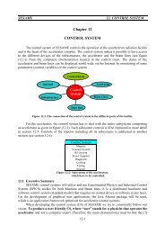
The flux, flux density and brilliance <strong>of</strong> the emitted radiation from the bendings <strong>of</strong> the<br />
discussed versions are presented in the Figures (3.3) to (3.8). Figure (3.4) gives the vertical opening<br />
angle <strong>of</strong> the radiation from a 1 GeV and 2 GeV beam.<br />
The fluxes emitted from a stored beam in a 1 GeV/1.87Tesla and 2 GeV/1.35Tesla storage<br />
ring are presented in Figure (3.3). According to the higher energy, the flux emitted from a 2 GeV<br />
machine is a factor <strong>of</strong> 2 higher. The critical photon energies <strong>of</strong> the c= 1.24 for the<br />
(1GeV/1.87T) version and 3.59 KeV for the (2GeV/1.35T) version. The spectrum for the 2 GeV<br />
storage ring is at least a factor 5 broader, although the critical photon energy <strong>of</strong> the machines differ<br />
only by a factor 3.<br />
Most <strong>of</strong> the users are more interested in the flux density, which gives the number <strong>of</strong> photons<br />
per second and sample area. The flux densities are presented in the Figures (3.5) and (3.6). The<br />
spectrum is the same as for the flux. According to the different emittances the flux density increases<br />
with the number <strong>of</strong> cells in the machine. There isn’t any large difference between the versions<br />
SE_4_1 and SE_3_1. The flux density <strong>of</strong> these two versions is however two orders <strong>of</strong> magnitudes<br />
higher than that for the version SE_1_2. Furthermore the spectrum is one order <strong>of</strong> magnitude<br />
broader. Overall we have a gain by moving over from version SE_1_2 to SE_3_1 or SE_4_1 by<br />
three orders <strong>of</strong> magnitude. There isn’t any big change by moving over to the mini beta versions<br />
(SE_3_2 or SE_4_2)<br />
1E+14<br />
Bending Flux<br />
SE_4_2 SE_1_1 SE_2_1<br />
Photons / second<br />
1E+13<br />
1E+12<br />
0.001 0.01 0.1 1 10 100<br />
Energy [keV]<br />
Figure 3.3: Flux <strong>of</strong> the synchrotron radiation from the bending magnets. Version<br />
SES_1_1: Green book, 1GeV, 1.87 Tesla, 400 mA; version SES_2_1:<br />
2GeV, 1.5 Tesla, 400 mA; version SES_4_2: 2GeV, 1.35 Tesla, 400 mA<br />
22
Radiation Opening Angle<br />
SE_1_2<br />
SE_3_1<br />
Angle [mrad]<br />
3<br />
2.5<br />
2<br />
1.5<br />
1<br />
0.5<br />
0<br />
0.01 0.1 1 10 100<br />
Photon energy [keV]<br />
Figure 3.4: Opening angle <strong>of</strong> the synchrotron radiation from the bending magnets<br />
with an energy <strong>of</strong> 1GeV (SES_1_2) and 2GeV (SES_3_1)<br />
1E+15<br />
Bending Flux Density<br />
SE_1_2 SE_3_1 Se_2_1 SE_4_1<br />
Photons / s mm^2<br />
1E+14<br />
1E+13<br />
1E+12<br />
0.01 0.1 1 10 100<br />
Photon energy [keV]<br />
Figure 3.5: Flux density <strong>of</strong> the synchrotron radiation from the bending magnets for<br />
versions: SES_1_2 (1GeV, 6 fold), SES_2_1 (2GeV, 8 fold), SES_3_1<br />
(2GeV, 8 fold ) and SES_4_1 (2GeV, 8 fold)<br />
23
Bending Flux Density<br />
SE_1_2 SE_3_2 SE_2_2 SE_4_2<br />
1E+15<br />
Phot/s*mm^2*0.1BW<br />
1E+14<br />
1E+13<br />
1E+12<br />
0.01 0.1 1 10 100<br />
Photon Energy [keV]<br />
Figure 3.6: Flux density <strong>of</strong> the synchrotron radiation from the bending magnets for versions:<br />
SES_1_2 (1GeV, 6 fold), SES_2_2 (2GeV, 8 fold), SES_3_2 (2GeV, 8 fold ) and<br />
SES_4_2 (2GeV, 8 fold)<br />
Bending Brilliance<br />
Photons/s*mm^2*mrad^2*B<br />
w<br />
1E+15<br />
1E+14<br />
1E+13<br />
1E+12<br />
SE_1_2 SE_3_1 SE_2_1 SE_4_1<br />
0.01 0.1 1 10 100<br />
Photon Energy [keV<br />
Figure 3.7: Brilliance <strong>of</strong> the synchrotron radiation from the bending magnets for the<br />
versions SES_1_2, SES_3_1, SES_2_1 and SES_4_1<br />
24
Bending Brilliance<br />
SE_1_2 SE_3_2 SE_2_2 SE_4_2<br />
1E+15<br />
Phot/s*mm^2*mrad^2*0.1BW<br />
1E+14<br />
1E+13<br />
1E+12<br />
1E+11<br />
0.01 0.1 1 10 100<br />
Photon Energy [keV]<br />
Figure 3.8: Brilliance <strong>of</strong> the synchrotron radiation from the bending magnets for the versions<br />
SES_1_2, SES_3_2, SES_2_2 and SES_4_2.<br />
The brilliances <strong>of</strong> the 1 and 2 GeV beams (400 mA) are given in the Figures (3.7) and (3.8).<br />
The critical photon energies <strong>of</strong> the different versions are: SE_1_I = 1.24 keV, SE_2_I = 4.00 keV,<br />
SE_3_I = 4.00 keV and SE_4_I = 3.60 keV. From the figures it follows that the maximum<br />
brilliance is around the critical photon energy. Because <strong>of</strong> the higher energy the brilliance <strong>of</strong> the 2<br />
GeV beam is one order <strong>of</strong> magnitude broader than for a 1 GeV beam. According to the smaller<br />
cross sections (emittances) the brilliances <strong>of</strong> the versions SE_3_I and SE_4_I are <strong>of</strong> a factor up to<br />
50 higher than from the 1 GeV beam (version SE_1_I). Also for the brilliance we gain a factor up to<br />
500 by moving over to the versions SE_3_1 or Se_4_1.<br />
3.6.2 Characteristics <strong>of</strong> the Radiation from the Wigglers<br />
The photon flux as well as the central intensity <strong>of</strong> the radiation emitted by the wiggler is the<br />
same as from the bending magnet but by a factor N p more intensive, where N p is the number <strong>of</strong><br />
poles within the wiggler. The photon flux emitted from the wigglers beams for the “Green Book”<br />
and this “Proposal” are presented in the Figures (3.9) and (3.12). Both wigglers have roughly the<br />
same critical photon energy ( c c(Proposal) = 6.0 keV) and therefore the<br />
spectrum <strong>of</strong> the flux is roughly the same.<br />
For the intensity <strong>of</strong> the photon flux the amplitudes X 0 <strong>of</strong> the beam oscillations within the<br />
wigglers have to be considered (see Table (2.1)). Because <strong>of</strong> the amplitude <strong>of</strong> 1.1mm in the “Green<br />
Book” design the spot sizes in the wigglers have a difference <strong>of</strong> 2.2 mm and it is not possible to<br />
collect both sources within one beam line. Therefore the useable flux from the wiggler for an<br />
experiment is only proportional to half <strong>of</strong> the number <strong>of</strong> the poles for the “Green Book” design. For<br />
the wiggler in this “Proposal” with an ampl <br />
have to be considered. All these arguments are included in the Figure (3.9) and (3.12), with the<br />
25
esult that the flux from the 2 GeV stored beam is <strong>of</strong> a factor 18 higher than that from the 1 GeV<br />
one.<br />
The flux density <strong>of</strong> the wiggler radiation is given in the Figures (3.10) and (3.13) (with minibeta-section).<br />
In these cases the spectrum is the same as for the flux, but with a different ratio <strong>of</strong> the<br />
intensities. Without a mini-beta-section the intensity <strong>of</strong> the flux density is a factor 18 higher and<br />
with a mini-beta-section it is a factor 200 higher. This already shows how important the<br />
introduction <strong>of</strong> a mini-beta-section is.<br />
The brilliance <strong>of</strong> the radiation emitted from the wigglers within the “Green Book” and this<br />
“Proposal” are presented in the Figures (3.11) and (3.14). Figure (3.14) is that one with the “minibeta-sections”.<br />
Again, because <strong>of</strong> the same critical photon energies the emitted spectrum covers the<br />
same range, because <strong>of</strong> the different cross sections <strong>of</strong> the beam the intensity is however different.<br />
For the versions SE_3_1 and SE_4_1 the intensity is roughly the same, but in comparison to<br />
version SE-1_2 they have a factor 35 higher intensity. The version SE_2_1 is <strong>of</strong> a factor 5 more<br />
intensive. The picture changes completely by introducing “mini-beta-sections”. The brilliance <strong>of</strong> the<br />
wiggler radiation for this version is presented in Figure (3.14), with the result that the brilliance <strong>of</strong><br />
the version SE_4_2 is <strong>of</strong> a factor 350 higher than that <strong>of</strong> the version SE_1_2.<br />
1E+16<br />
Wiggler Flux<br />
SE_1_2 SE_2_1 SE_4_1<br />
1E+15<br />
Phot./ s<br />
1E+14<br />
1E+13<br />
1E+12<br />
0.01 0.1 1 10 100<br />
Photon Energy [keV]<br />
Figure 3.9: Flux <strong>of</strong> the synchrotron radiation from the wiggler for the versions: SES_1_2,<br />
SES_2_1 and SES_4_1. As shown, the flux <strong>of</strong> the versions SES_2_1 and SES_4_1<br />
are the same because <strong>of</strong> the same specifications.<br />
26
Wiggler Flux Density<br />
SE_1_2 SE_2_1 SE_4_1 SE_3_1<br />
1E+17<br />
Phot./ s*mm^2*0.1BW<br />
1E+16<br />
1E+15<br />
1E+14<br />
1E+13<br />
0.01 0.1 1 10 100<br />
Photon Energy [keV]<br />
Figure 3.10: Flux density <strong>of</strong> synchrotron radiation from the wigglers <strong>of</strong> the versions SES_1_2,<br />
SES_2_1, SES_4_1 and SES_3_1<br />
Wiggler Brilliance<br />
SE_1_2 SE_2_1 SE_4_1 SE_3_1<br />
1E+17<br />
Phot./ s*mm^2*0.1BW<br />
1E+16<br />
1E+15<br />
1E+14<br />
1E+13<br />
0.01 0.1 1 10 100<br />
Photon Energy [keV]<br />
Figure 3.11: Brilliance <strong>of</strong> synchrotron radiation from the wigglers <strong>of</strong> the versions SES_1_2,<br />
SES_2_1, SES_4_1 and SES_3_1<br />
27
Wiggler Flux<br />
SE_1_2 SE_2_2 SE_4_2<br />
1E+16<br />
1E+15<br />
Phot./ s<br />
1E+14<br />
1E+13<br />
1E+12<br />
0.01 0.1 1 10 100<br />
Photon Energy [keV]<br />
Figure 3.12: Flux <strong>of</strong> the synchrotron radiation from the wiggler for the versions: SES_1_2,<br />
SES_2_2 and SES_4_2. As shown the flux <strong>of</strong> versions SES_2_2 and SES_4_2 are<br />
the same because <strong>of</strong> the same specifications.<br />
Wiggler Flux Density<br />
SE_1_2 SE_2_2 SE_4_2 SE_3_2<br />
1E+18<br />
Phot./ s*mm^2*0.1BW<br />
1E+17<br />
1E+16<br />
1E+15<br />
1E+14<br />
1E+13<br />
0.01 0.1 1 10 100<br />
Photon Energy [keV]<br />
Figure 3.13: Flux density <strong>of</strong> synchrotron radiation from the wigglers <strong>of</strong> the versions SES_1_2,<br />
SES_2_2, SES_4_2 and SES_3_2<br />
28
Wiggler Brilliance<br />
SE_1_2 SE_2_2 SE_4_2 SE_3_2<br />
1E+18<br />
Phot./ s*mm^2*0.1BW<br />
1E+17<br />
1E+16<br />
1E+15<br />
1E+14<br />
1E+13<br />
0.01 0.1 1 10 100<br />
Photon Energy [keV]<br />
Figure 3.14: Brilliance <strong>of</strong> synchrotron radiation from the wigglers <strong>of</strong> the versions SES_1_2,<br />
SES_2_2, SES_4_2 and SES_3_2<br />
29