Technical Note Amman, October 29, 2006 (draft) Note: M ... - SESAME
Technical Note Amman, October 29, 2006 (draft) Note: M ... - SESAME
Technical Note Amman, October 29, 2006 (draft) Note: M ... - SESAME

Create successful ePaper yourself
Turn your PDF publications into a flip-book with our unique Google optimized e-Paper software.
<strong>Technical</strong> <strong>Note</strong><br />
__________________________________________________________________________________________________<br />
<strong>Amman</strong>, <strong>October</strong> <strong>29</strong>, <strong>2006</strong><br />
(<strong>draft</strong>) <strong>Note</strong>: M-04<br />
Design Study of an Elliptically Polarizing Undulator for <strong>SESAME</strong><br />
Hamed Tarawneh<br />
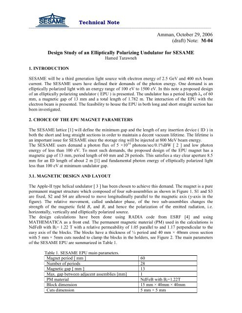
1. INTRODUCTION<br />
<strong>SESAME</strong> will be a third generation light source with electron energy of 2.5 GeV and 400 mA beam<br />
current. The <strong>SESAME</strong> users have defined their demands of the photon energy. One demand is an<br />
elliptically polarized light with an energy range of 100 eV to 1500 eV. In this note a proposed design<br />
of an elliptically polarizing undulator ( EPU ) is presented. The undulator has a period length u of 60<br />
mm, a magnetic gap of 13 mm and a total length of 1.782 m. The interaction of the EPU with the<br />
electron beam is presented. The feasibility to house the EPU in both long and short straight section has<br />
been investigated.<br />
2. CHOICE OF THE EPU MAGNET PARAMETERS<br />
The <strong>SESAME</strong> lattice [1] will define the minimum gap and the length of any insertion device ( ID ) in<br />
both the short and long straight sections in order to maintain a decent vacuum lifetime. The lifetime is<br />
an important issue for <strong>SESAME</strong> since the storage ring will be injected at 800 MeV beam energy.<br />
The <strong>SESAME</strong> users demand a photon flux of 5 ×10 14 photons/sec/0.1%BW [ 2 ] and low photon<br />
energy of less than 100 eV. To meet such demands, the proposed design of the EPU magnet has a<br />
magnetic gap of 13 mm, period length of 60 mm and 28 periods. This satisfies a stay clear aperture 8.5<br />
mm for an ID length of about 2 m [1] and fundamental photon energy of elliptically polarized light<br />
less than 100 eV at minimum undulator gap.<br />
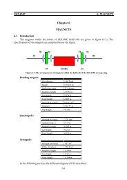
3.1. MAGNETIC DESIGN AND LAYOUT<br />
The Apple-II type helical undulator [ 3 ] has been chosen to achieve this demand. The magnet is a pure<br />
permanent magnet structure which composed of four sub-assemblies as shown in Figure 1. S1 and S3<br />
are fixed, S2 and S4 are allowed to move longitudinally parallel to the magnetic axis (y-axis in the<br />
figure). The relative movement, called undulator phase, of the two sub-assemblies changes the<br />
strength of the magnetic field B x and B z and hence the polarization of the emitted radiation, i.e.<br />
horizontally, vertically and elliptically polarized source.<br />
The design calculations have been done using RADIA code from ESRF [4] and using<br />
MATHEMATICA as a front end. The permanent magnetic material (PM) used in the calculations is<br />
NdFeB with B r = 1.22 T with a relative permeability of 1.05 parallel to and 1.17 perpendicular to the<br />
easy axis of the blocks. The blocks have a thickness of ¼ period and 40 mm × 40mm cross section<br />
with 5 mm × 5mm cuts needed to clamp the blocks in the holders, see Figure 2. The main parameters<br />
of the <strong>SESAME</strong> EPU are summarized in Table 1.<br />
Table 1. <strong>SESAME</strong> EPU main parameters.<br />
Magnet period [ mm ] 60<br />
Number of periods 28<br />
Magnetic gap [ mm ] 13<br />
Max. gap between adjacent assemblies [mm] 1<br />
PM material<br />
NdFeB with B r =1.22T<br />
Block dimension<br />
15 mm × 40mm × 40mm<br />
Cuts dimension<br />
5 mm × 5 mm
S1<br />
S2<br />
z<br />
S4<br />
S3<br />
x<br />
y<br />
Figure 1. Four sub-assemblies schematic of <strong>SESAME</strong> EPU.<br />
3.2. MODES OF OPERATIONS<br />
Figure 2. One permanent magnetic material block.<br />
Three modes of operation are foreseen for this magnet;<br />
1. Horizontally polarized mode: an undulator phase of 0 mm.<br />
2. Vertically polarized mode: an undulator phase of u /2 mm.<br />
3. Elliptically polarized mode: an undulator phase between 0 mm and u /2 mm.<br />
2
The inclined mode of operation has not been considered for this magnet. The inclined polarized light is<br />
achieved by moving the assemblies S2 and S4 longitudinally but opposing each other.<br />
3.3. END BLOCKS CONFIGURATION<br />
It is important that there is no net change in angle or transverse position on the electron beam in the<br />
EPU undulator, i.e. zero first and second field integrals [5, 6]. This effect, determined by the non-unit<br />
permeability of the PM material, can be significantly minimized by the design of the end blocks of the<br />
magnet [7, 8]. The Elettra scheme has been used for the <strong>SESAME</strong> EPU which makes use of halfthickness<br />
( u /8) blocks with spaces (A1, A2, A3) that are numerically optimized to reduce the field<br />
integrals [8], see Figure 3. The length of the full-size magnet is 1.752 m and by adding half a period<br />
length for the longitudinal translation of the two sub-assemblies, a total length of 1.782 m needed to<br />
house this magnet.<br />
Figure 3. End blocks configuration for <strong>SESAME</strong> EPU.<br />
The criteria specifications on the field integrals for the <strong>SESAME</strong> EPU are as below;<br />
First Integral: ∫ B<br />
, z<br />
( x z = 0)<br />
Second Integral: ∫∫ B x z<br />
( x = z = )<br />
3.4. FLUX DENSITIES AND FIELD INTEGRALS<br />
= dy ≤ 100G<br />
cm<br />
x<br />
.<br />
'<br />
5<br />
,<br />
0 dy dy ≤10<br />
G.<br />
cm<br />
An asymmetric layout has been adopted for the <strong>SESAME</strong> EPU, i.e. the vertical field has the same<br />
polarities at the entrance and exit of the magnet. The magnetic flux densities B x (horizontal) and B z<br />
(vertical) for an EPU device can be written as follows<br />
2<br />
Where φ<br />
B<br />
φ 2π<br />
φ<br />
0,0, s)<br />
= Bz<br />
.cos( ).sin( y + )<br />
2 λ 2<br />
z<br />
(<br />
0<br />
φ 2π<br />
φ<br />
Bx<br />
( 0,0, s)<br />
= −Bx0.sin(<br />
).cos( y + )<br />
2 λu<br />
2<br />
∆y<br />
φ = 2π<br />
λ<br />
u<br />
u<br />
is the undulator phase and y is the longitudinal translation of the assemblies in meter.<br />
3
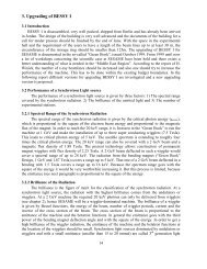
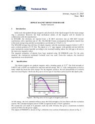
The magnetic flux density on-axis for the three modes of operations as a function of undulator gap<br />
and phase are shown in Figures 4. The fundamental photon energies are shown in Figure 5. Table 2<br />
summarizes the main magnetic properties of the <strong>SESAME</strong> EPU at minimum gap.<br />
1.2<br />
Magnetic Flux Density [Tesla]<br />
1<br />
0.8<br />
0.6<br />
0.4<br />
0.2<br />
gap= 13mm<br />
gap= 16mm<br />
gap= 20mm<br />
gap= 30mm<br />
gap= 50mm<br />
gap= 75mm<br />
gap=100mm<br />
0<br />
0 5 10 15 20 25 30 35<br />
Undulator Phase [mm]<br />
Figure 4. On-axis magnetic flux densities of the <strong>SESAME</strong> EPU.<br />
Fundamental Photon Energy [eV]<br />
1200<br />
1000<br />
800<br />
600<br />
400<br />
200<br />
0<br />
0 10 20 30 40<br />
Undulator Phase [mm]<br />
Figure 5. Fundamental photon energies of the <strong>SESAME</strong> EPU.<br />
gap= 13mm<br />
gap= 16mm<br />
gap= 20mm<br />
gap= 30mm<br />
gap= 50mm<br />
gap= 75mm<br />
gap=100mm<br />
4
Table 2. Flux densities, k-values and minimum photon energies at minimum gap of 13mm.<br />
Undulator<br />
Phase<br />
Horizontal Flux<br />
Density (T)<br />
Vertical Flux<br />
Density (T)<br />
k-value Photon Energy<br />
(eV)<br />
Horizontal<br />
- 0.9724 5.44 62<br />
0 mm<br />
Circular 0.60 0.60 3.36 79<br />
17.2 mm<br />
Vertical<br />
30 mm<br />
0.7617 - 4.26 98<br />
The magnetic flux densities, both longitudinal and transverse, for a 10-periods model at minimum gap<br />
of 13 mm for the three modes of operation are shown in Figures 6 to 11. The dip at x=0 in Figure 7 is<br />
due to the 1 mm separation distance between the left and the right assemblies of the magnet. This<br />
effect, called transverse roll off, will result in different flux densities seen by the electron far out from<br />
the centre of the transverse phase space. This focusing effect leads to an angular kick of the off-centre<br />
electron and, hence, reduces the dynamic aperture of the storage ring, see Section 4.3. The transverse<br />
roll off becomes very strong for the vertical mode of operation as shown in Figure 11.<br />
1.5<br />
1<br />
Flux Density [ T ]<br />
0.5<br />
0<br />
-500 -300 -100 100 300 500<br />
-0.5<br />
-1<br />
-1.5<br />
Longitudinal position [ mm ]<br />
Figure 6. Longitudinal flux density for the horizontal undulator phase at minimum gap.<br />
5
Transverse Flux Density [ T ]<br />
1.2<br />
1<br />
0.8<br />
0.6<br />
0.4<br />
0.2<br />
0<br />
-100 -50 0 50 100<br />
x [ mm ]<br />
Figure 7. Transverse flux density of the horizontal undulator phase at minimum gap.<br />
0.8<br />
0.6<br />
Bx<br />
Bz<br />
0.4<br />
Flux Density [ T ]<br />
0.2<br />
0<br />
-500 -300 -100 100 300 500<br />
-0.2<br />
-0.4<br />
-0.6<br />
-0.8<br />
Longitudinal position [ mm ]<br />
Figure 8. Longitudinal flux density for the circular undulator phase at minimum gap.<br />
6
Flux Density [ T ]<br />
0.7<br />
0.6<br />
0.5<br />
0.4<br />
0.3<br />
0.2<br />
0.1<br />
0<br />
-150 -100 -50 -0.1 0 50 100 150<br />
-0.2<br />
-0.3<br />
-0.4<br />
x [ mm ]<br />
Bx<br />
Bz<br />
Figure 9. Transverse flux density of the circular undulator phase at minimum gap.<br />
1<br />
0.8<br />
0.6<br />
Bx<br />
Bz<br />
Flux Density [ T ]<br />
0.4<br />
0.2<br />
0<br />
-500 -300 -100<br />
-0.2<br />
100 300 500<br />
-0.4<br />
-0.6<br />
-0.8<br />
-1<br />
Longitudinal position [ mm ]<br />
Figure 10. Longitudinal flux density for the vertical undulator phase at minimum gap.<br />
7
1<br />
Horizontal Flux Density [ T ]<br />
0.8<br />
0.6<br />
0.4<br />
0.2<br />
0<br />
-120 -80 -40<br />
-0.2<br />
0 40 80 120<br />
-0.4<br />
-0.6<br />
x [ mm ]<br />
Figure 11. Transverse flux density of the vertical undulator phase at minimum gap.<br />
As mentioned in Section 3.3, the end block configuration is capable of reducing the first and second<br />
field integrals below the specified limits without using passive (shimming technique ) or active (trim<br />
coils) correction schemes at this stage of the design. Figure 12 shows the on-axis first field integral at<br />
minimum gap as a function of the undulator phase. The values are still less than 20% of the specified<br />
limit. Figure 13 shows the first field integral for the three modes of operation at minimum gap as a<br />
function of the transverse x-axis. The values for x = ±25mm are within 35% of the specified limit.<br />
15<br />
10<br />
First vert. integral [ G.cm ]<br />
5<br />
0<br />
-5<br />
-10<br />
-15<br />
-20<br />
0 5 10 15 20 25 30 35<br />
-25<br />
Undulator Phase [ mm ]<br />
Figure 12. On-axis first field integral of the <strong>SESAME</strong> EPU at minimum gap.<br />
8
First vert. integral [ G.cm ]<br />
100<br />
80<br />
60<br />
40<br />
20<br />
0<br />
-30 -20 -10 0 10 20 30<br />
-20<br />
-40<br />
-60<br />
-80<br />
-100<br />
x [ mm ]<br />
Phase = 0 mm<br />
Phase =10 mm<br />
Phase =17.2mm<br />
Phase =23mm<br />
Phase = 30mm<br />
Figure 13. First field integral as function of x-axis at minimum gap.<br />
Figures 14 to 19 show the electron beam orbit, both longitudinal and projected on the xz-plane,<br />
through the 10-periods model magnet. We could see that the maximum orbit offset inside the EPU is<br />
about 24 m horizontally for the planar mode and -3 m vertically for the vertical mode. The second<br />
integral of the full size magnet can be extrapolated from the model. The results for the second field<br />
integrals and the beam position at the magnet exit are shown in Table 3. All values of the second<br />
integrals are within the specified limits, expect for the case of B z for the planar mode of operation.<br />
This can be easily reduced by using a long correction (trim) coils with vertical field.<br />
Table 3. The second integrals and beam position at the exit of the <strong>SESAME</strong> EPU.<br />
Phase B x .dy’dy<br />
[G.cm 2 ]<br />
Beam<br />
Position [m]<br />
B z .dy’dy<br />
[G.cm 2 ]<br />
Beam<br />
Position [m]<br />
Horizontal 0 0 10640 12.72<br />
Circular 520 0.62 7280 8.74<br />
Vertical <strong>29</strong>96 3.60 5392 6.47<br />
9
40<br />
35<br />
30<br />
Hor. Traj.<br />
Ave. Hor. traj.<br />
Trajectory [ micrometer ]<br />
25<br />
20<br />
15<br />
10<br />
5<br />
0<br />
-500 -300 -100<br />
-5<br />
100 300 500<br />
-10<br />
y [ mm ]<br />
Figure 14. The 2.5 GeV electron trajectory in the model magnet for the horizontal undulator phase.<br />
0.E+00<br />
-40 -35 -30 -25 -20 -15 -10 -5 0 5<br />
-1.E-06<br />
-2.E-06<br />
z [ micrometer ]<br />
-3.E-06<br />
-4.E-06<br />
-5.E-06<br />
-6.E-06<br />
x [ micrometer ]<br />
-7.E-06<br />
Figure 15. The 2.5 GeV electron trajectory in the xz-plane for the horizontal undulator phase.<br />
10
Trajectory [ micrometer ]<br />
55<br />
45<br />
35<br />
25<br />
15<br />
5<br />
Hor. Trajectory<br />
Aver. Hor. Trajectory<br />
Vert. Trajectory<br />
Aver. Vert. Trajectory<br />
-500 -300 -100 -5 100 300 500<br />
-15<br />
y [ mm ]<br />
Figure 16. The 2.5 GeV electron trajectory in the model magnet for the circular undulator phase.<br />
z [ micrometer ]<br />
10<br />
8<br />
6<br />
4<br />
2<br />
0<br />
-35 -30 -25 -20 -15 -10 -5 0<br />
-2<br />
5<br />
-4<br />
-6<br />
-8<br />
x [ micrometer ]<br />
-10<br />
Figure 17. The 2.5 GeV electron trajectory in the xz-plane for the circular undulator phase.<br />
11
Trajectory [ micrometer ]<br />
30<br />
Hor. Trajectory<br />
25<br />
Ave. Hor. Traj.<br />
Vert. Trajectory<br />
20<br />
Ave. Vert. Traj.<br />
15<br />
10<br />
5<br />
0<br />
-600 -400 -200 0 200 400 600<br />
-5<br />
-10<br />
-15<br />
y [ mm ]<br />
Figure 18. The 2.5 GeV electron trajectory in the model magnet for the vertical undulator phase.<br />
10<br />
5<br />
z [ micrometer ]<br />
-30 -25 -20 -15 -10 -5 0<br />
0<br />
-5<br />
-10<br />
x [ micrometer ]<br />
-15<br />
Figure 19. The 2.5 GeV electron trajectory in the xz-plane for the vertical undulator phase.<br />
12
4. INTERACTION BETWEEN EPU AND ELECTRON BEAM<br />
4.1. FOCUSING POTENTAIL<br />
The transverse roll off of the magnetic flux results in an angular kicks and, hence a tune shift. This is<br />
expressed by a focusing potential given by [7, 9];<br />
∞<br />
2<br />
1 e<br />
' ' 2<br />
' ' 2<br />
Φ(<br />
x , z)<br />
= − ( ) ∫((<br />
∫Bx<br />
( x,<br />
z,<br />
y ) dy ) + ( ∫Bz<br />
( x,<br />
z,<br />
y ) dy ) ) dy<br />
2 γmc<br />
−∞<br />
z<br />
−∞<br />
where e is the electron charge, mc the electron momentum and B x and B z the horizontal and vertical<br />
components of the magnetic flux density. The integrals can be solved analytically if we keep only the<br />
dominant n = 1 Fourier component of the flux density.<br />
Φ<br />
L ⎛ ecλ<br />
2 ⎜<br />
⎝ 2πE<br />
2<br />
z<br />
−∞<br />
2 Ψ<br />
( )<br />
( x,<br />
z)<br />
=<br />
u<br />
2<br />
( x,<br />
z) = − ⎜ ⎟ B ( x,<br />
z) + B ( x,<br />
z)<br />
e<br />
⎞<br />
⎟<br />
⎠<br />
1, x<br />
where L is the length of the undulator, u the undulator period length, E e the electron beam energy and<br />
B 1,x and B 1,z the n = 1 component in the Fourier expansion. This is a very good approximation for PPM<br />
undulators, where the n = 1 component dominates. The potential is largest at minimum gap, where the<br />
flux density is largest, and decreases rapidly with increasing gap.<br />
The energy-independent part of the potential (x,z) at minimum gap is shown in Figures 20 – 22 for<br />
the Horizontal, Circular and Vertical modes of operation.<br />
1, y<br />
E<br />
2<br />
e<br />
Focusing Potential<br />
120000<br />
110000<br />
100000<br />
Pot.HT 2 mm 3L<br />
90000<br />
- 20<br />
- 10<br />
0<br />
0<br />
XHmmL<br />
10<br />
2<br />
- 4-<br />
80000<br />
4<br />
2<br />
ZHmmL<br />
20<br />
Figure 20. The focusing potential for the horizontal undulator phase at minimum gap<br />
13
FocusingPotential<br />
100000<br />
80000<br />
60000<br />
Pot.HT 2 mm 3L<br />
- 20<br />
- 10<br />
2<br />
0<br />
0<br />
XHmmL<br />
10<br />
2<br />
- 4-<br />
20<br />
40000<br />
4<br />
ZHmmL<br />
Figure 21. The focusing potential for the circular undulator phase at minimum gap<br />
FocusingPotential<br />
100000<br />
75000<br />
50000<br />
Pot.HT 2 mm 3L<br />
25000<br />
- 20<br />
- 10<br />
0<br />
0<br />
XHmmL<br />
10<br />
- 2<br />
- 4<br />
2<br />
0<br />
4<br />
ZHmmL<br />
20<br />
Figure 22. The focusing potential for the vertical undulator phase at minimum gap<br />
14
4.2. ANGULAR KICK AND TUNE SHIFT<br />
The horizontal x and the vertical z angular kicks the electrons will experience when traversing the<br />
undulator due to the transverse roll off are given by [7 ].<br />
∂Φ<br />
θ<br />
x<br />
= −<br />
∂x<br />
∂Φ<br />
θ<br />
z<br />
= −<br />
∂z<br />
Figures 23 to 26 show the angular kick due to transverse roll off. In the vicinity of x=z=0, the kicks<br />
behave as being generated by an integrated quadrupole.<br />
4<br />
Horizontal Angular Kick [ G.m ]<br />
3<br />
circular<br />
horizontal<br />
2<br />
vertical<br />
1<br />
0<br />
-30 -20 -10 0 10 20 30<br />
-1<br />
-2<br />
-3<br />
-4<br />
x [ mm ]<br />
Figure 23. The horizontal angular kicks along the x-axis for all undulator phases at min. gap<br />
Vertical Angular Kick [ G.m ]<br />
circular<br />
horizontal<br />
vertical<br />
0.025<br />
0.02<br />
0.015<br />
0.01<br />
0.005<br />
0<br />
-30 -20 -10 -0.005 0 10 20 30<br />
-0.01<br />
-0.015<br />
-0.02<br />
-0.025<br />
x [ mm ]<br />
Figure 24. The vertical angular kicks along the x-axis for all undulator phases at min. gap<br />
15
Horizontal Angular Kick [ G.m ]<br />
horizontal<br />
circular<br />
vertical<br />
1<br />
0.8<br />
0.6<br />
0.4<br />
0.2<br />
0<br />
-6 -4 -2 -0.2 0 2 4 6<br />
-0.4<br />
-0.6<br />
-0.8<br />
-1<br />
z [ mm ]<br />
Figure 25. The horizontal angular kicks along the z-axis for all undulator phases at min. gap<br />
Vertical Angular Kick [ G.m ]<br />
40<br />
30<br />
20<br />
horizontal<br />
circular<br />
vertical<br />
10<br />
0<br />
-6 -4 -2<br />
-10<br />
0 2 4 6<br />
-20<br />
-30<br />
-40<br />
z [ mm ]<br />
Figure 26. The vertical angular kicks along the z-axis for all undulator phases at min. gap<br />
16
Depending on the position x,z of the electrons, focusing takes place due to the angular kicks. The focal<br />
lengths are given by [7 ];<br />
Which induces a tune shiftδ given by [10 ];<br />
Where<br />
x, z<br />
Q<br />
x , z<br />
2 ∞<br />
2<br />
1 1 ⎛ e ⎞ ∂<br />
= − ⎜ ⎟ Φ( x,<br />
z,<br />
y)dy<br />
2<br />
F x<br />
2 ⎝ γmc<br />
∫<br />
⎠ ∂x<br />
−∞<br />
2 ∞<br />
2<br />
1 1 ⎛ e ⎞ ∂<br />
= − ⎜ ⎟ Φ( x,<br />
z,<br />
y)dy<br />
2<br />
F z<br />
2 ⎝ γmc<br />
∫<br />
⎠ ∂z<br />
−∞<br />
1 β<br />
δ Qx,<br />
z<br />
=<br />
4π<br />
F<br />
β is the beta function at the location of the EPU magnet. The machine parameters used to<br />
evaluate the tune shifts are given in Table 4 at the middle of a short straight section of the <strong>SESAME</strong><br />
lattice [1].<br />
Table 4. Main parameters of the <strong>SESAME</strong> lattice.<br />
Beam Energy<br />
2.5 GeV<br />
Beam Current<br />
400 mA<br />
Horizontal Emittance<br />
25.7 nm.rad<br />
Natural Energy Spread 1.086 × 10 -3<br />
Coupling 1 %<br />
Betatron function in the middle of short straight section<br />
x / x / x / ' x 13.30m / 0 / 0.53m / 0<br />
z / z / z / ' z 0.77m / 0 / 0 / 0<br />
Figures 27 to 30 show the horizontal and vertical betatron tune shifts on both x and z-axis’s. The<br />
horizontal tune shift on the z-axis is a bit large mainly due to the large x at the EPU location. A<br />
possible cure for that is by running an electric current in a copper strips between the right and left subassemblies<br />
to generate a normal quadrupole component to locally compensate for the angular kick at<br />
different modes of operation.<br />
0.01<br />
x,<br />
z<br />
x,<br />
z<br />
0.005<br />
Horizontal Tune Shift<br />
0<br />
-30 -20 -10 0 10 20 30<br />
-0.005<br />
-0.01<br />
-0.015<br />
vertical<br />
horizontal<br />
circular<br />
-0.02<br />
x [ mm ]<br />
17
Figure 27. Horizontal tune shift across the x-axis for all undulator phases at min. gap.<br />
0.0016<br />
0.0014<br />
Vertical Tune Shift<br />
0.0012<br />
0.001<br />
0.0008<br />
0.0006<br />
0.0004<br />
0.0002<br />
vertical<br />
horizontal<br />
circular<br />
0<br />
-30 -20 -10 0 10 20 30<br />
x [ mm ]<br />
Figure 28. Vertical tune shift across the x-axis for all undulator phases at min. gap.<br />
Horizontal Tune Shift<br />
0.2<br />
0.15<br />
0.1<br />
vertical<br />
horizontal<br />
circular<br />
0.05<br />
0<br />
-6 -4 -2 0 2 4 6<br />
-0.05<br />
-0.1<br />
-0.15<br />
z [ mm ]<br />
Figure <strong>29</strong>. Horizontal tune shift across the z-axis for all undulator phases at min. gap.<br />
18
0.025<br />
Vertical Tune Shift<br />
0.02<br />
0.015<br />
vertical<br />
horizontal<br />
circular<br />
0.01<br />
0.005<br />
0<br />
-6 -4 -2 0 2 4 6<br />
-0.005<br />
-0.01<br />
z [ mm ]<br />
Figure 30. Vertical tune shift across the z-axis for all undulator phases at min. gap.<br />
4.3. MACHINE FUNCTIONS AND DYNAMIC APERTURE<br />
Installing an EPU device in the <strong>SESAME</strong> lattice will create a beta beat (associated with the tune shifts)<br />
in both planes since there are magnetic fields in both directions. In the BETA code any insertion<br />
device can be described by interpolation tables which provide an angular kick in T 2 m 2 as a function of<br />
the coordinates of the particle passing that element, i.e. mapped insertion device [11].<br />
Figures 31 to 33 show the effect of inserting an EPU device (mapped EPU) in a short straight section<br />
in the <strong>SESAME</strong> lattice, see Table 4, without using any active (trim coils for field integrals and copper<br />
strips for the angular kicks) or passive (shimming for both field or phase errors) correction scheme.<br />
The <strong>SESAME</strong> EPU maps are shown in Appendix A.<br />
The betatron beta beat is given by;<br />
β<br />
bare<br />
− β<br />
mod<br />
Beta − Beat[ %] =<br />
× 100%<br />
βbare<br />
Where bare is the beta value for the bare lattice and mod is the beta value with the EPU magnet<br />
engaged at different modes of operation.<br />
The vertical beta beat is not that significant, for the vertical mode of operation a maximum beta beat of<br />
0.5 %, because of the low z value at the EPU location whereas the horizontal beta beat is rather<br />
significant, the worst case is with the vertical mode of operation where the peak horizontal field is B x<br />
= 0.9724 T, mainly due to the high x value of 13.3m. The beta beats in both planes for all modes of<br />
operation are shown in Figures 34 and 35. The quadrupole doublet flanking the EPU magnet can be<br />
used to compensate for the beat beats in both planes and restore the tunes to the bare lattice values [1].<br />
Table 5 shows the change in the strength of the quadrupole doublet to match the beta beats in both<br />
planes.<br />
Table 5. Changes in strength of the quadrupole doublet to match the EPU’s effect.<br />
Mode of Bare Latice Matched lattice Percentage [%] Tunes<br />
operation QF QD QF QD QF QD Q x / Q z<br />
Horizontal 2.03217 -1.22628 2.02069 -1.20057 -0.56 -2.09 7.2300 / 6.1900<br />
Circular 2.03217 -1.22628 2.04797 -1.23976 +0.78 +1.10 7.2300 / 6.1900<br />
Vertical 2.03217 -1.22628 2.06450 -1.26312 +1.59 +3.00 7.2300 / 6.1900<br />
19
The map describing the EPU device has a finite size, ±30 mm in x-axis and ±5 mm in z-axis, which is<br />
considered as a physical limitation in the BETA code. Tracking the particles for 500 turns within this<br />
map (aperture) for the three modes of operation has not lead to significant reduction in the dynamic<br />
aperture of the <strong>SESAME</strong> lattice, see Figure 35.<br />
In Appendix B, the feasibility of housing <strong>SESAME</strong> EPU in a long straight section of the <strong>SESAME</strong><br />
lattice has been presented.<br />
OPTICAL FUNCTIONS<br />
30<br />
Beta Z Beta X 10*Dx<br />
Betatron Functions [ meter ]<br />
25<br />
20<br />
15<br />
10<br />
5<br />
0<br />
0 20 40 60 80<br />
s [ meter ]<br />
100 120<br />
Figure 31. Machine functions for the horizontal undulator phase, The EPU magnet in red.<br />
OPTICAL FUNCTIONS<br />
30<br />
Beta Z Beta X 10*Dx<br />
Betatron Functions [ meter ]<br />
25<br />
20<br />
15<br />
10<br />
5<br />
0<br />
0 20 40 60 80 100 120<br />
s [ meter ]<br />
Figure 32. Machine functions for the vertical undulator phase, The EPU magnet in red.<br />
20
OPTICAL FUNCTIONS<br />
30<br />
Beta Z Beta X 10*Dx<br />
25<br />
Betatron Functions [ meter ]<br />
20<br />
15<br />
10<br />
5<br />
0<br />
0 20 40 60 80 100 120<br />
s [ meter ]<br />
Figure 33. Machine functions for the circular undulator phase, The EPU magnet in red.<br />
15<br />
10<br />
vertical mode<br />
circular mode<br />
horizontal mode<br />
Horizontal Beta Beat<br />
5<br />
0<br />
-5<br />
0 20 40 60 80 100 120 140<br />
-10<br />
-15<br />
s [ meter ]<br />
Figure 34. Horizontal beta beat for all undulator phases before matching.<br />
21
0.8<br />
0.6<br />
vertical mode<br />
circular mode<br />
horizontal mode<br />
0.4<br />
Vertical Beta Beat<br />
0.2<br />
0<br />
-0.2<br />
0 20 40 60 80 100 120 140<br />
-0.4<br />
-0.6<br />
-0.8<br />
s [ meter ]<br />
Figure 35. Vertical beta beat for all undulator phases before matching.<br />
2.5<br />
Horizontal Beta Beat<br />
2<br />
1.5<br />
1<br />
0.5<br />
0<br />
-0.5<br />
vertical mode<br />
circular mode<br />
horizontal mode<br />
0 20 40 60 80 100 120 140<br />
s [ meter ]<br />
Figure 36. Horizontal beta beat for all undulator phases after matching.<br />
22
Vertical Beta Beat<br />
2<br />
1.5<br />
1<br />
0.5<br />
0<br />
-0.5<br />
-1<br />
-1.5<br />
-2<br />
vertical mode<br />
circular mode<br />
horizontal mode<br />
0 20 40 60 80 100 120 140<br />
s [ meter ]<br />
Figure 37. Vertical beta beat for all undulator phases after matching.<br />
0.01<br />
0.009<br />
z [ meter ]<br />
0.008<br />
0.007<br />
0.006<br />
0.005<br />
0.004<br />
circular<br />
vertical<br />
horizontal<br />
0.003<br />
0.002<br />
0.001<br />
0<br />
-0.04 -0.03 -0.02 -0.01 0 0.01 0.02 0.03 0.04<br />
x [ meter ]<br />
Figure 38. Dynamic aperture for the <strong>SESAME</strong> lattice with the mapped EPU magnet engaged.<br />
23
5. MAGNETIC FORCE<br />
There are three types of magnetic forces on the magnet assemblies, transverse, longitudinal and<br />
vertical forces which vary with the undulator gap and phase. The transverse force is due to the 1 mm<br />
space between the left and right sub-assemblies. Figures 39 to 41 show the three types of the magnetic<br />
forces on top right sub-assembly from the full-size undulator. In Figure 39, the transverse force is<br />
repulsive for small phase values, attractive for large values and not dependant on the undulator gap. In<br />
Figure 40, the longitudinal force is anti-parallel to the movement and has the opposite behavior to the<br />
other sub-assembly. In Figure 41, the vertical force is attractive for small phase values and repulsive<br />
for large values.<br />
Transverse Force [Newton]<br />
1.5E+04<br />
1.0E+04<br />
5.0E+03<br />
0.0E+00<br />
-5.0E+03<br />
-1.0E+04<br />
-1.5E+04<br />
gap=13mm<br />
gap=25mm<br />
gap=75mm<br />
0 5 10 15 20 25 30 35<br />
-2.0E+04<br />
Undulator Phase [mm]<br />
Figure 39. Transverse magnetic force on the top right sub-assembly.<br />
12000<br />
Longitudinal Force [Newton]<br />
10000<br />
8000<br />
6000<br />
4000<br />
2000<br />
0<br />
-2000<br />
gap=13mm<br />
gap=25mm<br />
gap=75mm<br />
0 5 10 15 20 25 30 35<br />
Undulator Phase [mm]<br />
Figure 40. Longitudinal magnetic force on the top right sub-assembly.<br />
24
10000<br />
Vertical Force [Newton]<br />
5000<br />
0<br />
-5000<br />
-10000<br />
0 5 10 15 20 25 30 35<br />
gap = 13mm<br />
gap = 25mm<br />
gap = 75mm<br />
-15000<br />
Undulator Phase [mm]<br />
6. PHOTON OUTPUT<br />
Figure 41. Vertical magnetic force on the top right sub-assembly.<br />
The magnetic field model has been used to calculate the synchrotron radiation output from the<br />
<strong>SESAME</strong> EPU undulator using the SPECTRA code [12]. The broadening of the peaks due to<br />
emittance and energy spread are included in the calculations. The machine parameters used to evaluate<br />
the photon flux density and brilliance are found in Table 4.<br />
Figures 42 to 47 show the photon flux density and brilliance for all mode of operation of the <strong>SESAME</strong><br />
EPU undulator. The overlap between the first four harmonics is very good for the horizontal and the<br />
vertical modes of operation.<br />
1.E+15<br />
Flux [ Photon/s/0.1% BW]<br />
1.E+14<br />
1.E+13<br />
1.E+12<br />
1.E+11<br />
1.E+10<br />
1.E+09<br />
1.E+08<br />
10 100 1000 10000<br />
Photon Energy [ eV ]<br />
Figure 42. <strong>SESAME</strong> EPU photon flux density for the horizontal undulator phase.<br />
25
1.E+18<br />
Brilliance<br />
[Photon/s/mm 2 /mrad 2 /0.1%BW]<br />
1.E+17<br />
1.E+16<br />
1.E+15<br />
1.E+14<br />
1.E+13<br />
10 100 1000 10000<br />
Photon Energy [eV ]<br />
Figure 43. <strong>SESAME</strong> EPU estimated brilliance for the horizontal undulator phase.<br />
1.E+16<br />
Flux [ Photon/s/0.1%BW ]<br />
1.E+15<br />
1.E+14<br />
1.E+13<br />
1.E+12<br />
1.E+11<br />
10 100 1000 10000<br />
Photon Energy [ eV ]<br />
Figure 44. <strong>SESAME</strong> EPU photon flux density for the circular undulator phase.<br />
26
Brilliance<br />
[Photon/s/mm 2 /mrad 2 /0.1% BW ]<br />
1.E+19<br />
1.E+18<br />
1.E+17<br />
1.E+16<br />
1.E+15<br />
10 100 1000 10000<br />
Photon Energy [ eV ]<br />
Figure 45. <strong>SESAME</strong> EPU estimated brilliance for the circular undulator phase.<br />
1.E+15<br />
Flux [ Photon/s/0.1BW ]<br />
1.E+14<br />
1.E+13<br />
1.E+12<br />
1.E+11<br />
1.E+10<br />
10 100 1000 10000<br />
Photon Energy [ eV ]<br />
Figure 46. <strong>SESAME</strong> EPU photon flux density for the vertical undulator phase.<br />
27
1.E+18<br />
Brilliance<br />
[Photon/s/mm 2 /mrad 2 /0.1BW]<br />
1.E+17<br />
1.E+16<br />
1.E+15<br />
1.E+14<br />
1.E+13<br />
10 100 1000 10000<br />
Photon Energy [ eV ]<br />
Figure 47. <strong>SESAME</strong> EPU estimated brilliance for the vertical undulator phase.<br />
7. CONCLUSIONS AND FURTHER WORK<br />
A variable polarization undulator of the Apple-II type has been designed for the <strong>SESAME</strong> light<br />
source. The device is designed to operate in the helical mode, i.e. horizontally, vertically and<br />
elliptically polarized light, which satisfies the demand of the <strong>SESAME</strong> users. This design provides<br />
low field integrals in both planes that can be corrected with trim coils and hence, maintain very low<br />
position and angle deviation of the electron beam through the undulator.<br />
The dynamic aperture of the <strong>SESAME</strong> lattice has not suffered a severe reduction due to the inclusion<br />
of the EPU magnet and the effect on the emitance and energy spread is negligible. The quadrupole<br />
doublets flanking the EPU magnet are adequate to compensate for the beta beats in both planes.<br />
A further work, which needs to be thoroughly investigated, is summarized below;<br />
• Modeling of the trim coils to further reduce the field integrals.<br />
• Modeling of a copper strips to further reduce the angular kick by generating a normal<br />
quadrupole field.<br />
• Modeling of shims for phase and field errors.<br />
• Investigation of the power loading on the vacuum chamber for all modes of operation.<br />
• Using the estimated magnetic forces in order to check the effect of deflection of the magnet<br />
block holders and the magnet girder.<br />
28
REFERENCES<br />
[1] G. Vignola, M. Attal, “ <strong>SESAME</strong> Lattice”, <strong>Technical</strong> <strong>Note</strong>: O-1, December 21, 2004, <strong>Amman</strong>,<br />
Jordan<br />
[2] 4 th <strong>SESAME</strong> Users Meeting,6-8 Dec. 2005 Dead Sea, Jordan.<br />
[3] Sasaki, “Analysis for a planar variably-polarizing undulator”, Nuclear Instruments and Method in<br />
Physics Research A, NIMA 347, 1994.<br />
[4] P. Elleaume, O. Chubar, J. Chavanne, “Computing 3D Magnetic Field for Insertion Devices”,<br />
Proceedings of PAC’97, Vancouver.<br />
[5] J. Chavanne, P. Elleaume, P. Van Vaerenbergh, “End Field Structures for Linear/Helical Insertion<br />
Devices”, Proceedings of PAC’99, New York.<br />
[6] R. P. Walker, 'Insertion devices, Undulators and Wigglers', CERN Accelerator School, CAS<br />
Proceedings, 98-04, pp. 1<strong>29</strong>.<br />
[7] P. Elleaume, “A New Approach to the Electron Beam Dynamics in Undulators and Wigglers”,<br />
Proceedings of EPAC’92, Berlin.<br />
[8] B. Diviacco, et. al. “Development of elliptical undulator for Elettra”, Proceedings of EPAC’00,<br />
Vienna, Austria.<br />
[9] K. I. Blomqvist, private communications.<br />
[10] H. Wiedemann, “Particle accelerator physics” Vol. 1, Springer-Verlag, Berlin Heidelberg 1993.<br />
[11] L. Farvacque, et. al. “BETA users’ guide”, Grenoble, France, 3 rd edition, July 2001.<br />
[12] http://radiant.harima.riken.go.jp/spectra/index.html<br />
<strong>29</strong>
APPENDIX A<br />
ANGULAR KICK MAPS FOR THE <strong>SESAME</strong> EPU<br />
0.006<br />
0.004<br />
Hor.<br />
Ang.<br />
Kick<br />
0.002<br />
0<br />
-0.002<br />
-0.004<br />
-0.006<br />
-0.03<br />
-0.025<br />
-0.02<br />
-0.015<br />
-0.01<br />
-0.005<br />
0<br />
0.005<br />
0.01<br />
0.015<br />
0.02<br />
0.025<br />
0.03<br />
T 2 m 2 x z<br />
0.005<br />
-0.005<br />
Figure A1.Horizontal angular kick map for the horizontal mode of operation.<br />
0.015<br />
0.01<br />
Vert.<br />
Ang.<br />
Kick<br />
[T 2 m 2 ]<br />
0.005<br />
0<br />
-0.005<br />
-0.01<br />
-0.015<br />
-0.03<br />
-0.025<br />
-0.02<br />
-0.015<br />
-0.01<br />
-0.005<br />
x<br />
0<br />
0.005<br />
0.01<br />
0.015<br />
0.02<br />
0.025<br />
0.03<br />
0.005<br />
z<br />
Figure A2.Vertical angular kick map for the horizontal mode of operation.<br />
30
0.004<br />
0.003<br />
Hor.<br />
Ang.<br />
Kick<br />
[T 2 m 2 ]<br />
0.002<br />
0.001<br />
0<br />
-0.001<br />
-0.002<br />
-0.003<br />
-0.004<br />
-0.03<br />
-0.026<br />
-0.022<br />
-0.018<br />
-0.014<br />
-0.01<br />
x<br />
-0.006<br />
-0.002<br />
0.002<br />
0.006<br />
0.01<br />
0.014<br />
0.018<br />
0.022<br />
0.026<br />
0.03<br />
0.005<br />
z<br />
Figure A3. Horizontal angular kick map for the circular mode of operation<br />
0.015<br />
Vert.<br />
Ang.<br />
Kick<br />
[T 2 m 2 ]<br />
0.01<br />
0.005<br />
0<br />
-0.005<br />
-0.01<br />
-0.015<br />
-0.03<br />
-0.025<br />
-0.02<br />
-0.015<br />
-0.01<br />
-0.005<br />
x<br />
0<br />
Figure A4. Vertical angular kick map for the circular mode of operation<br />
0.005<br />
0.01<br />
0.015<br />
0.02<br />
0.025<br />
0.03 0.005<br />
-0.002<br />
z<br />
31
0.008<br />
0.006<br />
0.004<br />
0.002<br />
0<br />
-0.002<br />
Hor.<br />
Ang.<br />
Kick<br />
[T 2 m 2 ]<br />
-0.03<br />
-0.024<br />
-0.018<br />
-0.012<br />
x<br />
-0.006<br />
0<br />
0.006<br />
0.012<br />
0.018<br />
0.024<br />
0.03 0.005<br />
0<br />
z<br />
-0.005<br />
-0.004<br />
-0.006<br />
-0.008<br />
Figure A5. Horizontal angular kick map for the vertical mode of operation.<br />
0.025<br />
0.02<br />
0.015<br />
0.01<br />
0.005<br />
0<br />
-0.005<br />
Vert.<br />
Ang.<br />
Kick<br />
[T 2 m 2 ]<br />
-0.01<br />
-0.03<br />
-0.025<br />
-0.02<br />
x<br />
-0.015<br />
-0.01<br />
-0.005<br />
0<br />
0.005<br />
0.01<br />
0.015<br />
0.02<br />
0.025<br />
0.03 0.005<br />
0.001<br />
-0.003<br />
z<br />
-0.015<br />
-0.02<br />
-0.025<br />
Figure A6. Vertical angular kick map for the vertical mode of operation<br />
32
APPENDIX B<br />
FEASIBILITY OF HOUSING <strong>SESAME</strong> EPU IN A LONG STRAIGHT SECTION<br />
The feasibility of housing the <strong>SESAME</strong> EPU in a long straight section of the <strong>SESAME</strong> lattice has<br />
been investigated. The betatron functions in the middle of the long straight section are given Table B1;<br />
Table B1. Betatron functions in the middle of long straight section<br />
x / x / x / ' x 13.61 m / 0 / 0.53m / 0<br />
z / z / z / ' z 1.65 m / 0 / 0 / 0<br />
The machine functions are shown in Figures B1 to B3 for all modes of operation of the EPU magnet.<br />
The influence in the horizontal plane is comparable to the case of short straight section but more<br />
pronounced in the vertical plane due to larger z . This can be compensated by using the flanking<br />
quadrupole doublet and achieving a maximum beta beats of 3.1 % in the horizontal plane and 2.5 % in<br />
the vertical plane, See Figures B4 and B5. The change in the quadrupoles strength is shown Table B2;<br />
Table B2. Changes in strength of the quadrupole doublet to match the EPU’s effect.<br />
Mode of Bare Latice Matched lattice Percentage [%] Tunes<br />
operation QF QD QF QD QF QD Q x / Q z<br />
Horizontal 2.03217 -1.22628 2.01916 -1.19338 -0.64 -2.68 7.2300 / 6.1900<br />
Circular 2.03217 -1.22628 2.04734 -1.23839 +0.75 +0.99 7.2300 / 6.1900<br />
Vertical 2.03217 -1.22628 2.06452 -1.26516 +1.59 +3.17 7.2300 / 6.1900<br />
The degradation in the dynamic aperture is more severe, i.e. a loss of approximately 20%, see Figure<br />
B6. Furthermore, the electron beam size is larger than the one in the short straight section resulting in<br />
lower brilliance.<br />
OPTICAL FUNCTIONS<br />
30<br />
Beta Z Beta X 10*Dx<br />
25<br />
Betatron Functions [ meter ]<br />
20<br />
15<br />
10<br />
5<br />
0<br />
0 20 40 60 80 100 120<br />
s [ meter ]<br />
Figure B1. Machine functions for the horizontal undulator phase, The EPU magnet in red.<br />
33
OPTICAL FUNCTIONS<br />
30<br />
Beta ZY<br />
Beta X 10*Dx<br />
25<br />
Betatron Functions [ meter ]<br />
20<br />
15<br />
10<br />
5<br />
0<br />
0 20 40 60 80 100 120<br />
s [ meter ]<br />
Figure B2. Machine functions for the circular undulator phase, The EPU magnet in red.<br />
30<br />
OPTICAL FUNCTIONS<br />
Beta Z Beta X 10*Dx<br />
25<br />
Betatron Functions [ meter ]<br />
20<br />
15<br />
10<br />
5<br />
0<br />
0 20 40 60 80 100 120<br />
s [ meter ]<br />
Figure B3. Machine functions for the vertical undulator phase, The EPU magnet in red.<br />
34
Horizontal Beta Beat<br />
3.5<br />
3<br />
2.5<br />
2<br />
1.5<br />
1<br />
0.5<br />
0<br />
-0.5<br />
vertical mode<br />
circular mode<br />
horizontal mode<br />
0 20 40 60 80 100 120 140<br />
-1<br />
s [ meter ]<br />
Figure B4. Horizontal beta beat for all undulator phases after matching.<br />
Vertical Beta Beat<br />
5<br />
4<br />
3<br />
2<br />
1<br />
0<br />
-1<br />
-2<br />
-3<br />
-4<br />
-5<br />
vertical mode<br />
circular mode<br />
horizontal mode<br />
0 20 40 60 80 100 120 140<br />
s [ meter ]<br />
Figure B5. Vertical beta beat for all undulator phases after matching.<br />
35
0.01<br />
0.009<br />
z [ meter ]<br />
0.008<br />
0.007<br />
0.006<br />
0.005<br />
0.004<br />
circular<br />
vertical<br />
horizontal<br />
0.003<br />
0.002<br />
0.001<br />
0<br />
-0.04 -0.03 -0.02 -0.01 0 0.01 0.02 0.03 0.04<br />
x [ meter ]<br />
Figure B6. Dynamic aperture for the <strong>SESAME</strong> lattice with the mapped EPU magnet engaged in a long<br />
straight section.<br />
36