Slewing rings Schaeffler Technologies AG & Co. KG - Industrial ...
Slewing rings Schaeffler Technologies AG & Co. KG - Industrial ...
Slewing rings Schaeffler Technologies AG & Co. KG - Industrial ...

You also want an ePaper? Increase the reach of your titles
YUMPU automatically turns print PDFs into web optimized ePapers that Google loves.
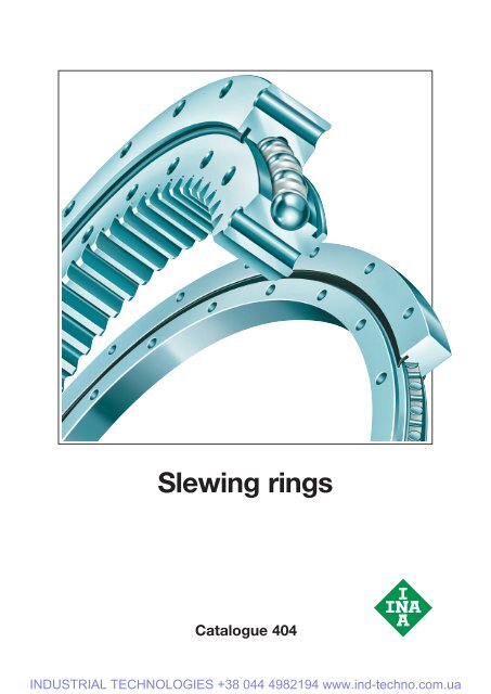
<strong>Slewing</strong> <strong>rings</strong><br />
Catalogue 404<br />
INDUSTRIAL TECHNOLOGIES +38 044 4982194 www.ind-techno.com.ua
404<br />
<strong>Slewing</strong> <strong>rings</strong><br />
For many years, INA has made a decisive contribution to the<br />
development and current level of rolling bearing technology, particularly<br />
through its compact needle roller bea<strong>rings</strong>, high load capacity<br />
cylindrical roller bea<strong>rings</strong> and its diverse range of track rollers for rotary<br />
and linear motion.<br />
INA slewing <strong>rings</strong> are also known worldwide as premium products in<br />
the field of rolling bearing technology. These machine elements have<br />
proved themselves many times over; they have high load carrying<br />
capacity, a versatile range of applications and are highly cost-effective.<br />
Due to their design, a single bearing can reliably support radial,<br />
axial and tilting moment loads. It is therefore possible in many cases<br />
to replace bearing arrangements comprising a combination of radial<br />
and axial bea<strong>rings</strong> by a single bearing. This reduces, in some cases<br />
considerably, the costs and work required in the design of the adjacent<br />
construction and the fitting of bea<strong>rings</strong>.<br />
<strong>Slewing</strong> <strong>rings</strong> are sealed on both sides, lubricated with a high quality<br />
grease, can be relubricated via lubrication nipples and are particularly<br />
easy to fit. The bearing <strong>rings</strong> are supplied without gear teeth or,<br />
in order to achieve simple drive solutions, are available with external<br />
or internal gear teeth.<br />
INA slewing <strong>rings</strong> are designed as:<br />
■ four point contact bea<strong>rings</strong><br />
– these slewing <strong>rings</strong> without preload are robust and proven<br />
under very demanding operation; they place only slight demands<br />
on the flatness and perpendicularity of the adjacent construction<br />
– they are suitable for applications with low requirements for<br />
accuracy and rigidity of the bearing arrangement, for example in<br />
simple metalworking machines, wind power equipment and<br />
construction machinery<br />
■ crossed roller bea<strong>rings</strong><br />
– these preloaded slewing <strong>rings</strong> can support higher loads than<br />
four point contact bea<strong>rings</strong>. They have proved themselves<br />
particularly where bea<strong>rings</strong> are subjected to high radial forces<br />
and moderate axial and tilting moment loads<br />
– they are suitable for applications with uniform running free from<br />
stick-slip, low rotational resistance and high requirements for axial<br />
and radial runout accuracy and rigidity, for example in robots,<br />
handling systems and machine tools.<br />
Catalogue 404 presented here gives comprehensive information<br />
on the reorganised standard range of these slewing <strong>rings</strong>.<br />
The catalogue has been completely revised and replaces<br />
Catalogue 403. Any information in editions that does not concur<br />
with the information is this edition is therefore invalid.<br />
<strong>Schaeffler</strong> <strong>KG</strong><br />
Herzogenaurach (Germany)<br />
INDUSTRIAL TECHNOLOGIES +38 044 4982194 www.ind-techno.com.ua
Product range<br />
Overview/selection scheme<br />
<strong>Slewing</strong> <strong>rings</strong><br />
Characteristics<br />
Rolling element<br />
pitch circle<br />
diameter<br />
VLA 20 VLI 20 VLU 20 from 414 mm<br />
to 1094 mm<br />
Load carrying capacity 4)<br />
radial<br />
stat.<br />
D M kN kN<br />
from 110<br />
to 290<br />
axial on both sides<br />
stat.<br />
from 295<br />
to 770<br />
132 531 132 532 132 533<br />
VSA 20 VSI 20 VSU 20 from 414 mm<br />
to 1094 mm<br />
from 248<br />
to 660<br />
132 552<br />
from 560<br />
to 1490<br />
132 553<br />
Four point contact bea<strong>rings</strong><br />
132 534 132 535 132 536<br />
VSA 25 VSI 25 VSU 25 from 755 mm<br />
to 1055 mm<br />
from 1010<br />
to 1410<br />
132 554<br />
from 2 250<br />
to 3150<br />
132 555<br />
132 537 132 538 132 539<br />
VA 2) VI 2) VU 2) VA =<br />
VI =<br />
VU =<br />
188 mm<br />
to<br />
309 mm<br />
288 mm<br />
to<br />
420 mm<br />
179 mm<br />
to<br />
680 mm<br />
132 556<br />
See dimension table<br />
132 557<br />
132 540 132 541 132 542<br />
XSA 14 XSI 14 XSU 14 from 414 mm<br />
to 1094 mm<br />
from 250<br />
to 670<br />
from 520<br />
to 1360<br />
Crossed roller bea<strong>rings</strong><br />
132 543 132 544 132 545<br />
XA 2) XI 2) XU 2) XA =<br />
XI =<br />
XU =<br />
235 mm<br />
and<br />
352 mm<br />
288 mm<br />
77 mm<br />
to<br />
515 mm<br />
132 558<br />
See dimension table<br />
132 559<br />
132 546 132 547 132 548<br />
1) Special design with INA special plating <strong>Co</strong>rrotect ® .<br />
2) For further designs see dimension table.<br />
3) Values for slewing <strong>rings</strong> with standard clearance.<br />
4) The values relate to the smallest and largest rolling element pitch circle diameter D M per series.<br />
2<br />
INDUSTRIAL TECHNOLOGIES +38 044 4982194 www.ind-techno.com.ua
Requirements for<br />
adjacent<br />
construction<br />
Maximum circumferential Internal clearance Sealed on Operating Anticorrosion<br />
Features<br />
speed with grease<br />
both sides temperature<br />
lubrication 3) matched selectable preloaded<br />
protection 1) See page<br />
low 2 m/s (n · D M = 38 200)<br />
for brief periods<br />
up to 2,6 m/s<br />
(n · D M = 49 700)<br />
❏ ❏<br />
–25 ºC to<br />
+80 ºC ❏<br />
48<br />
low 2 m/s (n · D M = 38 200)<br />
for brief periods<br />
up to 2,6 m/s<br />
(n · D M = 49 700)<br />
❏ ❏<br />
–25 ºC to<br />
+80 ºC ❏<br />
48<br />
low 4 m/s (n · D M = 76 400)<br />
for brief periods<br />
up to 5,2 m/s<br />
(n · D M = 99 500)<br />
❏ ❏<br />
–25 ºC to<br />
+80 ºC ❏<br />
48<br />
low 4 m/s (n · D M = 76 400)<br />
for brief periods<br />
up to 5,2 m/s<br />
(n · D M = 99 500)<br />
❏ ❏<br />
–25 ºC to<br />
+25 ºC ❏<br />
48<br />
moderate 2 m/s (n · D M = 38 200)<br />
for brief periods<br />
up to 2,6 m/s<br />
(n · D M = 49 700)<br />
❏ ❏<br />
–25 ºC to<br />
+80 ºC ❏<br />
78<br />
moderate 2 m/s (n · D M = 38 200)<br />
for brief periods<br />
up to 2,6 m/s<br />
(n · D M = 49 700)<br />
❏ ❏<br />
–25 ºC to<br />
+80 ºC ❏<br />
78<br />
3<br />
INDUSTRIAL TECHNOLOGIES +38 044 4982194 www.ind-techno.com.ua
<strong>Co</strong>ntents<br />
Page<br />
Product range<br />
2 Overview/selection scheme<br />
6 Product index<br />
7 Index of suffixes<br />
8 Ordering designation<br />
9 Ordering example, ordering designation<br />
10 Symbols and units<br />
Technical principles<br />
12 Load carrying capacity and life<br />
12 Static load carrying capacity<br />
12 Definition of static load carrying capacity<br />
12 Checking the static load carrying capacity<br />
15 Calculation example<br />
16 Dynamic load carrying capacity<br />
16 Definition of dynamic load carrying capacity<br />
16 Definition of basic rating life<br />
16 Determining the basic rating life<br />
18 Influences on the operating life of slewing <strong>rings</strong><br />
19 Calculation example<br />
20 Fixing screws<br />
20 Static and dynamic load carrying capacity<br />
20 <strong>Co</strong>nditions for checking load carrying capacity<br />
20 Static limiting load diagrams<br />
21 Static load carrying capacity of fixing screws<br />
21 Dynamic load carrying capacity of fixing screws<br />
22 Rotational resistance<br />
24 Gear teeth<br />
26 Lubrication<br />
27 Grease lubrication<br />
27 Criteria for grease selection<br />
30 Initial greasing<br />
30 Lubrication intervals<br />
31 Grease operating life<br />
31 Relubrication procedure<br />
33 Oil lubrication<br />
34 Sealing of the bearing arrangement<br />
34 INA seal profiles<br />
4<br />
INDUSTRIAL TECHNOLOGIES +38 044 4982194 www.ind-techno.com.ua
Page<br />
36 Design of bearing arrangements<br />
36 Sealing of the bearing position<br />
36 Fixing screws<br />
37 Location by cylindrical pot<br />
37 Dimensioning of the flange thickness<br />
38 Permissible flatness and perpendicularity deviation of the adjacent construction<br />
39 Fitting<br />
40 Delivered condition of slewing <strong>rings</strong><br />
41 Hardness gap on slewing <strong>rings</strong><br />
42 Provision of fasteners<br />
42 Securing of screws<br />
42 General safety and operating guidelines<br />
43 Fitting of slewing <strong>rings</strong><br />
43 Location of slewing <strong>rings</strong><br />
44 Checking and adjustment of tooth flank backlash<br />
44 Measuring the tilting clearance<br />
45 Checking the function<br />
46 Tightening torques and fitting preload forces for fixing screws<br />
Product range<br />
48 Four point contact bea<strong>rings</strong><br />
48 Features<br />
50 Accuracy<br />
52 Dimension tables<br />
78 Crossed roller bea<strong>rings</strong><br />
78 Features<br />
80 Accuracy<br />
82 Dimension tables<br />
Appendix<br />
94 Application examples<br />
Other products<br />
98 Crossed roller bea<strong>rings</strong> for high precision applications<br />
5<br />
INDUSTRIAL TECHNOLOGIES +38 044 4982194 www.ind-techno.com.ua
Product index<br />
sorted alphanumerically<br />
Features<br />
Page<br />
Tables<br />
from page Type Description<br />
– 70 VA Four point contact bearing, external teeth, sealed, selectable<br />
internal clearance, lubrication nipple on circumference of<br />
untoothed ring<br />
– 72 VI Four point contact bearing, internal teeth, sealed, selectable<br />
internal clearance, lubrication nipple on circumference of<br />
untoothed ring<br />
– 74 VU Four point contact bearing, without teeth, sealed, selectable<br />
internal clearance, lubrication nipple on outer ring circumference<br />
48 52 VLA 20 Four point contact bearing, light series 20, external gear teeth,<br />
selectable internal clearance, sealed, lubrication nipple on<br />
circumference of ring without teeth<br />
49 54 VLI 20 Four point contact bearing, light series 20, internal gear teeth,<br />
selectable internal clearance, sealed, lubrication nipple on<br />
circumference of ring without teeth<br />
49 56 VLU 20 Four point contact bearing, light series 20, without gear teeth,<br />
selectable internal clearance, sealed, lubrication nipple on<br />
circumference of outer ring<br />
48 58 VSA 20 Four point contact bearing, standard series 20, external gear<br />
teeth, selectable internal clearance, sealed, lubrication nipple on<br />
circumference of ring without teeth<br />
49 60 VSI 20 Four point contact bearing, standard series 20, internal gear<br />
teeth, selectable internal clearance, sealed, lubrication nipple on<br />
circumference of ring without teeth<br />
49 62 VSU 20 Four point contact bearing, standard series 20, without gear<br />
teeth, selectable internal clearance, sealed, lubrication nipple on<br />
circumference of outer ring<br />
48 64 VSA 25 As VSA 20 but with rolling element diameter 25 mm,<br />
internal clearance matched to series<br />
49 66 VSI 25 As VSI 20 but with rolling element diameter 25 mm,<br />
internal clearance matched to series<br />
49 68 VSU 25 As VSU 20 but with rolling element diameter 25 mm,<br />
internal clearance matched to series<br />
78 88 XA Crossed roller bearing, external gear teeth, preloaded, sealed,<br />
lubrication nipple on circumference of ring without teeth<br />
79 88 XI Crossed roller bearing, internal gear teeth, preloaded, sealed,<br />
lubrication nipple on circumference of ring without teeth<br />
79 90 XU Crossed roller bearing, without gear teeth, preloaded, sealed,<br />
lubrication nipple on circumference of ring without teeth<br />
78 82 XSA 14 Crossed roller bearing, standard series 14, external teeth, sealed,<br />
preloaded, lubrication nipple on circumference of untoothed ring<br />
79 84 XSI 14 Crossed roller bearing, standard series 14, internal teeth, sealed,<br />
preloaded, lubrication nipple on circumference of untoothed ring<br />
79 86 XSU 14 Crossed roller bearing, standard series 14, without teeth, sealed,<br />
preloaded, lubrication nipple on circumference of outer ring<br />
6<br />
INDUSTRIAL TECHNOLOGIES +38 044 4982194 www.ind-techno.com.ua
Index of suffixes<br />
Sorting criteria:<br />
A-Z; special symbols; 1,2,3,...<br />
Suffix<br />
Description<br />
H Hardened gear teeth on bearing ring<br />
N Normalised gear teeth on bearing ring<br />
V Quenched and tempered gear teeth on bearing ring<br />
VSP Bearing with preload<br />
ZT Centring on inner and outer <strong>rings</strong><br />
RR <strong>Co</strong>rrosion-resistant design with INA special plating <strong>Co</strong>rrotect ®<br />
RL0, 1, 2, 3 Restricted internal clearance<br />
7<br />
INDUSTRIAL TECHNOLOGIES +38 044 4982194 www.ind-techno.com.ua
Ordering designation<br />
The ordering designation gives a short description of the<br />
bearing.<br />
It consists of:<br />
■ the designation<br />
■ suffixes<br />
– for special bearing features only.<br />
Designation (Figure 1)<br />
The designation is given in the dimension tables and describes<br />
the standard design of the bearing.<br />
The designation consists of several parts.<br />
It indicates:<br />
■ the type<br />
– four point contact bearing (V), crossed roller bearing (X)<br />
■ the series<br />
– e.g. light series (L)<br />
■ the type of gear teeth<br />
– external teeth (A), internal teeth (I), without teeth (U)<br />
■ the dimension-specific part<br />
– rolling element diameter (D W )<br />
– rolling element pitch circle diameter (D M ).<br />
Suffix (Figure 2)<br />
Suffixes are placed after the dimension-specific part.<br />
They indicate:<br />
■ the heat treatment applied to the gear teeth<br />
– normalised (N), quenched and tempered (V), hardened (H)<br />
■ the special design<br />
– centring on the inner and outer ring (ZT)<br />
– restricted internal clearance for VL 20 (RL0, 1, 2, 3)<br />
– restricted internal clearance for VS 20 (RL0, 1, 2)<br />
– preload for VL 20 and VS 20 (VSP).<br />
VLA 20 1094<br />
Figure 1 · Designation – example of four point contact bearing<br />
VLA 20 1094 N ZT RL2<br />
132 510<br />
Note<br />
For slewing <strong>rings</strong> in accordance with a drawing number<br />
(F- no.), the features Centring, Rotational resistance<br />
and Internal clearance cannot be ordered using suffixes.<br />
For these bea<strong>rings</strong>, the F- number must also be indicated<br />
when ordering.<br />
Figure 2 · Suffix – example of four point contact bearing<br />
132 511<br />
8<br />
INDUSTRIAL TECHNOLOGIES +38 044 4982194 www.ind-techno.com.ua
Ordering example, ordering designation<br />
Four point contact bearing V<br />
Light series<br />
L<br />
External gear teeth<br />
A<br />
Rolling element diameter<br />
20 mm<br />
Rolling element pitch circle diameter 1 094 mm<br />
Normalised gear teeth<br />
N<br />
With centring<br />
ZT<br />
Restricted internal clearance RL2<br />
VLA 20 1094 N ZT RL2<br />
Ordering designation:<br />
VLA 20 1094 N ZT RL2 (Figure 3).<br />
The correct sequence of characters must be observed<br />
when ordering!<br />
1094<br />
20<br />
Figure 3 · Ordering example, ordering designation –<br />
four point contact bearing VLA 20<br />
132 512<br />
9<br />
INDUSTRIAL TECHNOLOGIES +38 044 4982194 www.ind-techno.com.ua
Symbols and units<br />
Unless stated otherwise, the values used<br />
in the text have the following symbols,<br />
units of measurement and definition.<br />
b mm Tooth width<br />
C a kN Basic axial dynamic load dating<br />
C r kN Basic radial dynamic load rating<br />
C 0a kN Basic axial static load rating<br />
C 0r kN Basic radial static load rating<br />
d M mm Mean bearing diameter<br />
D M mm Rolling element pitch circle diameter<br />
D W mm Rolling element diameter<br />
f A – Application factor<br />
f B – Type factor<br />
f L – Raceway factor<br />
f S – Factor for additional safety<br />
F a kN Dynamic axial bearing load<br />
F r kN Dynamic radial bearing load<br />
F zmax kN Maximum permissible tooth force (fracture strength)<br />
F znorm kN Permissible tooth force (fatigue strength)<br />
f 0r – Static radial load factor<br />
F 0a kN Static axial bearing load<br />
F 0q kN Equivalent static axial bearing load<br />
F 0r kN Static radial bearing load<br />
k – Load distribution factor<br />
k F – Dynamic load factor<br />
L 10 6 rev. Basic rating life in millions of revolutions<br />
L h h Basic rating life in operating hours<br />
m mm Tooth modulus<br />
m grease g Grease quantity<br />
M K kNm Dynamic tilting moment load<br />
M W kNm Rotational resistance torque<br />
M 0k kNm Static tilting moment load<br />
M 0q kNm Equivalent static tilting moment load<br />
10<br />
INDUSTRIAL TECHNOLOGIES +38 044 4982194 www.ind-techno.com.ua
n min –1 Operating speed of slewing ring<br />
n osc min –1 Frequency of to and fro movement<br />
p – Life exponent<br />
P kN Equivalent dynamic bearing load<br />
P axial kN Equivalent dynamic axial bearing load<br />
P radial kN Equivalent dynamic radial bearing load<br />
Q spec kN/mm Specific load<br />
W R kN/m Special frictional force due to seals, cages, etc.<br />
x – Profile displacement factor<br />
z – Number of teeth<br />
A – Screw tightening factor<br />
0 ° Transverse pressure angle of gear teeth<br />
° Half of swivel angle<br />
B mm Maximum permissible flatness deviation<br />
W mm Maximum permissible perpendicularity deviation<br />
Stilt mm Maximum permissible increase in tilting clearance<br />
– Load eccentricity parameter<br />
– Frictional resistance factor<br />
11<br />
INDUSTRIAL TECHNOLOGIES +38 044 4982194 www.ind-techno.com.ua
Load carrying capacity and life<br />
Static load carrying capacity<br />
The size of the slewing ring required is dependent on the<br />
demands made on its:<br />
■ static and dynamic load carrying capacity<br />
(Dynamic load carrying capacity see page 16)<br />
■ life (see Dynamic load carrying capacity and life, page16)<br />
■ operational reliability.<br />
Definition of static load carrying capacity<br />
<strong>Slewing</strong> <strong>rings</strong> that undergo rotary motion only infrequently,<br />
undergo slow swivel motion, rotate only slowly or are subjected<br />
to load while stationary are dimensioned on the basis of their<br />
static load carrying capacity since the permissible load in these<br />
cases is determined not by material fatigue but by the loadinduced<br />
deformations at the contact points between the rolling<br />
elements and raceways.<br />
The static load carrying capacity is described by:<br />
■ the basic static load ratings C 0 (see dimension tables)<br />
■ the static limiting load diagrams Raceway and Fixing screws<br />
(see dimension tables and calculation example, page 15).<br />
The size of a statically loaded slewing ring for a particular<br />
application can therefore be checked in approximate terms<br />
using the basic static load ratings C 0 and the static limiting load<br />
diagrams Raceway.<br />
Checking the static load carrying capacity<br />
The static load carrying capacity can be checked in<br />
approximate terms only when:<br />
■ the load arrangement is in accordance with Figure 3<br />
(page 15)<br />
■ all the requirements stated in this publication are fulfilled in<br />
relation to<br />
– flange <strong>rings</strong> and location<br />
– fitting, lubrication and sealing.<br />
Where load arrangements are more complex or the<br />
conditions are not fulfilled, please consult INA.<br />
In order to check the static load carrying capacity, the following<br />
equivalent static operating values must be determined:<br />
■ the equivalent static bearing load F 0q<br />
■ the equivalent static tilting moment load M 0q .<br />
Checking is possible for applications with or without radial load.<br />
Determining the equivalent static bearing load without radial<br />
load and checking the static load carrying capacity in the<br />
static limiting load diagram Raceway<br />
If only axial and tilting moment loads are present, the following<br />
apply:<br />
F 0q<br />
F 0a<br />
⋅ f A<br />
⋅ f S<br />
M 0q<br />
M 0k<br />
⋅ f A<br />
⋅ f S<br />
F 0q kN<br />
Equivalent static axial bearing load<br />
F 0a kN<br />
Static axial bearing load<br />
f A –<br />
Application factor (see Table 1, page 14)<br />
f S –<br />
Factor for additional safety<br />
M 0q kNm<br />
Equivalent static tilting moment load<br />
M 0k kNm<br />
Static tilting moment load.<br />
■ Using the values for F 0q and M 0q , determine the load point<br />
in the static limiting load diagram Raceway.<br />
The load point must be below the raceway curve.<br />
In addition to the raceway, check the dimensioning of the<br />
fixing screws as well (see Calculation example, page 15<br />
and Fixing screws, page 20).<br />
12<br />
INDUSTRIAL TECHNOLOGIES +38 044 4982194 www.ind-techno.com.ua
Determining the equivalent static bearing load with radial<br />
load and checking the static load carrying capacity in the<br />
static limiting load diagram Raceway<br />
Radial loads can only be taken into consideration if the<br />
radial load F 0r is smaller than the basic static radial load<br />
rating C 0 according to the dimension table.<br />
■ Calculate the load eccentricity parameter using the<br />
formula.<br />
■ Determine the static radial load factor f 0r .<br />
This should be done as follows:<br />
– determine the ratio F 0r /F 0a in Figure 1 or Figure 2<br />
– from the ratio F 0r /F 0a and , determine the static radial<br />
load factor f 0r from Figure 1 or Figure 2.<br />
■ Determine the application factor f A according to Table 1,<br />
page 14 and the safety factor f S if required.<br />
■ Calculate the equivalent axial bearing load F 0q and the<br />
equivalent tilting moment load M 0q using the formulae.<br />
■ Using the values for F 0q and M 0q , determine the load<br />
point in the static limiting load diagram Raceway<br />
(see calculation example, page 15).<br />
The load point must be below the raceway curve.<br />
2000⋅<br />
M<br />
= ---------------------------- 0k<br />
⋅<br />
F 0a<br />
D M<br />
F 0q<br />
= F 0a<br />
⋅ f A<br />
⋅ f S<br />
⋅ f 0r<br />
M 0q<br />
= M 0k<br />
⋅ f A<br />
⋅ f S<br />
⋅ f 0r<br />
–<br />
Load eccentricity parameter<br />
M 0k kNm<br />
Static tilting moment load<br />
F 0a kN<br />
Static axial bearing load<br />
D M mm<br />
Rolling element pitch circle diameter (dimension tables)<br />
F 0q kN<br />
Equivalent static axial bearing load<br />
f A –<br />
Application factor (see Table 1, page 14)<br />
f S –<br />
Factor for additional safety<br />
f 0r –<br />
Static radial load factor (see Figure 1 or Figure 2)<br />
M 0q kNm<br />
Equivalent static tilting moment load.<br />
f 0r<br />
11<br />
10<br />
9<br />
8<br />
7<br />
6<br />
5<br />
4<br />
2<br />
Static radial load factor<br />
19<br />
18<br />
17<br />
16<br />
15<br />
14<br />
13<br />
12<br />
3<br />
1<br />
0,5<br />
1<br />
0,25<br />
0 0,2<br />
2<br />
4<br />
3<br />
2<br />
6<br />
8<br />
F /F 0a 0r<br />
0,4 0,6 0,8 1 1,2 1,4 1,6 1,8 2<br />
Load eccentricity factor<br />
Figure 1 · Static radial load factor f 0r for four point contact<br />
bea<strong>rings</strong> and crossed roller bea<strong>rings</strong><br />
f 0r<br />
Static radial load factor<br />
5<br />
4,5<br />
4<br />
3,5<br />
3<br />
2,5<br />
2<br />
1,5<br />
1<br />
2<br />
2<br />
4<br />
3<br />
2<br />
1<br />
0,5<br />
0,25<br />
8<br />
6<br />
F /F 0a 0r<br />
4 6 8 10 12 14 16<br />
Load eccentricity factor<br />
Figure 2 · Static radial load factor f 0r for four point contact<br />
bea<strong>rings</strong> and crossed roller bea<strong>rings</strong><br />
<br />
<br />
132 508<br />
132 509<br />
13<br />
INDUSTRIAL TECHNOLOGIES +38 044 4982194 www.ind-techno.com.ua
Load carrying capacity and life<br />
Application factors<br />
The application factors f A in Table 1 are empirical values.<br />
They take account of the most important requirements – e.g.<br />
the type and severity of operation, rigidity or running accuracy.<br />
If the precise requirements of an application are known,<br />
the values may be altered accordingly.<br />
Application factors 1 must not be used.<br />
A large proportion of applications can be statically<br />
calculated using an application factor of 1 – e.g. bea<strong>rings</strong><br />
for gearboxes and rotary tables.<br />
Safety factors<br />
The factor for additional safety is f S = 1.<br />
It is not normally necessary to factor in any additional safety in<br />
calculation.<br />
In special cases, for example approval specifications,<br />
internal specifications, requirements stipulated by<br />
inspection bodies etc., the appropriate safety factor<br />
should be used.<br />
Table 1 · Application factors for determining the equivalent<br />
static bearing load<br />
Application<br />
Operating/requirement<br />
criteria<br />
f A<br />
Foundry operation Severe conditions 1,5<br />
<strong>Co</strong>nstruction machinery<br />
(e.g. crane, dragline<br />
excavator, vibratory roller)<br />
Severe conditions 1,25<br />
Vehicles and vehicle<br />
attachments<br />
(e.g. lorry-mounted crane)<br />
Severe conditions 1,25<br />
Fork lift trucks and fork Light shocks 1,1<br />
lift truck attachments<br />
Sewage treatment plant Vibrations 1,25<br />
Wind power equipment Risk of false brinelling 2<br />
Robots Rigidity 1,25<br />
Antennae Accuracy 1,5<br />
Machine tools Accuracy 1,5<br />
Measuring equipment Running noise 2<br />
Medical equipment Running noise 1,5<br />
Application<br />
factor<br />
14<br />
INDUSTRIAL TECHNOLOGIES +38 044 4982194 www.ind-techno.com.ua
Calculation example<br />
The four point contact bearing VSI 20 0744 N with internal<br />
gear teeth (see dimension table, page 60) for application<br />
in a crane is to be checked in relation to its static load carrying<br />
capacity.<br />
Given<br />
Static axial bearing load F 0a = 30 kN<br />
Static radial bearing load F 0r = 15 kN<br />
Static tilting moment load M 0k = 70 kNm<br />
Rolling element pitch circle diameter D M = 744 mm<br />
Application factor f A = 1,25 (Table 1)<br />
Safety factor f S = 1<br />
Required<br />
Static load carrying capacity of the bearing.<br />
Solution<br />
2000⋅<br />
M<br />
= ---------------------------- 0k<br />
⋅<br />
2<br />
= ------------------------<br />
000 ⋅ 70<br />
= 6,27<br />
30 ⋅ 744<br />
F<br />
-------- 0r<br />
F 0a<br />
15<br />
= -----<br />
= 0,5 (Figure 2)<br />
30<br />
f 0r = 1,1 (Figure 2)<br />
F 0q<br />
M 0q<br />
F 0a<br />
D M<br />
F 0q<br />
= F 0a<br />
⋅ f A<br />
⋅ f S<br />
⋅ f 0r<br />
= 30 1,25 1 1,1 = 41,25 kN<br />
M 0q<br />
= M 0k<br />
⋅ f A<br />
⋅ f S<br />
⋅ f 0r<br />
= 70 1,25 1 1,1 = 96,25 kNm<br />
Determining the load point in the static limiting load diagram<br />
– checking the static load carrying capacity<br />
Using the values for F 0q and M 0q , the load point in the static<br />
limiting load diagrams Raceway and Fixing screws is<br />
determined (see Figure 3 and Figure 4).<br />
The load point is below the raceway and screw curves.<br />
The four point contact bearing VSI 20 0744 N is adequately<br />
dimensioned and therefore suitable for the application.<br />
Equivalent static tilting moment load<br />
400<br />
kNm<br />
350<br />
300<br />
M0q<br />
250<br />
200<br />
150<br />
100<br />
96,25<br />
50<br />
VSI 20 0744 N<br />
M 0k<br />
F 0a<br />
F 0r<br />
0<br />
0 41,25 400 600 800 1000 1200 1400 1600<br />
kN<br />
Equivalent static axial bearing load F0q<br />
Figure 3 · Static limiting load diagram Raceway –<br />
supported load<br />
220<br />
kNm<br />
200<br />
180<br />
M 160<br />
0q<br />
Equivalent static tilting moment load<br />
140<br />
120<br />
100<br />
96,25<br />
80<br />
60<br />
40<br />
20<br />
VSI 20 0744 N<br />
M 0k<br />
F 0a<br />
F 0r<br />
0<br />
0 41,25 200 400 600 800<br />
Equivalent static axial bearing load F0q<br />
Figure 4 · Static limiting load diagram Fixing screws –<br />
supported load<br />
132 335<br />
kN 1000<br />
132 356<br />
15<br />
INDUSTRIAL TECHNOLOGIES +38 044 4982194 www.ind-techno.com.ua
Load carrying capacity and life<br />
Dynamic load carrying capacity<br />
Dynamically loaded slewing <strong>rings</strong> – i.e. bea<strong>rings</strong> undergoing<br />
predominantly rotary motion – are dimensioned in accordance<br />
with their dynamic load carrying capacity.<br />
Definition of dynamic load carrying capacity<br />
The dynamic load carrying capacity is determined by the fatigue<br />
behaviour of the material. The life as a fatigue period depends<br />
on the load and operating speed of the bearing and the<br />
statistical probability of the first occurrence of failure.<br />
The dynamic load carrying capacity is described by:<br />
■ the basic dynamic load ratings C (see dimension tables)<br />
■ the basic (calculated) rating life L or L h .<br />
The size of a dynamically loaded slewing ring for a particular<br />
application can therefore be checked in approximate terms<br />
using the basic dynamic load ratings and the basis rating life.<br />
Definition of basic rating life<br />
The basis for calculation is the theory of probability, according<br />
to which a defined percentage of a sufficiently large group<br />
of apparently identical bea<strong>rings</strong> achieves or exceeds a<br />
particular number of revolutions before the first evidence of<br />
material fatigue appears. Calculation is based on a requisite<br />
reliability of 90%.<br />
The basic rating life is only an approximate value for<br />
guidance and comparative purposes.<br />
Calculation of an adjusted rating life in accordance<br />
with ISO 281 is recommended if the nominal viscosity of<br />
the lubricant is not achieved for the specific operating<br />
load case (Nominal viscosity see page 33).<br />
Determining the basic rating life<br />
The life formulae for L and L h are only valid:<br />
■ with a load arrangement in accordance with Figure 5<br />
■ if all the requirements stated in this catalogue are fulfilled in<br />
relation to<br />
– flange <strong>rings</strong> and location<br />
– fitting, lubrication and sealing<br />
■ if the load and speed can be regarded as constant during<br />
operation<br />
– if the load and speed are not constant, equivalent<br />
operating values can be determined that will cause<br />
the same fatigue conditions as the actual loads<br />
(see Equivalent operating values, INA Catalogue 307).<br />
■ if the load ratio is F r /F a 8.<br />
If more complex load arrangements are present, a ratio<br />
F r /F a 8 or if the conditions differ from those stated,<br />
please consult INA.<br />
Determining the basic rating life for bea<strong>rings</strong> subjected to<br />
combined loads<br />
For bea<strong>rings</strong> subjected to combined loads – bea<strong>rings</strong><br />
with axial, radial and tilting moment loads – the life L and L h<br />
is calculated as follows:<br />
■ calculate the load eccentricity parameter using the formula<br />
■ determine the ratio of the dynamic radial bearing load F r to<br />
the dynamic axial bearing load F a (F r /F a )<br />
■ using the values for and the ratio F r /F a in Figure 5 or<br />
Figure 6, determine the dynamic load factor k F<br />
■ calculate the equivalent dynamic axial bearing load P axial<br />
using the formula<br />
■ enter the equivalent dynamic axial bearing load P axial and<br />
the basic dynamic axial load rating C a in the life formulae<br />
for L or L h and calculate the life. If swivel operation is<br />
present, enter the operating speed n calculated using the<br />
formula in the life formula L h .<br />
Determining the basic rating life for bea<strong>rings</strong> subjected to<br />
radial loads only<br />
For slewing <strong>rings</strong> subjected to radial loads only, the following<br />
values are entered in the life formulae for L and L h :<br />
■ instead of the equivalent dynamic axial bearing load P axial ,<br />
the equivalent dynamic radial bearing load P radial (i.e. F r )<br />
–P radial =F r<br />
– the basic dynamic radial load rating C r .<br />
16<br />
INDUSTRIAL TECHNOLOGIES +38 044 4982194 www.ind-techno.com.ua
2000⋅<br />
M<br />
= -------------------------- K<br />
⋅<br />
F a<br />
D M<br />
P axial<br />
= k F<br />
⋅ F a<br />
C<br />
L = ⎛---<br />
⎝P⎠<br />
⎞ p<br />
16 666<br />
L h<br />
----------------<br />
C<br />
= ⋅ ⎛---<br />
n ⎝P⎠<br />
<br />
n = n osc<br />
⋅ --------<br />
90°<br />
⎞ p<br />
–<br />
Load eccentricity parameter<br />
M K<br />
kNm<br />
Dynamic tilting moment load<br />
F a<br />
kN<br />
Dynamic axial bearing load<br />
D M<br />
mm<br />
Rolling element pitch circle diameter (dimension table)<br />
P axial , P radial kN<br />
Equivalent dynamic axial or radial bearing load.<br />
This is used for P in the life formulae for L and L h<br />
k F –<br />
Dynamic load factor (see Figure 5 or Figure 6)<br />
L<br />
10 6 rev.<br />
Basic rating life in millions of revolutions<br />
C a , C r kN<br />
Basic dynamic axial or radial load rating according to dimension table.<br />
p –<br />
Life exponent<br />
for four point contact bea<strong>rings</strong>: p = 3<br />
for crossed roller bea<strong>rings</strong>: p = 10/3<br />
L h<br />
h<br />
Basic rating life in operating hours<br />
n min –1<br />
Operating speed of slewing ring<br />
n osc min –1<br />
Frequency of to and fro movement<br />
<br />
<br />
Half of swivel angle<br />
F r<br />
kN<br />
Dynamic radial bearing load.<br />
k F<br />
Dynamic radial load factor<br />
50<br />
40<br />
30<br />
20<br />
10<br />
5<br />
4<br />
3<br />
2<br />
F r/Fa<br />
8<br />
6<br />
4<br />
2<br />
1 0,5<br />
0<br />
1 0 2 4 6 8<br />
M k<br />
F a<br />
Load eccentricity factor<br />
10 12 14 16<br />
Figure 5 · Dynamic load factor k F for four point contact<br />
bea<strong>rings</strong><br />
k F<br />
Dynamic radial load factor<br />
50<br />
40<br />
30<br />
20<br />
10<br />
5<br />
4<br />
3<br />
2<br />
F r/ Fa<br />
8<br />
6<br />
4<br />
2<br />
1<br />
0,5<br />
0<br />
1 0 2 4 6 8<br />
Load eccentricity factor<br />
Figure 6 · Dynamic load factor k F for crossed roller bea<strong>rings</strong><br />
<br />
M k<br />
F a<br />
F r<br />
10 12 14 16<br />
<br />
F r<br />
132 514<br />
132 515<br />
17<br />
INDUSTRIAL TECHNOLOGIES +38 044 4982194 www.ind-techno.com.ua
Load carrying capacity and life<br />
Influences on the operating life of slewing <strong>rings</strong><br />
The operating life is defined as the life actually achieved by a<br />
slewing ring. This can deviate significantly from the calculated<br />
basic rating life due to wear and/or fatigue.<br />
Possible causes include:<br />
■ oscillating bearing motion with very small swivel angles –<br />
false brinelling<br />
■ vibration while the bearing is stationary<br />
■ unsuitable design or deformation of the adjacent<br />
construction<br />
■ excessively high operating temperatures<br />
■ incorrect maintenance or lubrication<br />
■ contamination<br />
■ incorrect fitting<br />
■ preload of the fixing screws.<br />
Due to the variety of installation and operating conditions,<br />
it is not possible to precisely predetermine the operating life.<br />
The most reliable way of arriving at a close estimate is by<br />
comparison with similar applications.<br />
18<br />
INDUSTRIAL TECHNOLOGIES +38 044 4982194 www.ind-techno.com.ua
Calculation example<br />
For the crossed roller bearing XSU 14 0544 without gear teeth<br />
(see dimension table, page 86), the basic rating life L h in<br />
operating hours is to be determined.<br />
50<br />
40<br />
30<br />
L<br />
Given<br />
Dynamic axial bearing load F a = 80 kN<br />
Dynamic radial bearing load F r = 40 kN<br />
Dynamic tilting moment load M K = 32 kNm<br />
Operating speed n = 2 min –1<br />
Life exponent<br />
for crossed roller bea<strong>rings</strong> p = 10/3<br />
Basic dynamic axial load rating of<br />
slewing ring (according to<br />
dimension table, page 86) C a = 270 kN<br />
Rolling element pitch circle diameter D M = 544 mm<br />
Required<br />
Basic rating life L h .<br />
20<br />
k F 10<br />
Dynamic radial load factor<br />
5<br />
4<br />
3,3<br />
3<br />
2<br />
M k<br />
F a<br />
F r<br />
Solution<br />
2000⋅<br />
M<br />
= -------------------------- K<br />
⋅<br />
F a<br />
D M<br />
1 0 2 4 6 8<br />
1,47<br />
Load eccentricity factor <br />
10 12 14 16<br />
Figure 7 · Dynamic load factor k F for crossed roller bea<strong>rings</strong><br />
132 516<br />
2<br />
= ------------------------<br />
000 ⋅ 32<br />
= 1,47<br />
80 ⋅ 544<br />
F r<br />
-----<br />
40<br />
= -----<br />
= 0,5<br />
80<br />
F a<br />
k F = 3,3 (Figure 7)<br />
P axial<br />
= k F<br />
⋅ F a<br />
P axial = 3,3 · 80 kN = 264 kN<br />
C a<br />
16 666<br />
L h<br />
= ---------------- ⋅ ⎛-------------<br />
n ⎝ ⎠<br />
P axial<br />
⎞ p<br />
10<br />
-----<br />
3<br />
16 666 270<br />
L h = ---------------- ⋅ ⎛---------<br />
⎞ = 8980 h<br />
2 ⎝264⎠<br />
19<br />
INDUSTRIAL TECHNOLOGIES +38 044 4982194 www.ind-techno.com.ua
Fixing screws<br />
Static and dynamic load carrying capacity<br />
In addition to the raceway, the load carrying capacity of the<br />
fixing screws must also be checked. This is based on the<br />
information in the section Static load carrying capacity<br />
(page 12).<br />
<strong>Co</strong>nditions for checking load carrying capacity<br />
The load carrying capacity of the fixing screws can be checked<br />
if the following conditions are fulfilled:<br />
■ the criteria in the section Static load carrying capacity are<br />
fulfilled<br />
■ the bearing load is supported; i.e. the bearing is installed<br />
such that the axial load relieves the screws<br />
– if the load is suspended, the screws are subjected to<br />
tensile forces by the axial load and must be of larger<br />
dimensions. In such applications, please consult INA<br />
■ the screws are tightened as specified using a torque wrench<br />
– screw tightening factor A =1,6,<br />
tightening torques according to Table 3, page 46<br />
■ the permissible contact pressure (page 36 and page 42)<br />
is not exceeded.<br />
If the actual conditions vary from those stated or if more<br />
complex load arrangements are present, please consult INA.<br />
Indicator of load carrying capacity<br />
The load carrying capacity of the screws is described by:<br />
■ the curves in the static limiting load diagrams Fixing screws<br />
(Figure 1 and dimension tables)<br />
■ the maximum permissible radial load F rperm (friction locking)<br />
in the dimension tables.<br />
220<br />
kNm<br />
200<br />
180<br />
M 160<br />
0q<br />
Equivalent static tilting moment load<br />
140<br />
120<br />
100<br />
96,25<br />
80<br />
60<br />
40<br />
20<br />
VSI 20 0744 N<br />
0<br />
0 41,25 200 400 600 800<br />
Equivalent static axial bearing load F0q<br />
kN 1000<br />
Figure 1 · Static limiting load diagram Fixing screws – example<br />
for four point contact bearing VSI 20 0744 N<br />
132 517<br />
Static limiting load diagrams<br />
The screw curves are given in the static limiting load diagrams<br />
Fixing screws (see example in Figure 1) – the required safety<br />
factors have been included. The curves are based on screws<br />
of grade 10.9, tightened to 90% of their proof stress including<br />
the torsion content.<br />
If screws of grade 8.8 or 12.9 are used, the equivalent<br />
static loads F 0q and M 0q (see Static load carrying capacity,<br />
page 12 and page 13) must be converted using the following<br />
factors:<br />
■ Grade 8.8<br />
–F 0q 1,65, M 0q 1,65<br />
■ Grade 12.9<br />
–F 0q 0,8, M 0q 0,8.<br />
20<br />
INDUSTRIAL TECHNOLOGIES +38 044 4982194 www.ind-techno.com.ua
Static load carrying capacity of fixing screws<br />
The static load carrying capacity of the screw is limited by its<br />
proof stress.<br />
Checking the static load carrying capacity without radial load<br />
■ From the equivalent static load F 0q and M 0q<br />
(see Static load carrying capacity, page 12 or page 13),<br />
determine the load point in the static limiting load diagram<br />
Fixing screws (see example in Figure 1).<br />
The load point must be below the appropriate screw<br />
curve (see example in Figure 1).<br />
Checking the static load carrying capacity with radial load<br />
The screw connections must prevent displacement of the<br />
bearing <strong>rings</strong> in relation to the adjacent construction.<br />
In addition to the initial checking, the following check<br />
must also be carried out with radial load:<br />
■ the maximum external radial load multiplied by the<br />
application factor f A is compared with the maximum<br />
permissible radial load F rperm in the dimension tables<br />
– the values are valid for screws of grade 10.9.<br />
Factoring in the radial load gives guide values only.<br />
For high radial loads (F r /F a 4), please consult INA.<br />
Dynamic load carrying capacity of fixing screws<br />
The dynamic load carrying capacity is the load that can be<br />
supported “permanently” by the screws. This corresponds to<br />
the fatigue strength of the screw.<br />
Checking the dynamic load carrying capacity<br />
■ From the dynamic loads present, determine the equivalent<br />
loads F 0q and M 0q in accordance with the section<br />
Load carrying capacity and life, page 12 or page 13<br />
– instead of the application factor, the operating load must<br />
be increased by a factor according to Table 1<br />
■ Check the load carrying capacity in the static limiting load<br />
diagram Fixing screws<br />
– the load point must be below the appropriate screw curve<br />
(see example in Figure 1).<br />
Table 1 · Factor for increasing the operating load<br />
Screw grade<br />
Increase factor<br />
8.8 1,8<br />
10.9 1,6<br />
12.9 1,5<br />
21<br />
INDUSTRIAL TECHNOLOGIES +38 044 4982194 www.ind-techno.com.ua
Rotational resistance<br />
The rotational resistance of slewing <strong>rings</strong> is essentially<br />
determined by:<br />
■ the rolling resistance of the rolling elements<br />
■ the internal clearance or bearing preload<br />
■ the friction of the spacers or the cage or cage segments<br />
■ the seals.<br />
The rotational resistance is also influenced by a large number<br />
of other parameters.<br />
These include:<br />
■ the preload and lubrication of the seals<br />
■ the quantity of grease in the bearing<br />
■ the manufacturing tolerances<br />
■ the change in the internal clearance due to fitting<br />
■ the deformation of the adjacent construction.<br />
Calculation of the rotational resistance<br />
The rotational resistance torque M W can only be calculated in<br />
approximate terms using the influences stated.<br />
The factors required for calculation are given in Table 1.<br />
M W<br />
D<br />
------------- M<br />
k ⎛<br />
M K<br />
⋅ 1000<br />
2000<br />
------------------------- + Fr ⋅<br />
------------ f L + F a<br />
----- ⎞ + D M<br />
⋅ W R<br />
= ⋅ ⎛ ⋅ ⋅<br />
-------------------- ⎞<br />
⎝ ⎝<br />
2 k ⎠ 1000 ⎠<br />
D M<br />
M W kNm<br />
Rotational resistance torque<br />
D M mm<br />
Rolling element pitch circle diameter (dimension table)<br />
–<br />
Frictional resistance factor (Table 1)<br />
k –<br />
Load distribution factor (Table 1)<br />
M K kNm<br />
Dynamic tilting moment load<br />
F r kN<br />
Dynamic radial bearing load<br />
f L –<br />
Raceway factor (Table 1)<br />
F a kN<br />
Dynamic axial bearing load<br />
W R kN/m<br />
Specific frictional force due to seals, cages, etc. (Table 1).<br />
Table 1 · Factors for determining the rotational resistance<br />
Bearing type k f L W R<br />
Four point<br />
contact bearing<br />
VL 20, VS 20<br />
Standard<br />
clearance<br />
and preload<br />
Four point contact bearing<br />
VS 25, V<br />
Crossed roller bearing<br />
XS 14, X<br />
0,01 4,37 1,73 1) 0,21<br />
0,005 4,37 1,73 1) 0,21<br />
0,004 4,08 1<br />
( 0,44 ⋅ D<br />
1<br />
M )<br />
– ----------------------------<br />
1000<br />
1) The values are valid for a load consisting predominantly of tilting<br />
moment and axial force;<br />
f L = 1 for predominantly radial load if:<br />
F r (450 · M K /D M )+0,1·F a .<br />
22<br />
INDUSTRIAL TECHNOLOGIES +38 044 4982194 www.ind-techno.com.ua
The values determined using the formula may differ<br />
considerably from the actual values due to the influence<br />
of the aforementioned factors, e.g.:<br />
■ in the case of bea<strong>rings</strong> subjected to low load or zero load<br />
■ due to the flatness and perpendicularity deviation of the<br />
adjacent construction<br />
M K<br />
⋅ 2000<br />
■ for a ratio -------------------------- < 1.<br />
⋅<br />
D M<br />
F a<br />
If the rotational resistance for the specific application is<br />
considerably less than the value calculated using the formula,<br />
please consult INA.<br />
If four point contact bea<strong>rings</strong> of series VL 20 or VS 20 are<br />
used for spool bearing arrangements, large fluctuations<br />
in rotational resistance must be anticipated due to the<br />
nature of the application.<br />
Dimensioning of rotary drives<br />
For the dimensioning of rotary drives, account must be taken<br />
not only of the rotational resistance of the bearing but also:<br />
■ the acceleration power<br />
■ any tilted positioning of the machines<br />
■ any wind forces acting on the bearing arrangement.<br />
If precise values are not available, the value of M W used should<br />
be doubled.<br />
23<br />
INDUSTRIAL TECHNOLOGIES +38 044 4982194 www.ind-techno.com.ua
Gear teeth<br />
INA slewing <strong>rings</strong> are available in the following designs:<br />
■ with external gear teeth (A)<br />
■ with internal gear teeth (I)<br />
■ without gear teeth (U).<br />
The letters A, I, U indicate the type of gear teeth –<br />
for the composition of the designation, see the section<br />
Ordering example and ordering designation, page 8.<br />
Design and quality of gear teeth<br />
As standard, the gear teeth on slewing <strong>rings</strong> are involute gear<br />
teeth without addendum modification ( 0 =20°).<br />
The gear teeth are of quality 12e28 or 12e29 and, in the case<br />
of the standard series XS 14, 10e27, in accordance with<br />
DIN 3 960, DIN 3 962-1 and DIN 3 967. Deviations are<br />
indicated in the dimension tables.<br />
The runout of the gear teeth deviates from DIN 3 962 and is<br />
defined as the variation in wall thickness between the rolling<br />
element pitch circle diameter and the pitch circle diameter of<br />
the gear teeth (see Accuracy, page 50 and page 80).<br />
The bottom clearance is 0,25modulus and the minimum<br />
dedendum is 1,25modulus (reference profile to DIN 867).<br />
In order to prevent meshing interference, the tip on external<br />
gear teeth is reduced. This allows the use of pinions with a small<br />
number of teeth (at least 14 teeth).<br />
Four point contact bea<strong>rings</strong> VA and crossed roller bea<strong>rings</strong> XA<br />
are designed in some cases without a tip reduction<br />
(see dimension tables).<br />
Material and heat treatment<br />
The heat treatment of the gear teeth is characterised by means<br />
of suffixes:<br />
■ normalised (N)<br />
– standard design of gear <strong>rings</strong><br />
■ quenched and tempered (V)<br />
– special design of gear <strong>rings</strong><br />
■ hardened (H)<br />
– special design of gear <strong>rings</strong>.<br />
Example:<br />
VLA 20 0414 N.<br />
Four point contact bearing, light series 20, normalised<br />
gear teeth.<br />
For the composition of the suffix, see the section<br />
Ordering designation, page 8.<br />
Standard design of gear teeth<br />
<strong>Slewing</strong> <strong>rings</strong> with gear <strong>rings</strong> made from normalised material<br />
C45N or 42CrMo4V65 (suffix N) have proved themselves in a<br />
wide range of applications.<br />
The permissible tooth forces for each bearing are indicated in<br />
the dimension tables.<br />
Special designs of gear teeth<br />
If the permissible tooth forces indicated in the dimension tables<br />
are exceeded as a result of high circumferential forces, the<br />
gear teeth may be quenched and tempered. This increases<br />
the permissible tooth force by approximately 20%. The notch<br />
impact toughness in the low temperature range is also<br />
improved.<br />
The gear ring material for the quenched and tempered design<br />
is 42CrMo4V, suffix V.<br />
If there are particularly high requirements for the life of the<br />
gear teeth, the contour of the gear teeth can be hardened.<br />
The flanks and root of the teeth are hardened simultaneously.<br />
These slewing <strong>rings</strong> are indicated by the suffix H.<br />
The special designs “V” and “H” are only available by agreement<br />
for large quantities.<br />
Further information on special designs is given in the<br />
dimension tables.<br />
Tooth forces<br />
The tooth forces F z in the dimension tables have the following<br />
definitions:<br />
F z norm = permissible tooth force<br />
(tooth base fatigue strength at a shock factor of 1,2).<br />
F z max = maximum permissible tooth force<br />
(tooth base fracture strength at a shock factor<br />
of 1,35).<br />
The values are applicable to:<br />
■ hardened and ground drive pinions<br />
■ tooth quality of the drive pinion 7b26<br />
■ driving pinion<br />
– with a driving wheel, the permissible value is 90% of the<br />
F z value<br />
■ suspended pinion bearing arrangement<br />
■ swivelling operation<br />
– the maximum swivel speed is 1,5 m/s.<br />
For other shock factors (see Table 1), the tooth forces indicated<br />
in the dimension tables can be converted on a linear basis.<br />
24<br />
INDUSTRIAL TECHNOLOGIES +38 044 4982194 www.ind-techno.com.ua
A selection of the usual shock factors for gear teeth is given in<br />
Table 1 – for other operating conditions, please consult INA.<br />
The shock factors are guide values for conversion of the tooth<br />
forces F znorm and F zmax .<br />
Table 1 · Shock factors for gear teeth<br />
Driven unit<br />
<strong>Slewing</strong> gear<br />
<strong>Co</strong>nveyor belts<br />
(continuous)<br />
Generators<br />
Sewage treatment plant<br />
Antenna bearing<br />
arrangements<br />
Medical equipment<br />
(X-ray equipment etc.)<br />
Measuring equipment<br />
<strong>Slewing</strong> gear in cranes<br />
Mixers<br />
Rolling mills<br />
Machine tool drives<br />
Vehicles<br />
Gearboxes<br />
Robots<br />
Wind power equipment<br />
Leisure equipment<br />
Lifting gear<br />
Piston pumps<br />
Fork lift trucks<br />
Fork lift truck<br />
attachments<br />
Nail manufacturing<br />
machines<br />
<strong>Co</strong>nstruction machinery<br />
Excavators<br />
Crushers<br />
Drilling equipment<br />
<strong>Co</strong>ld rolling mills<br />
Opencast mining<br />
equipment<br />
Bark removal machines<br />
Operation Drive unit<br />
Uniform<br />
operation<br />
Moderate<br />
shocks<br />
Medium<br />
shocks<br />
Severe<br />
shocks<br />
Electric motor/<br />
hydraulic<br />
motor<br />
Shock factor<br />
Internal<br />
combustion<br />
engine<br />
Shock factor<br />
norm. max. norm. max.<br />
1 1,1 1,1 1,25<br />
1,2 1,35 1,3 1,5<br />
1,35 1,6 1,5 1,75<br />
1,6 1,85 1,7 2<br />
Drive pinion<br />
If no particular transmission ratio is required, the following<br />
pinions in a hardened and ground design are suitable:<br />
■ pinions with 17 teeth without addendum modification<br />
■ pinions with 14 teeth and an addendum modification factor<br />
of x = +0,5.<br />
A tip reduction of 0,1modulus is recommended.<br />
The gear tooth width of the pinion should project beyond the<br />
tooth width of the slewing ring on both sides by at least<br />
0,5modulus.<br />
In order to minimise the wear rate at low circumferential<br />
speeds (v 0,1 m/s), a quenched and tempered pinion of<br />
tooth quality 9b27 should be used. The permissible load<br />
carrying capacity of the gear pair is normally restricted by<br />
the load carrying capacity of the pinion.<br />
The bearing arrangement of the drive pinion must be designed<br />
such that the pinion deflection under load is as small as<br />
possible.<br />
Individual values for the gear pair can be calculated on request.<br />
Tooth flank backlash<br />
On toothed bearing <strong>rings</strong>, there is a green mark on the tooth tip<br />
at the point with the largest ring width (the largest distance<br />
between the rolling element pitch circle diameter D M and the<br />
pitch circle diameter of the gear teeth). During fitting, the<br />
required tooth flank backlash (0,03 to 0,04modulus) must be<br />
set here – see Fitting, page 44.<br />
Binding during operation can be prevented by the correctly<br />
adjusted tooth flank backlash.<br />
The flank backlash can, for example, be eliminated by a drive<br />
pinion preloaded by a spring. It must be ensured, however,<br />
that sufficient bottom clearance is maintained.<br />
Appropriate information is given in the technical literature.<br />
Lubrication of the gear teeth<br />
Suitable lubricants for the gear teeth are indicated in the section<br />
Lubrication, page 32, Table 3.<br />
25<br />
INDUSTRIAL TECHNOLOGIES +38 044 4982194 www.ind-techno.com.ua
Lubrication<br />
<strong>Co</strong>rrect lubrication and regular maintenance are important<br />
preconditions for achieving a long operating life with slewing<br />
<strong>rings</strong>.<br />
The lubricant serves to:<br />
■ form a lubricant film capable of supporting loads on all<br />
contact surfaces<br />
■ seal the bearing against external influences (in the case<br />
of grease lubrication) and thus prevent the ingress of solid<br />
and liquid contaminants<br />
■ reduce the running noise<br />
■ protect the bearing against corrosion<br />
■ dissipate heat from rolling bearing subjected to heavy loads<br />
(in the case of oil lubrication).<br />
Type of lubrication<br />
<strong>Slewing</strong> <strong>rings</strong> can be lubricated with grease or oil.<br />
The decisive factors in determining the appropriate type<br />
of lubrication and quantity of lubricant required are:<br />
■ the design and size of the bearing<br />
■ the design of the bearing environment<br />
■ the lubricant feed<br />
■ the operating conditions.<br />
Lubrication of the gear teeth<br />
The points stated above apply to the gear teeth of slewing<br />
<strong>rings</strong>.<br />
The lubricant used should have good adhesion.<br />
Suitable lubricants are given in Table 3, page 32.<br />
26<br />
INDUSTRIAL TECHNOLOGIES +38 044 4982194 www.ind-techno.com.ua
Lubrication<br />
Grease lubrication<br />
Criteria for grease selection<br />
Operating temperature range (Figure 1)<br />
The range must correspond to the potential range of<br />
temperatures in the rolling bearing.<br />
The possible operating temperatures should not exceed<br />
the upper and lower limit values:<br />
■ the maximum operating temperature should be +20 °C<br />
less than the upper limit value<br />
■ the minimum operating temperature should be +20 °C<br />
above the lower limit value. At very low temperatures,<br />
greases release very little base oil. This can result in<br />
inadequate lubrication.<br />
20˚<br />
Upper limit value<br />
Operating temperature<br />
-25˚<br />
20˚<br />
-25˚<br />
50˚<br />
0˚ 0˚<br />
100˚<br />
50˚<br />
120˚<br />
100˚<br />
120˚<br />
Lower limit value<br />
Type of grease (Figure 2)<br />
The characteristics of a grease depend on:<br />
■ the base oil<br />
■ the viscosity of the base oil<br />
– important for the speed range<br />
■ the thickener<br />
– the shear strength is important for the speed range<br />
■ the additives.<br />
Figure 1 · Operating temperature range<br />
Thickener<br />
Additives<br />
132 569<br />
<strong>Co</strong>nsistency of greases (Figure 3)<br />
Greases are divided into consistency classes – known as NLGI<br />
grades (DIN 51818). Grades 1, 2 and 3 are preferred for<br />
rolling bea<strong>rings</strong>.<br />
The greases should not become:<br />
■ too soft at high temperatures (NLGI 1)<br />
■ too stiff at low temperatures (NLGI 3).<br />
Greases should be selected by their speed parameter<br />
n·d M :<br />
– greases with a low speed parameter should be used<br />
for bea<strong>rings</strong> running at low speeds.<br />
The consistency of polycarbamide greases can be altered<br />
by shear stresses.<br />
Figure 2 · Type of grease<br />
55 60<br />
50<br />
45<br />
40<br />
35<br />
sec<br />
30 25<br />
5<br />
10<br />
15<br />
20<br />
Grease<br />
Base oil<br />
155 179<br />
NLGI 3<br />
NLGI 1<br />
155 180<br />
Figure 3 · <strong>Co</strong>nsistency of greases<br />
27<br />
INDUSTRIAL TECHNOLOGIES +38 044 4982194 www.ind-techno.com.ua
Lubrication<br />
Grease lubrication<br />
Behaviour in the presence of water (Figure 4)<br />
Water in the grease has a highly detrimental effect on the<br />
operating life of the bearing:<br />
■ the behaviour of greases in the presence of water is<br />
assessed according to DIN 51807 (see Table 1)<br />
■ the anti-corrosion characteristics can be checked in<br />
accordance with DIN 51802 – information is given in the<br />
grease manufacturer’s data sheets.<br />
Blank<br />
1<br />
20<br />
3 h<br />
˚C<br />
3 h<br />
˚C<br />
90<br />
Pressure properties<br />
■ The viscosity must be sufficiently high at the operating<br />
temperature for the formation of a lubricant film capable of<br />
supporting loads<br />
■ At high loads, greases with EP (extreme pressure)<br />
characteristics and high base oil viscosity should be used<br />
(KP grease to DIN 51502)<br />
■ Silicone greases should only be used with low loads<br />
(P 3% C).<br />
The load-supporting capability of common greases can<br />
change if EP additives containing lead are not used.<br />
Therefore:<br />
– check the grease selection<br />
– consult the lubricant manufacturer.<br />
Grease<br />
80 40<br />
Sample<br />
10<br />
0 0<br />
Glass slide<br />
Figure 4 · Behaviour in the presence of water to DIN 51807<br />
155 181<br />
Table 1 · Bearing greases for initial greasing<br />
INA<br />
designation<br />
Designation to<br />
DIN 51825<br />
Type of grease<br />
SM03 KP2N–20 Lithium complex soap<br />
grease (mineral oil base)<br />
Temperature<br />
range<br />
NLGI grade<br />
(consistency)<br />
Speed<br />
parameter<br />
n·d M<br />
Kinematic<br />
viscosity at<br />
40 °C (base oil)<br />
°C min –1 mm mm 2 s –1<br />
–25 1) to +150 2 500 000 160 1–90<br />
Behaviour in the<br />
presence of<br />
water to<br />
DIN 51807<br />
1) Determined according to IP 186/85.<br />
28<br />
INDUSTRIAL TECHNOLOGIES +38 044 4982194 www.ind-techno.com.ua
Miscibility<br />
The preconditions for miscibility are as follows:<br />
■ same base oil<br />
■ compatible thickener types<br />
■ similar base oil viscosities<br />
– the difference must not be more than one ISO VG class<br />
■ same consistency – NLGI grade.<br />
If greases are to be mixed with each other, contact the<br />
grease manufacturer.<br />
Storage (Figure 5)<br />
Lubricants age due to environmental influences.<br />
The information provided by the lubricant manufacturer<br />
should be adhered to.<br />
INA uses greases with a mineral oil base. Experience shows<br />
that these greases can be stored for up to 3 years.<br />
The preconditions for storage are:<br />
■ closed room or store<br />
■ temperatures between 0 °C and +40 °C<br />
■ relative atmospheric humidity not more than 65%<br />
■ no contact with chemical agents (vapours, gases or fluids)<br />
■ rolling bea<strong>rings</strong> sealed.<br />
The start-up frictional torque of greased bea<strong>rings</strong> may<br />
temporarily be higher than normal after extended periods of<br />
storage. The lubricity of the grease may also have deteriorated.<br />
Greases – even those obtained from the same<br />
manufacturer – may vary in their characteristics.<br />
Therefore, INA does not accept any liability for lubricants<br />
and their behaviour during operation.<br />
155 186<br />
2004<br />
2005<br />
Figure 5 · Storage<br />
2006<br />
max. 65%<br />
˚C<br />
40<br />
0<br />
90<br />
80<br />
100 0<br />
%<br />
10<br />
20<br />
30<br />
70<br />
40<br />
60 50<br />
29<br />
INDUSTRIAL TECHNOLOGIES +38 044 4982194 www.ind-techno.com.ua
Lubrication<br />
Grease lubrication<br />
Initial greasing<br />
INA crossed roller bea<strong>rings</strong> are supplied greased (for the grease<br />
used, see Table 1, page 28). The grease is a high quality<br />
lithium complex soap grease with a mineral oil base in<br />
accordance with DIN 51825–KP2N–20 and is suitable for<br />
temperatures from –25 °C to +150 °C<br />
The total grease quantity can be calculated in approximate<br />
terms using the following formulae. Calculation gives a grease<br />
quantity that approximately fills the available free space in<br />
the raceway system of the bearing.<br />
Grease quantity for four point contact bea<strong>rings</strong>:<br />
2<br />
D<br />
m M ⋅ D W ⋅0,7<br />
grease<br />
= ------------------------------------<br />
1000<br />
Grease quantity for crossed roller bea<strong>rings</strong>:<br />
D ⋅ 2<br />
m M<br />
D W ⋅0,5<br />
grease<br />
= ------------------------------------<br />
1000<br />
m grease g<br />
Grease quantity<br />
D M mm<br />
Rolling element pitch circle diameter (dimension table)<br />
D W mm<br />
Rolling element diameter.<br />
Lubrication intervals<br />
The lubrication intervals are essentially dependent on:<br />
■ the operating conditions<br />
■ the environmental influences such as contamination,<br />
water, etc.<br />
■ the type of slewing ring.<br />
The lubrication intervals can only be determined by<br />
means of tests under the specific application conditions:<br />
– sufficiently long observation periods must be allowed<br />
– the condition of the grease must be checked at regular<br />
intervals.<br />
If comparable results are not available, guide values for the<br />
lubrication interval are given in Table 2.<br />
The values are based on the following conditions:<br />
■ operating temperature +70 °C<br />
■ circumferential speed 0,5 m/s<br />
■ low to moderate load.<br />
Table 2 · Guide values for the relubrication interval<br />
Operating condition 1) Relubrication interval (guide value) 2)<br />
Dry, clean rooms,<br />
approx. 500 h<br />
e.g. rotary tables, robots<br />
Severe contamination,<br />
approx. 50 to 200 h<br />
operation outdoors<br />
e.g. crane, hydraulic excavator<br />
Extreme contamination,<br />
e.g. drilling equipment in<br />
steelworks plant<br />
<strong>Co</strong>ntinuous relubrication by means<br />
of central lubrication systems or<br />
lubrication cartridges<br />
1) For other operating conditions, please consult INA.<br />
2) For the gear teeth, the guide values should be taken as half the<br />
stated values.<br />
<strong>Slewing</strong> <strong>rings</strong> – the raceway and gear teeth – must always<br />
be relubricated:<br />
– after any cleaning, e.g. after spraying with water,<br />
steam etc.<br />
– before and after extended periods of stoppage,<br />
e.g. for cranes and construction machinery during<br />
the winter months<br />
– in conditions of high humidity.<br />
30<br />
INDUSTRIAL TECHNOLOGIES +38 044 4982194 www.ind-techno.com.ua
Grease operating life<br />
If relubrication is not possible, the grease operating life<br />
becomes the decisive factor.<br />
Based on experience, the guide value for the grease operating<br />
life in the majority of applications is higher than the guide<br />
value for the relubrication interval by a factor of 2.<br />
At operating temperatures above +70 ºC, the lubrication<br />
interval and therefore the grease operating life are<br />
reduced.<br />
In order to ensure operational reliability, the grease<br />
operating life should not exceed 3 years.<br />
Relubrication procedure<br />
Table 3, page 32, shows suitable lubricants for the raceway and<br />
gear teeth.<br />
If slewing <strong>rings</strong> operate under high to very high load and at low<br />
to very low speeds, lubricants with base oils up to ISO VG 1500<br />
can be used in order to improve the lubricant film, depending<br />
on the operating temperature. In such applications, please<br />
consult INA.<br />
The maintenance of bea<strong>rings</strong> is described in detail in<br />
INA Technical Product Information TPI 13. This TPI is available<br />
upon request from INA.<br />
Raceway<br />
During the lubrication procedure, foreign matter such as<br />
contaminants, dust, spray water and condensation that have<br />
entered the slewing ring are pressed out.<br />
If possible, the grease used for relubrication should be the same<br />
as that used in initial operation.<br />
Lubrication should always be carried out on bea<strong>rings</strong> that are<br />
warm from operation:<br />
■ clean the lubrication nipples.<br />
■ grease should then be pressed into the lubrication nipples<br />
until a collar of fresh grease forms around both seals<br />
(one bearing ring should slowly rotated during this process)<br />
– the old grease must be allowed to flow out unhindered.<br />
Before initial operation, it must be ensured that all the<br />
lubricant ducts to the bearing are filled with lubricant.<br />
Gear teeth<br />
If possible, the grease used should be the same as that used in<br />
initial operation.<br />
■ The gear teeth, especially the tooth root surface, must be<br />
cleaned.<br />
■ The gear teeth must be sprayed or brushed with grease.<br />
31<br />
INDUSTRIAL TECHNOLOGIES +38 044 4982194 www.ind-techno.com.ua
Lubrication<br />
Grease lubrication<br />
Lubrication using lubrication cartridges<br />
Lubrication cartridges allow continuous relubrication of slewing<br />
<strong>rings</strong> up to 24 months. They are an independent greasing<br />
system and are thus also suitable for retrofitting.<br />
The cartridges are filled with grease and located directly on the<br />
bearing or on the adjacent construction.<br />
If the lubrication cartridges are applied to the adjacent<br />
construction, the grease is fed to the bearing via lubricant<br />
pipes.<br />
Information on the use and handling of lubrication cartridges<br />
can be obtained from the relevant manufacturers.<br />
Table 3 · Lubricants for the raceway and gear teeth<br />
Raceway Gear teeth Temperature range 1) Manufacturer<br />
Aralub HLP 2 Aralub LFZ 1 –30 °C to +130 °C Aral<br />
Energrease LS–EP 2 Energol WRL –25 °C to +140 °C BP<br />
EPEXA CARDREXA DC 1 –20 °C to +125 °C ELF<br />
BEACON EP 2 Surret Fluid 4 k –25 °C to +140 °C ESSO<br />
Klüberlub BE 41-542<br />
Grafloscon C-SG O Ultra<br />
(spray lubrication)<br />
Grafloscon A-G1 Ultra<br />
(hand lubrication)<br />
Grafloscon CA 901 Ultra-Spray<br />
(spray cans)<br />
–25 °C to +140 °C Klüber<br />
– Voler <strong>Co</strong>mpound 2000 E – Manke<br />
Mobilgrease HP 222<br />
Mobiltac D (spray lubrication) –20 °C to +120 °C Mobil<br />
Mobiltac A (hand lubrication)<br />
Alvania EP (LF) 2 Cardium <strong>Co</strong>mpound C –20 °C to +140 °C Shell<br />
Retinax LX 2 (INA designation: SM03) Cardium Fluid C –25 °C to +140 °C<br />
1) The temperature ranges stated are valid for the lubricants used on the raceway system.<br />
32<br />
INDUSTRIAL TECHNOLOGIES +38 044 4982194 www.ind-techno.com.ua
Lubrication<br />
Oil lubrication<br />
For oil lubrication, INA recommends oils of type CL/CLP to<br />
DIN 51 517 or HL/HLP to DIN 51 524 (ISO VG 10 to 100).<br />
The oils can be used at operating temperatures from –30 ºC to<br />
+100 ºC.<br />
Note the limiting speeds for n Ggrease and n Goil according<br />
to the dimension tables.<br />
Selection of the oil<br />
A lubricant film capable of supporting loads is required at the<br />
contact points between the rolling elements and the raceway.<br />
Depending on the operating speed, at the operating<br />
temperature the oil must have:<br />
■ at least the nominal viscosity 1 (Figure 6).<br />
Nominal viscosity for mineral oils<br />
The guide value for 1 is dependent on:<br />
■ the mean bearing diameter d M<br />
■ the speed n.<br />
It takes account of the EHD theory of lubricant film formation<br />
and practical experience.<br />
Determining the nominal viscosity 1 according to the<br />
example (Figure 6):<br />
■ assign 1 to an ISO VG nominal viscosity grade between<br />
10 and 1500<br />
– mean viscosity to DIN 51 519<br />
■ intermediate values should be rounded to the nearest<br />
ISO VG grade<br />
– this is due to the steps between the viscosity groups.<br />
This method cannot be used for synthetic oils<br />
– these have different speed/pressure and<br />
speed/temperature characteristics.<br />
Influence of temperature on viscosity<br />
As the temperature increases, the viscosity of the oil decreases.<br />
When selecting the viscosity, the lowest operating<br />
temperature should be taken into consideration:<br />
– increasing viscosity reduces the flowability of the oil and<br />
leads to increased power losses.<br />
1000<br />
2 –1<br />
mm s<br />
500<br />
2<br />
5<br />
min –1<br />
10<br />
2 –1<br />
Viscosity [mm s ]<br />
at 40 ˚C<br />
200<br />
n<br />
20<br />
1<br />
Nominal viscosity<br />
100<br />
50<br />
20<br />
10<br />
5<br />
50000<br />
100000<br />
1000<br />
2000<br />
5000<br />
10000<br />
20000<br />
500<br />
200<br />
100<br />
3<br />
10 20 50 100 200 mm 500 1000<br />
Mean bearing diameter d M<br />
50<br />
ISO-VG<br />
10<br />
15<br />
22<br />
32<br />
46<br />
10 20 30 40 50 60 70 80 ˚C 100 120<br />
68<br />
100<br />
150<br />
220<br />
320<br />
Operating temperature <br />
460<br />
1000<br />
680<br />
1500<br />
151 157<br />
Figure 6 · Determining the nominal viscosity 1<br />
33<br />
INDUSTRIAL TECHNOLOGIES +38 044 4982194 www.ind-techno.com.ua
Sealing of the bearing arrangement<br />
INA seal profiles<br />
INA slewing <strong>rings</strong> are supplied sealed.<br />
Depending on the requirement and type of contamination –<br />
e.g. heavy contamination, high humidity, spray or flood water<br />
etc.– additional sealing of the bearing position in the adjacent<br />
construction may be necessary.<br />
Axial sealing<br />
Radial sealing<br />
b<br />
D<br />
INA seal profiles<br />
For sealing of the bearing arrangement in the adjacent<br />
construction, INA supplies various seal profiles by the metre.<br />
These profiles fulfil a wide variety of requirements (see Table 1).<br />
Installation drawings can be requested for the individual seal<br />
profiles.<br />
The seal profiles are not suitable for applications<br />
requiring leakproof operation – or for grease lubrication.<br />
If leakage losses are unacceptable, measures such as<br />
rotary shaft seals can be applied.<br />
Seal profile materials<br />
The standard material for the profiles is the synthetic elastomer<br />
NBR 70. This material is characterised by:<br />
■ good resistance to oils and greases<br />
■ good wear resistance.<br />
b<br />
a<br />
D<br />
Figure 1 · Dimensioning of the fitting space and the diameter<br />
a<br />
132 432<br />
Operating temperature<br />
INA seal profiles can be used at temperatures from –40 °C to<br />
+80 °C.<br />
For temperatures lower or higher than this range, extreme<br />
environmental influences (e.g. ozone) or high speeds,<br />
please consult INA.<br />
Fitting of seal profiles<br />
The area around the bearing seal must be designed such<br />
that the seal profiles are not damaged during operation.<br />
Ensure that the profiles are not damaged while fitting<br />
the slewing ring.<br />
Fit the profiles according to the following procedure:<br />
■ clean the area where the seal is to be fitted.<br />
■ press the seal profile carefully into the fitting space leaving an<br />
excess length of approximately 5%<br />
– e.g. with a blunt wooden wedge (Figure 2).<br />
■ cut the profile to the exact length (Figure 2) –<br />
ensure that the joint faces are even.<br />
■ join the grease-free joint faces using a cyanacrylate adhesive<br />
without displacement (Figure 3) – e.g. using Loctite 406.<br />
■ complete the fitting of the profile (Figure 3).<br />
Figure 2 · Pressing in and cutting of the profile in the fitting<br />
space<br />
L<br />
o<br />
e<br />
t<br />
i<br />
t<br />
c<br />
0<br />
6<br />
132 476<br />
4<br />
34<br />
Figure 3 · Bonding of the joint faces and final fitting of the<br />
profile<br />
132 477<br />
INDUSTRIAL TECHNOLOGIES +38 044 4982194 www.ind-techno.com.ua
Table 1 · Seal profiles – selection scheme and characteristics<br />
Profile<br />
Cross-section<br />
Designation Diameter range 1)<br />
D<br />
Fitting space<br />
required<br />
(guide values) 1)<br />
axial sealing radial sealing axial radial a b<br />
b<br />
a<br />
b<br />
a<br />
A/R 0101<br />
A/R 0106<br />
A/R 0207<br />
A/R 0509<br />
100 to 500<br />
100 to 500<br />
300 to 1000<br />
400<br />
100 to 500<br />
200 to 700<br />
300 to 1000<br />
400<br />
8<br />
9,5<br />
11<br />
17<br />
5<br />
5<br />
7,5<br />
10<br />
Characteristics<br />
– for normal sealing<br />
requirements<br />
– also suitable for severe<br />
contamination<br />
132 433<br />
132 434<br />
a<br />
a<br />
A/R 0218<br />
A/R 0419<br />
300 to 1000<br />
400<br />
300 to 1000<br />
400<br />
12<br />
16<br />
7,5<br />
10<br />
– low frictional torque<br />
b<br />
b<br />
132 435<br />
132 436<br />
b<br />
a<br />
b<br />
A/R 1025<br />
A/R 1126<br />
A/R 1227<br />
200<br />
400<br />
400<br />
200 to 1000<br />
400 to 1000<br />
400<br />
8<br />
12<br />
16<br />
5,5<br />
9<br />
11<br />
– little design space required<br />
– protected by fitting in the<br />
bearing gap<br />
a<br />
132 437<br />
132 438<br />
radial sealing<br />
a<br />
a<br />
R 2001 <br />
R 2009 <br />
– 300 13 9,5 – higher contact pressure<br />
due to tension spring<br />
– particularly suitable for<br />
sealing against fluids<br />
– only for low speeds or<br />
swivel operation<br />
b<br />
132 549<br />
b<br />
132 439<br />
axial and radial sealing<br />
b<br />
a<br />
AR 0501 400 400 19 14,5 – long maintenance intervals<br />
– double direction<br />
(axial and radial)<br />
a<br />
132 440<br />
b<br />
132 441<br />
1) Dimensioning of the fitting space and the diameter: see Figure 1.<br />
35<br />
INDUSTRIAL TECHNOLOGIES +38 044 4982194 www.ind-techno.com.ua
Design of bearing arrangements<br />
INA slewing <strong>rings</strong> can, as a single bearing position (Figure 1),<br />
transmit:<br />
■ axial loads from both directions<br />
■ radial loads<br />
■ tilting moment loads.<br />
In order that these advantages can be utilised<br />
comprehensively, the adjacent construction must be of an<br />
appropriate design.<br />
Bearing <strong>rings</strong> must always be rigidly and uniformly<br />
supported around their entire circumference and width.<br />
The adjacent construction must be designed only in<br />
accordance with the information in this section.<br />
Any deviations from the specifications, material strength<br />
and adjacent components will considerably reduce<br />
the load carrying capacity and operating life of the<br />
slewing <strong>rings</strong>.<br />
F a<br />
M k<br />
F a<br />
F r<br />
Sealing of the bearing position<br />
If the bearing arrangement is sealed by means of a seal<br />
in the adjacent construction, observe the design guidelines<br />
for seal profiles in the section Sealing, page 34.<br />
The area around the bearing seal must be designed such<br />
that the seal profiles are not damaged during operation.<br />
Fixing screws<br />
Screws of grade 10.9 are suitable for fixing the bearing <strong>rings</strong><br />
or clamping <strong>rings</strong> (see Fitting, page 46, Table 3) –<br />
the dimensioning and tightening torque are dependent<br />
on the bearing size.<br />
Any deviations from the recommended size, grade and<br />
number of screws will considerably reduce the load<br />
carrying capacity and operating life of the bea<strong>rings</strong>.<br />
Permissible contact pressure<br />
The permissible contact pressure under the screw heads and<br />
nuts for the adjacent construction is:<br />
■ for St37 = 260 N/mm 2<br />
■ for St52 = 420 N/mm 2 .<br />
If these values are exceeded, quenched and tempered washers<br />
must be used under the screw heads and nuts – see also<br />
page 42.<br />
Figure 1 · Load transmission –<br />
axial, radial, tilting moment load<br />
132 518<br />
36<br />
INDUSTRIAL TECHNOLOGIES +38 044 4982194 www.ind-techno.com.ua
Location by cylindrical pot<br />
<strong>Slewing</strong> <strong>rings</strong> are screw mounted directly to the adjacent<br />
construction through both bearing <strong>rings</strong> (Figure 2).<br />
The adjacent construction must be flat and uniformly rigid,<br />
while the connection between the bearing adjacent<br />
components must be by force locking. For the upper and<br />
lower adjacent construction, a cylindrical pot with a flange<br />
ring has proved effective (Figure 2).<br />
The wall thickness t of the pot should be approximately one<br />
third of the flange thickness s and the pot height H T should be<br />
at least five times the flange thickness s (Figure 2). For a more<br />
uniform rigidity of the bearing arrangement, thicker walls of the<br />
pot and flange ring are more favourable than thin walls with ribs.<br />
In order to achieve the most linear force flow possible, arrange<br />
the pot precisely above or below the row of rolling elements.<br />
Dimensioning of the flange thickness<br />
Flange <strong>rings</strong> should be dimensioned such that they<br />
support the whole width of the bearing <strong>rings</strong> (Figure 2).<br />
The recommended flange thickness s can be determined<br />
(Figure 3) using the specific load Q spec (formula) and the ratio<br />
D M /D W (Figure 3).<br />
Q spec<br />
C 0a<br />
= -------------------------<br />
D M<br />
⋅ ⋅f B<br />
Q spec kN/mm<br />
Specific load<br />
C 0a kN<br />
Basic axial static load rating (dimension table)<br />
D M mm<br />
Rolling element pitch circle diameter<br />
D W mm<br />
Rolling element diameter<br />
f B –<br />
Type factor<br />
Four point contact bea<strong>rings</strong>: f B = 0,8<br />
Series VL 20: f B = 0,5<br />
Series VS 20: f B = 0,75<br />
Crossed roller bea<strong>rings</strong>: f B = 0,7.<br />
The values are applicable to:<br />
■ an adjacent construction in accordance with Figure 2<br />
■ an adjacent construction with the material strength of St 37<br />
or better<br />
■ bea<strong>rings</strong> where the static load carrying capacity is used<br />
to the full. If loads are considerably lower, the flange<br />
thickness s can be reduced to approximately 80% of the<br />
recommended value. In such cases, please consult INA.<br />
D W<br />
H T<br />
s<br />
t<br />
t<br />
Figure 2 · Four point contact bearing between upper and lower<br />
adjacent construction<br />
s<br />
Flange thickness<br />
70<br />
mm D M/D W = 35<br />
65<br />
D M/D W= 30<br />
60<br />
D M/D W= 25<br />
55<br />
D M/D W= 20<br />
50<br />
D M/D W = 15<br />
45<br />
40<br />
35<br />
30<br />
25<br />
20<br />
15<br />
10<br />
5<br />
Figure 3 · Recommended flange thicknesses for four point<br />
contact and crossed roller bea<strong>rings</strong><br />
H T<br />
s<br />
D M<br />
0,2 0,4 0,6 0,8 1 1,2 1,4 1,6 1,8 2<br />
kN / mm<br />
Specific load Q spec<br />
132 164<br />
132 279<br />
37<br />
INDUSTRIAL TECHNOLOGIES +38 044 4982194 www.ind-techno.com.ua
Design of bearing arrangements<br />
Permissible flatness and perpendicularity deviation of<br />
the adjacent construction<br />
The screw mounting surfaces of the adjacent construction<br />
must fulfil the following requirements:<br />
■ the flatness deviation must not exceed the permissible<br />
value B (Figure 4)<br />
■ the perpendicularity deviation must not exceed the<br />
permissible value W (Figure 5).<br />
0˚<br />
180˚<br />
B<br />
1<br />
Permissible flatness deviation<br />
The flatness deviation B applies in the circumferential and<br />
transverse direction (Figure 4):<br />
■ in the circumferential direction, it can only be reached once<br />
in a sector of 180°. The permissible curve is similar to a<br />
slowly rising or slowly falling sine curve.<br />
The permissible flatness deviation for four point contact<br />
bea<strong>rings</strong> of a standard design (i.e. with internal clearance)<br />
is determined using this formula:<br />
2<br />
D<br />
M<br />
+ 500<br />
B<br />
= -------------------------<br />
10 000<br />
The following formula is valid for:<br />
■ through hardened bea<strong>rings</strong><br />
■ preloaded four point contact bea<strong>rings</strong><br />
■ crossed roller bea<strong>rings</strong>.<br />
D<br />
M<br />
+ 1000<br />
B<br />
= ----------------------------<br />
20 000<br />
Figure 4 · Permissible flatness deviation<br />
132 525<br />
B mm<br />
Maximum permissible flatness deviation<br />
D M mm<br />
Rolling element pitch circle diameter.<br />
Permissible perpendicularity deviation<br />
The perpendicularity deviation W applies in the transverse<br />
direction (Figure 5):<br />
■ relative to a flange width of 100 mm, the perpendicularity<br />
deviation W must not exceed half the permissible flatness<br />
deviation B ( W 0,5 B ). For other flange widths,<br />
the permissible deviation can be converted proportionally.<br />
1<br />
100 mm<br />
w<br />
Figure 5 · Permissible perpendicularity deviation<br />
132 526<br />
38<br />
INDUSTRIAL TECHNOLOGIES +38 044 4982194 www.ind-techno.com.ua
Fitting<br />
<strong>Slewing</strong> <strong>rings</strong> must be handled with care before and during<br />
assembly. Their function and operating life are also dependent<br />
on the care taken in fitting.<br />
Design of the assembly area<br />
Machines, equipment, etc. that produce swarf or<br />
generate dust must not be used in the immediate vicinity<br />
of the assembly area.<br />
The bea<strong>rings</strong> must be protected against dust,<br />
contamination, swarf, moisture, adhesives, etc.<br />
<strong>Co</strong>ntamination will impair the function and operating<br />
life of the bea<strong>rings</strong>.<br />
Bea<strong>rings</strong> should be fitted in a workshop if possible. If this is not<br />
possible, the fitting position and bearing should be protected<br />
against contaminant from the environment.<br />
It must be ensured that work surfaces are bright, clean and free<br />
from fibres (e.g. plastic) and that lighting conditions are good.<br />
Preparing the adjacent construction for fitting of the<br />
bea<strong>rings</strong><br />
The bores and edges of the adjacent components must be free<br />
from burrs:<br />
■ any burrs present must be removed using an oilstone<br />
(Figure 1).<br />
The support surfaces for the bearing <strong>rings</strong> must be clean.<br />
Cleaning (Figure 1):<br />
■ apply cleaning agents using a brush or a suitable,<br />
lint-free cloth.<br />
■ remove any foreign matter and dry the surfaces.<br />
Ensure that all adjacent components and lubrication<br />
ducts are free from cleaning agents, solvents and<br />
washing emulsions. The bearing seating surfaces can<br />
rust or the raceway system can become contaminated.<br />
Figure 1 · Preparing the adjacent construction<br />
t<br />
H T<br />
s<br />
132 524<br />
Checking the seating and screw mounting surfaces for<br />
the bearing on the adjacent construction<br />
■ Check the surface quality and the geometrical accuracy<br />
of the screw mounting surfaces in accordance with the<br />
section Design of bearing arrangements or the assembly<br />
drawing.<br />
■ Check the flange thickness s, the pot height H T and<br />
the pot wall thickness t in accordance with the section<br />
Design of bearing arrangements or the assembly drawing<br />
(Figure 2).<br />
■ Check the flatness and perpendicularity deviation of the<br />
adjacent construction in accordance with the section Design<br />
of bearing arrangements or the assembly drawing (page 38).<br />
H T<br />
s<br />
t<br />
132 530<br />
Do not exceed the permissible deviations.<br />
Figure 2 · Flange thickness s, pot height H T<br />
and pot wall thickness t<br />
39<br />
INDUSTRIAL TECHNOLOGIES +38 044 4982194 www.ind-techno.com.ua
Fitting<br />
Storage and storage life of slewing <strong>rings</strong><br />
Bea<strong>rings</strong> should only be stored lying down,<br />
never standing up (Figure 3).<br />
The storage life of the bea<strong>rings</strong> is limited by the storage life<br />
of the grease. Experience shows that the greases with a mineral<br />
oil base used can be stored for up to 3 years if the following<br />
preconditions are met:<br />
■ closed storage room<br />
■ dry, clean rooms with temperatures between 0 ºC and<br />
+40 ºC<br />
■ relative atmospheric humidity not more than 65%<br />
■ no influence by chemical agents such as<br />
– vapours, gases, fluids.<br />
After long storage periods, the frictional torque may<br />
temporarily be higher than that of freshly greased bea<strong>rings</strong>.<br />
The lubricity of the grease may also have deteriorated.<br />
Delivered condition of slewing <strong>rings</strong><br />
INA slewing <strong>rings</strong> are:<br />
■ greased with a lithium complex soap grease KP2N–20<br />
to DIN 51825<br />
■ dry preserved using VCI paper.<br />
Unpacking and transporting slewing <strong>rings</strong><br />
Perspiration from handling leads to corrosion. Hands must be<br />
kept clean and dry; protective gloves should be worn if<br />
necessary.<br />
Bea<strong>rings</strong> should not be removed from their original packaging<br />
until immediately before assembly. If the original packaging is<br />
damaged, check the condition of the bearing.<br />
Large bea<strong>rings</strong> should only be transported lying down if<br />
possible.<br />
Heavy bea<strong>rings</strong> must only be transported using a hoist<br />
attached to the eye bolts or by means of textile slings (Figure 4).<br />
Bea<strong>rings</strong> must not be wrapped in a chain.<br />
Bea<strong>rings</strong> should never be supported at one point only<br />
for lifting.<br />
Figure 3 · Storage of slewing <strong>rings</strong><br />
Figure 4 · Transport of bea<strong>rings</strong><br />
132 521<br />
132 470<br />
40<br />
INDUSTRIAL TECHNOLOGIES +38 044 4982194 www.ind-techno.com.ua
Cleaning of slewing <strong>rings</strong><br />
Any anti-corrosion coatings must be removed from the support<br />
and contact surfaces of the bearing <strong>rings</strong> before the slewing<br />
ring is fitted. Suitable cleaning agents include:<br />
■ petroleum, diesel oil, commercially available grease solvents<br />
(e.g. acetone, isopropanol).<br />
The appropriate legal regulations relating to the use of<br />
cleaning agents (manufacturer’s instructions and<br />
regulations covering health and safety at work,<br />
environmental protection, etc.) must be observed.<br />
Cleaning agents must be disposed of correctly after use.<br />
Cleaning:<br />
Cleaning agents must not be allowed to penetrate the<br />
raceway system of the slewing ring.<br />
In slewing <strong>rings</strong> with gear teeth, the narrowest point<br />
of the tooth set is marked in green at the tooth tip <br />
(Figure 5). This marking must not be removed since<br />
the tooth flank backlash is set at this point.<br />
■ apply cleaning agents using a brush or a suitable,<br />
lint-free cloth.<br />
■ remove any foreign matter and dry the surfaces.<br />
Hardness gap on slewing <strong>rings</strong><br />
For the fitting of slewing <strong>rings</strong>, not only the marking on the tooth<br />
tip but also the so-called hardness gap is important.<br />
The hardness gap is the point between the start and end<br />
of the raceway hardening. This point is indicated by (Figure 6):<br />
■ the indented INA logo <br />
■ the closing plug .<br />
1<br />
Figure 5 · Narrowest point of tooth set<br />
2<br />
132 528<br />
1<br />
2<br />
Figure 6 · Hardness gap<br />
132 529<br />
41<br />
INDUSTRIAL TECHNOLOGIES +38 044 4982194 www.ind-techno.com.ua
Fitting<br />
Preparations for fitting<br />
Provision of fasteners<br />
The specifications relating to the fasteners must be<br />
observed.<br />
Any deviations will influence:<br />
– the effectiveness of the screw connection<br />
– the function – e.g. the accuracy and rigidity –<br />
as well as the operating life of the bea<strong>rings</strong>.<br />
Fixing screws<br />
Bea<strong>rings</strong> must only be fixed using the screw types specified.<br />
It is essential that the information in the following sources<br />
is followed:<br />
■ this catalogue<br />
■ the technical proposal<br />
■ the customer’s assembly drawing.<br />
The sizes, quantity and grades of the screws are given in the<br />
dimension tables or in the assembly drawing.<br />
Permissible contact pressure<br />
The permissible contact pressure under the screw heads and<br />
nuts given in Table 1 must not be exceeded. If the contact<br />
pressure is higher, quenched and tempered washers must be<br />
used under the nuts.<br />
If screws of grade 12.9 are used, it is essential that quenched<br />
and tempered washers are always used.<br />
Table 1 · Permissible contact pressure for bearing <strong>rings</strong> and<br />
adjacent construction<br />
Permissible contact<br />
pressure for bearing<br />
<strong>rings</strong> made from<br />
normalised steel<br />
C45N or<br />
42CrMo4V65<br />
quenched and<br />
tempered steel<br />
42CrMo4V<br />
<strong>Co</strong>ntact<br />
pressure<br />
N/mm 2<br />
Permissible contact<br />
pressure for<br />
adjacent<br />
construction<br />
made from<br />
500 St37 260<br />
850 St52 420<br />
<strong>Co</strong>ntact<br />
pressure<br />
N/mm 2<br />
Securing of screws<br />
Normally, the screws are adequately secured by the correct<br />
preload. If regular shock loads or vibrations occur, however,<br />
it may be necessary to provide additional means of securing the<br />
screws.<br />
Not every method of securing screws is suitable for<br />
slewing <strong>rings</strong>.<br />
Never use spring washers or split washers.<br />
General information on the securing of screws is given in<br />
DIN 25 201, and securing by means of adhesive in particular is<br />
described in DIN 25 203, issued in 1992.<br />
If these are to be used, please consult the relevant<br />
manufacturers.<br />
General safety and operating guidelines<br />
Assembly forces must only be applied to the bearing ring<br />
to be fitted; they must never be directed through the<br />
rolling elements or seals. Avoid direct blows on the<br />
bearing <strong>rings</strong>.<br />
Bearing <strong>rings</strong> should be located consecutively and<br />
without external load.<br />
Bea<strong>rings</strong> must not be heated using a naked flame.<br />
In this case, the material undergoes excessive localised<br />
heating, which will reduce its hardness. Furthermore,<br />
stresses will be induced in the bearing.<br />
Do not cool the bea<strong>rings</strong> excessively. The formation of<br />
condensation can lead to corrosion in the bea<strong>rings</strong> and<br />
on the bearing seating surfaces.<br />
Sequence of operations<br />
The sequence depends on the design of the adjacent<br />
construction. The description of fitting is based on applications<br />
that have proved successful in practice.<br />
If the adjacent construction is different, fit the bearing<br />
appropriately or consult INA.<br />
42<br />
INDUSTRIAL TECHNOLOGIES +38 044 4982194 www.ind-techno.com.ua
Fitting<br />
Fitting of slewing <strong>rings</strong><br />
Lightly oil or grease the bearing seating and locating surfaces<br />
for the bearing <strong>rings</strong> on the adjacent construction.<br />
Lightly oil the thread of the fixing screws in order<br />
to prevent varying friction factors (do not oil or grease<br />
screws that will be secured by means of adhesive).<br />
Positioning of slewing <strong>rings</strong> (Figure 7)<br />
■ Place the slewing ring on the screw mounting surface<br />
of the adjacent construction .<br />
■ Position the hardness gap (see Hardness gap on slewing<br />
<strong>rings</strong>, page 41) such that the bearing ring subjected to point<br />
load is offset at 90° to the zone under maximum load.<br />
■ Check that the bearing ring to be fitted is in contact with<br />
the adjacent construction over its whole width.<br />
Location of slewing <strong>rings</strong> (Figure 8)<br />
Bearing <strong>rings</strong> should be located consecutively and without<br />
external load:<br />
■ in the case of bea<strong>rings</strong> without gear teeth, first fit the bearing<br />
ring subjected to point load<br />
■ in the case of bea<strong>rings</strong> with gear teeth, first fit the ring<br />
without gear teeth.<br />
Location:<br />
■ insert the fixing screws – with washers if necessary –<br />
in the bearing ring to be fitted and tighten in steps to the<br />
specified tightening torque M A according to Table 3,<br />
page 46 <br />
– during this process, rotate the unlocated bearing ring <br />
several times by a distance corresponding to several<br />
screw pitches<br />
– tighten the screws in a crosswise sequence in order to<br />
prevent unacceptable fluctuations in the screw tensioning<br />
forces<br />
■ screw mount the unlocated bearing ring in the same way as<br />
the adjacent construction.<br />
■ check the function of the bearing (see Checking the function,<br />
page 45).<br />
Hydraulic clamping device<br />
If a hydraulic clamping device is used, the clamping forces for<br />
the preload must not exceed 90% of the proof stress of the<br />
screws<br />
■ if hydraulic clamping devices are used, please consult INA<br />
on fitting preload forces.<br />
1<br />
3<br />
2<br />
Figure 7 · Positioning of slewing <strong>rings</strong><br />
M A<br />
2<br />
3<br />
1<br />
90˚<br />
132 522<br />
Figure 8 · Screw mounting of slewing <strong>rings</strong> to the adjacent<br />
construction<br />
132 523<br />
43<br />
INDUSTRIAL TECHNOLOGIES +38 044 4982194 www.ind-techno.com.ua
Fitting<br />
Fitting of slewing <strong>rings</strong><br />
Checking and adjustment of tooth flank backlash<br />
In the case of slewing <strong>rings</strong> with gear teeth, the flank backlash<br />
of the gear teeth must be checked and if necessary adjusted<br />
after the bearing <strong>rings</strong> have been screw mounted to the<br />
adjacent construction.<br />
Checking (Figure 9):<br />
■ determine the flank backlash at the point marked in green on<br />
the tooth tip – e.g. using a feeler gauge<br />
■ adjust the backlash to the nominal value of 0,03 to<br />
0,04modulus<br />
– this is the standard flank backlash j n in accordance with<br />
DIN 868 and DIN 3960.<br />
1 1<br />
jn<br />
132 330<br />
Measuring the tilting clearance<br />
The tilting clearance Stilt increases during operation.<br />
In order to allow the increase to be calculated, the tilting<br />
clearance of the fitted bearing must be determined before<br />
it is first put into operation.<br />
The tilting clearance Stilt consists of:<br />
■ the tilting clearance of the bearing when new<br />
■ the elastic deformations in the bearing and the adjacent<br />
construction<br />
– mark the measurement point in the main load direction for<br />
subsequent checking by measurement .<br />
– note the measured value (see TPI 13).<br />
The measurement point is located between the lower<br />
adjacent construction and the bearing ring screw mounted to<br />
the upper construction (Figure 10).<br />
The maximum permissible increase in the tilting clearance is<br />
shown in Table 2.<br />
Table 2 · Maximum permissible increase in tilting clearance<br />
Bearing type<br />
Maximum permissible increase in<br />
tilting clearance<br />
Stilt<br />
mm<br />
Four point contact bea<strong>rings</strong> 0,035 D 1) W + 0,6<br />
Crossed roller bea<strong>rings</strong> 0,017 D 1) W – 0,024<br />
1) D W is the rolling element diameter in mm.<br />
Figure 9 · Checking and adjusting the tooth flank backlash j n<br />
1<br />
1<br />
Figure 10 · Measuring the tilting clearance of a fitted bearing<br />
0<br />
132 349<br />
44<br />
INDUSTRIAL TECHNOLOGIES +38 044 4982194 www.ind-techno.com.ua
Fitting<br />
Checking the function<br />
Once assembly is complete, the operation of the fitted slewing<br />
ring must be checked.<br />
If the bearing runs irregularly or roughly, or the<br />
temperature in the bearing shows an unusual increase,<br />
dismantle and check the bearing and reassemble the<br />
bearing in accordance with the fitting guidelines in this<br />
catalogue or INA Technical Product Information TPI 13.<br />
Rotational resistance<br />
The rotational resistance is essentially determined by<br />
(see also Rotational resistance, page 22):<br />
■ the rolling resistance of the rolling elements<br />
■ the internal clearance or bearing preload<br />
■ the friction of the spacers<br />
■ the friction of the seals<br />
■ the grease<br />
■ a deformed or defective adjacent construction<br />
■ errors in fitting of the bea<strong>rings</strong>.<br />
Due to the preload in the raceway system, the rotational<br />
resistance is higher than in a bearing with clearance.<br />
At higher speeds, a high preload can lead to generation<br />
of significant heat in the bearing; if necessary tests<br />
must be carried out with bea<strong>rings</strong> preloaded to various<br />
values.<br />
Safety checks<br />
After each period of 500 hours of operation, but at least<br />
every six months, check and if necessary correct or<br />
replace:<br />
– the condition and tightening torque of the fixing screws<br />
– the tilting clearance.<br />
A failure to follow these instructions can lead to<br />
considerable personal injury or damage to property.<br />
The procedure and scope of the safety checks is described<br />
in detail in INA Technical Product Information TPI 13.<br />
This TPI is supplied with slewing <strong>rings</strong> and can also be<br />
requested from INA.<br />
Bearing temperature<br />
After initial operation, the temperature in the bearing can<br />
increase – in the case of grease lubrication, for example, until<br />
the grease is evenly distributed in the bearing arrangement.<br />
A further increase or unusually high temperatures may be<br />
caused by one of the following:<br />
■ the bearing is lubricated using an unsuitable grease<br />
■ there is excessive lubricant in the bearing<br />
■ the load on the bearing is excessively high<br />
■ the bea<strong>rings</strong> are fitted unevenly<br />
■ the adjacent construction deviates from the specifications.<br />
45<br />
INDUSTRIAL TECHNOLOGIES +38 044 4982194 www.ind-techno.com.ua
Fitting<br />
Tightening torques and fitting preload forces for<br />
fixing screws<br />
Table 3 · Tightening torques M A and fitting preload forces F M<br />
for the torque-controlled tightening of fixing screws<br />
(set screws)<br />
Fixing screw<br />
Dimensions<br />
Tightening torque M A<br />
1)<br />
in Nm<br />
Grade<br />
Fitting preload F M<br />
2)<br />
in kN<br />
Grade<br />
8.8 10.9 12.9 8.8 10.9 12.9<br />
M 5 4,9 7 7,6 7 10 11<br />
M 6 7,5 11,7 13,3 9 14 16<br />
M 8 18,9 27,8 32,2 17 25 29<br />
M10 37,5 55,6 63,9 27 40 46<br />
M12 66,7 98,4 111,8 40 59 67<br />
M14 107 155,7 179 55 80 92<br />
M16 166,8 246,9 282,4 75 111 127<br />
M18 230,2 337,8 387,8 92 135 155<br />
M20 328 480,9 553,2 118 173 199<br />
M22 449,5 660,5 758,4 147 216 248<br />
M24 567,1 830,7 954,1 170 249 286<br />
M27 836,9 1227,2 1411,1 223 327 376<br />
M30 1130,1 1663,8 1909,9 271 399 458<br />
Table 4 · Fitting preload forces F 1) M<br />
for the use of hydraulic clamping devices<br />
(set screws)<br />
Fixing screw Clamping <strong>Co</strong>re crosssection<br />
for grade<br />
Fitting preload F 1) M<br />
Dimensions crosssection<br />
A 2) S A 2) d3 8.8<br />
mm 2 mm 2 kN<br />
10.9<br />
kN<br />
1) F M =0,9·F 0,2 .<br />
2) A S and A d3 and F 0,2 according to VDI Guideline 2 230.<br />
12.9<br />
kN<br />
M16 157 144,1 90 133,2 155,7<br />
M18 193 175,1 114,3 162,9 190,8<br />
M20 245 225,2 145,8 207 243<br />
M22 303 281,5 180 256,5 301,5<br />
M24 353 324,3 209,7 297 351<br />
M27 459 427,1 274,5 387 450<br />
M30 561 519 333 477 558<br />
1) M A according to VDI Guideline 2230 (July 1986) for<br />
K =0,08 and G =0,12.<br />
2) F M according to VDI Guideline 2230 (July 1986) for<br />
G =0,12.<br />
46<br />
INDUSTRIAL TECHNOLOGIES +38 044 4982194 www.ind-techno.com.ua
Product range<br />
Features and dimension tables<br />
47<br />
INDUSTRIAL TECHNOLOGIES +38 044 4982194 www.ind-techno.com.ua
Four point contact bea<strong>rings</strong><br />
with external gear teeth, with internal gear teeth,<br />
without gear teeth<br />
Four point contact bea<strong>rings</strong><br />
Features<br />
Four point contact bea<strong>rings</strong><br />
■ are units comprising inner and outer <strong>rings</strong> with a closing<br />
plug and securing dowel, rolling elements, spacers,<br />
contact seals and lubrication nipples<br />
– gear teeth on the outer ring, inner ring or without gear<br />
teeth<br />
– bearing <strong>rings</strong> with through holes or threaded holes for<br />
fixing screws<br />
■ are suitable in the light series 20 for<br />
– low to moderate loads and circumferential speeds<br />
up to 2 m/s (n · D M = 38 200),<br />
for short periods up to 2,6 m/s (n · D M =49700)<br />
■ are suitable in the standard series 20 for<br />
– moderate loads and circumferential speeds<br />
up to 2 m/s (n · D M = 38 200),<br />
for short periods up to 2,6 m/s (n · D M = 49 700)<br />
■ are suitable in the standard series 25 for<br />
– moderate to heavy loads and circumferential speeds<br />
up to 4 m/s (n · D M = 76 400),<br />
for short periods up to 5,2 m/s (n · D M = 99 500)<br />
■ can support axial, radial and tilting moment loads<br />
– cannot, however, be subjected to loads as high as<br />
crossed roller bea<strong>rings</strong><br />
■ are suitable for supported and suspended loads<br />
■ are used where lower requirements are placed on the<br />
accuracy of the bearing arrangement<br />
■ have an internal clearance matched to the series<br />
– the internal clearance of series VL 20 and VS 20 can be<br />
selected<br />
■ have contact seals on both sides that protect the raceway<br />
system against dust, contamination and moisture<br />
■ are greased with a lithium complex soap grease KP2N–20<br />
according to DIN 51825, but can also be lubricated<br />
with oil<br />
■ are suitable for operating temperatures from –25 °C to<br />
+80 °C<br />
■ are very easy to fit since the bearing <strong>rings</strong> are screw<br />
mounted directly to the adjacent construction<br />
– bea<strong>rings</strong> of series VL 20 are also supplied without holes<br />
■ are also available in series VA, VI, VU<br />
(see dimension tables).<br />
˚C<br />
52<br />
˚C<br />
58/64<br />
VLA 20<br />
■ light series 20, with external gear teeth<br />
■ inner ring in the form of an L-section ring<br />
■ balls in accordance with DIN 5 401, plastic spacers<br />
■ lubrication nipple on the circumference of the ring without<br />
gear teeth<br />
■ rolling element pitch circle diameter<br />
from 414 mm to 1094 mm<br />
VSA 20, VSA 25<br />
■ standard series 20 and 25, with external gear teeth<br />
■ balls in accordance with DIN 5 401, plastic spacers<br />
■ lubrication nipple on the circumference of the ring without<br />
gear teeth<br />
■ VSA 20 with rolling element pitch circle diameter<br />
from 414 mm to 1094 mm<br />
■ VSA 25 with rolling element pitch circle diameter<br />
from 755 mm to 1055 mm<br />
132 388a<br />
132 389a<br />
48<br />
INDUSTRIAL TECHNOLOGIES +38 044 4982194 www.ind-techno.com.ua
VLI 20<br />
VLU 20<br />
˚C<br />
■ light series 20, with internal gear teeth<br />
■ outer ring in the form of an L-section ring<br />
■ balls in accordance with DIN 5 401, plastic spacers<br />
■ lubrication nipple on the circumference of the ring without<br />
gear teeth<br />
■ rolling element pitch circle diameter<br />
from 414 mm to 1094 mm<br />
132 390a<br />
˚C<br />
■ light series 20, without gear teeth<br />
■ inner and outer <strong>rings</strong> in the form of L-section <strong>rings</strong><br />
■ balls in accordance with DIN 5 401, plastic spacers<br />
■ lubrication nipple on the circumference of the outer ring<br />
■ rolling element pitch circle diameter<br />
from 414 mm to 1094 mm<br />
132 391a<br />
54<br />
56<br />
■<br />
■<br />
VSI 20, VSI 25<br />
VSU 20, VSU 25<br />
˚C<br />
60/66<br />
■ standard series 20 and 25, with internal gear teeth<br />
■ balls in accordance with DIN 5 401, plastic spacers<br />
■ lubrication nipple on the circumference of the ring without<br />
gear teeth<br />
■ VSI 20 with rolling element pitch circle diameter<br />
from 414 mm to 1094 mm<br />
■ VSI 25 with rolling element pitch circle diameter<br />
from 755 mm to 1055 mm<br />
132 392a<br />
˚C<br />
62/68<br />
■ standard series 20 and 25, without gear teeth<br />
■ balls in accordance with DIN 5 401, plastic spacers<br />
■ lubrication nipple on the circumference of the outer ring<br />
■ VSU 20 with rolling element pitch circle diameter<br />
from 414 mm to 1094 mm<br />
■ VSU 25 with rolling element pitch circle diameter<br />
from 755 mm to 1055 mm<br />
132 393a<br />
49<br />
INDUSTRIAL TECHNOLOGIES +38 044 4982194 www.ind-techno.com.ua
Four point contact bea<strong>rings</strong><br />
with external gear teeth, with internal gear teeth,<br />
without gear teeth<br />
Accuracy<br />
The following tables give tolerances for slewing <strong>rings</strong><br />
(for further tolerances, see the dimension tables).<br />
Diameter tolerances<br />
Table 1 · Outside and inside diameter tolerances in<br />
accordance with ISO 2 768-m 1)<br />
Outside and inside diameter<br />
D a , d i<br />
mm<br />
mm<br />
incl. 120 0,3<br />
over 120 incl. 400 0,5<br />
over 400 incl. 1000 0,8<br />
over 1000 1,2<br />
Tolerance according to<br />
ISO 2 768-m<br />
1) Values for VL 20 and VS 20 (<strong>rings</strong> without gear teeth only):<br />
see dimension tables.<br />
Table 2 · Tolerances for gap diameter 1)<br />
Rolling element diameter<br />
(ball)<br />
mm<br />
mm<br />
10 to 12 0,6<br />
14 to 18 0,8<br />
20 to 25 1<br />
30 to 40 1,5<br />
Tolerance for gap diameter<br />
D i (+), d a (–)<br />
1) Values for VL 20 and VS 20: see dimension tables.<br />
Table 3 · Tolerances for hole pitch circle diameter<br />
Hole pitch circle diameter<br />
L a , L i<br />
mm<br />
mm<br />
incl. 500 0,5<br />
over 500 incl. 1200 0,6<br />
Positional tolerance<br />
for fixing holes<br />
Diameter tolerances for fixing holes in accordance with ISO 273,<br />
“medium”.<br />
Height tolerances<br />
Table 4 · Mounting height (H) and individual ring height (h)<br />
Mounting height<br />
H<br />
Centring devices<br />
Table 5 · ISO tolerance series<br />
Individual ring height<br />
h<br />
Series Height tolerance Series Height tolerance<br />
mm<br />
mm<br />
VL 20 0,7<br />
VL<br />
–3<br />
+0,7<br />
( at preload –1 ) (L-section ring)<br />
VS 20 0,6<br />
VL<br />
0,3<br />
+0,3<br />
+0,3<br />
( at preload –1 ) (gear ring) ( at preload –0,65 )<br />
VS 25 0,6 VS 20 0,3<br />
+0,3<br />
( at preload –0,65 )<br />
VS 25 0,3<br />
Centring diameter IT8 IT7<br />
Outside diameter (–)<br />
Inside diameter (+)<br />
mm<br />
mm<br />
over 120 incl. 180 0,06 0,04<br />
over 180 incl. 250 0,07 0,05<br />
over 250 incl. 315 0,08 0,05<br />
over 315 incl. 400 0,09 0,06<br />
over 400 incl. 500 0,1 0,06<br />
over 500 incl. 630 0,11 0,07<br />
over 630 incl. 800 0,13 0,08<br />
over 800 incl. 1000 0,14 0,09<br />
over 1000 incl. 1250 0,17 0,11<br />
50<br />
INDUSTRIAL TECHNOLOGIES +38 044 4982194 www.ind-techno.com.ua
Surface quality<br />
Table 6 · Surface quality<br />
Machined surfaces<br />
m<br />
Outside surfaces and holes 100<br />
VL 20<br />
raw<br />
(L-section <strong>rings</strong> in some cases)<br />
Centring devices and<br />
seal running surfaces 25<br />
Gear teeth, grade 12 100<br />
Gear teeth, grade 10 25<br />
Mean roughness depth R z<br />
Gear teeth tolerances<br />
Table 7 · Tolerances of tip pitch circle diameter for gear teeth<br />
Tip pitch circle diameter<br />
D a , d i<br />
mm<br />
mm<br />
incl. 500 0,4<br />
over 500 incl. 1200 0,7<br />
Tolerance<br />
External gear teeth D a (–)<br />
Internal gear teeth d i (+)<br />
Tolerances for fixing holes (Figure 1)<br />
Table 8 · Tolerances for fixing holes<br />
Thread d B d s t s Thread<br />
runout<br />
Type K,<br />
for<br />
screws to<br />
DIN 912<br />
Type J,<br />
for<br />
screws to<br />
DIN 6912<br />
Rule<br />
1) The value d B is valid for a hole with counterbore and drilled<br />
out for a thread.<br />
short<br />
M 6 6,6 +0,25 11 +0,25 6,8 +0,4 4,8 +0,4 5,1 3,2<br />
M 8 9 +0,25 15 +0,25 9 +0,4 6 +0,4 6,2 3,9<br />
M10 11 +0,25 18 +0,25 11 +0,4 7,5 +0,4 7,3 4,6<br />
M12 (13,5) 1)+0,25 20 +0,3 13 +0,4 8,5 +0,4 8,3 5,2<br />
14 +0,25 20 +0,3 13 +0,4 8,5 +0,4 8,3 5,2<br />
M14 (15,5) 1)+0,25 24 +0,3 15 +0,4 9,5 +0,4 9,3 5,8<br />
16 +0,25 24 +0,3 15 +0,4 9,5 +0,4 9,3 5,8<br />
M16 (17,5) 1)+0,25 26 +0,25 17,5 +0,4 11,5 +0,4 9,3 5,8<br />
18 +0,25 26 +0,25 17,5 +0,4 11,5 +0,4 9,3 5,8<br />
M18 20 +0,3 30 +0,3 19,5 +0,4 12,5 +0,4 11,2 7<br />
M20 22 +0,3 33 +0,4 21,5 +0,4 13,5 +0,4 11,2 7<br />
M24 26 +0,3 40 +0,4 25,5 +0,4 15,5 +0,4 13 8,2<br />
Table 9 · Permissible runout error for gear teeth (N) 1) in<br />
accordance with DIN 3 962<br />
Series Position 2) Runout of<br />
gear teeth 3)<br />
mm<br />
VL 20 and VS 20 0,32<br />
, , 0,36<br />
, , 0,45<br />
VSA 25 , 0,28<br />
, 0,32<br />
VSI 25 , , , 0,28<br />
VA 0,2<br />
, , 0,22<br />
VI , 0,2<br />
0,22<br />
1) (N) indicates normalised gear teeth.<br />
2) For the associated bearing, see the corresponding dimension table.<br />
3) In contrast to DIN 3 962, the runout of the gear teeth is defined as<br />
the wall thickness variation between the rolling element pitch circle<br />
diameter and the pitch circle diameter of the gear teeth.<br />
t S<br />
d S<br />
d B<br />
1)<br />
Figure 1 · Tolerances for fixing holes<br />
d B<br />
1)<br />
132 513<br />
51<br />
INDUSTRIAL TECHNOLOGIES +38 044 4982194 www.ind-techno.com.ua
Four point contact bea<strong>rings</strong><br />
Light series 20<br />
external gear teeth<br />
Series VLA<br />
20<br />
18<br />
n i<br />
3)<br />
d a<br />
L i<br />
d i, diZT<br />
56<br />
40<br />
47,5<br />
44,5<br />
20<br />
4,5<br />
M12<br />
D i , DiZT<br />
n 3) a<br />
L a<br />
480-0,5<br />
d0<br />
Da<br />
VLA 20 0414 N<br />
no. <br />
4 taper type lubrication nipples, DIN 71412–A S81,<br />
arranged evenly about the circumference<br />
12<br />
132 321<br />
Dimension table · Dimensions in mm<br />
Designation no. 1) Mass Dimensions Fixing holes 5)<br />
D a d i d iZT<br />
2) D i D iZT<br />
2) d a L a n a<br />
3) L i n i<br />
3)<br />
kg +IT8 +IT8<br />
VLA 20 0414 N 29,5 503,3 304 +0,5 306 415,5 +0,5 417 412,5 –0,5 455 10 332 12<br />
VLA 20 0544 N 41,5 640,3 434 +0,5 436 545,5 +0,5 547 542,5 –0,5 585 14 462 14<br />
VLA 20 0644 N 48,5 742,3 534 +0,6 536 645,5 +0,6 647 642,5 –0,6 685 16 562 16<br />
VLA 20 0744 N 54,5 838,1 634 +0,6 636 745,5 +0,6 747 742,5 –0,6 785 18 662 16<br />
VLA 20 0844 N 65,5 950,1 734 +0,6 736 845,5 +0,6 847 842,5 –0,6 885 18 762 18<br />
VLA 20 0944 N 71,5 1046,1 834 +0,7 836 945,5 +0,7 947 942,5 –0,7 985 20 862 20<br />
VLA 20 1094 N 83,5 1198,1 984 +0,7 986 1095,5 +0,7 1097 1092,5 –0,7 1135 22 1012 20<br />
1) Number of associated curve,<br />
see static limiting load diagram Raceway and Fixing screws.<br />
2) Bearing with centring (suffix ZT), for centring lengths see dimension drawing.<br />
3) Number of holes per ring.<br />
4) Maximum radial load. For load carrying capacity of screws see section Fixing screws, page 20.<br />
5) Bea<strong>rings</strong> are also available without holes in the bearing <strong>rings</strong>.<br />
Example of ordering designation: VLA 20 0544 N SVAR 0080.<br />
Radial clearance and axial tilting clearance<br />
Internal clearance class/preload<br />
Radial<br />
clearance<br />
Axial tilting<br />
clearance<br />
– (standard design) 0 incl. 0,5 0 incl. 0,7<br />
RL3 (internal clearance class 3) 0,25 incl. 0,5 0,4 incl. 0,7<br />
RL2 (internal clearance class 2) 0,1 incl. 0,3 0,17 incl. 0,53<br />
RL1 (internal clearance class 1) 0 incl. 0,1 0 incl. 0,21<br />
RL0 (internal clearance class 0) 0 incl. 0,05 0 incl. 0,08<br />
VSP (bearing with preload) 0 0<br />
52<br />
INDUSTRIAL TECHNOLOGIES +38 044 4982194 www.ind-techno.com.ua
20<br />
18<br />
n i<br />
3)<br />
d a<br />
L i<br />
d i, diZT<br />
12<br />
56<br />
44,5<br />
20<br />
47,5<br />
M12<br />
D i , DiZT<br />
n 3) a<br />
L a<br />
d0<br />
Da<br />
VLA 20<br />
no. to <br />
4 taper type lubrication nipples, DIN 71412–A S81, arranged<br />
evenly about the circumference, no. and uniform<br />
4,5<br />
132 562<br />
Fixing screws Gear teeth Tooth force Basic load ratings<br />
F r perm<br />
d 0 m z F znorm F zmax axial radial<br />
(friction locking) 4) dyn.<br />
C a<br />
stat.<br />
C 0a<br />
dyn.<br />
C r<br />
stat.<br />
C 0r<br />
kN kN kN kN kN kN kN<br />
41,3 495 5 99 15,9 23,6 169 295 111 110<br />
57,8 630 6 105 21,3 31,5 188 385 123 145<br />
66,1 732 6 122 21,3 31,5 200 455 131 171<br />
74,3 828 6 138 21,3 31,5 211 530 138 198<br />
74,3 936 8 117 28,3 42 222 600 145 224<br />
82,6 1032 8 129 28,3 42 231 670 151 250<br />
90,9 1184 8 148 28,3 42 244 770 160 290<br />
100<br />
kNm<br />
7<br />
160<br />
kNm<br />
140<br />
7<br />
M0q<br />
Equivalent static tilting moment load<br />
80<br />
60<br />
40<br />
20<br />
6<br />
5<br />
4<br />
3<br />
2<br />
1<br />
120<br />
M0q<br />
Equivalent static tilting moment load<br />
100<br />
80<br />
60<br />
40<br />
20<br />
6<br />
5<br />
4<br />
3<br />
2<br />
1<br />
0 0 200 400 600 800 kN 1000<br />
Equivalent static axial bearing load F0q<br />
Static limiting load diagram<br />
Fixing screws (supported load)<br />
132 369<br />
0 0 100 200 300 400 500 600 kN 700 800<br />
Static limiting load diagram<br />
Raceway (supported load)<br />
Equivalent static axial bearing load<br />
F0q<br />
132 286<br />
53<br />
INDUSTRIAL TECHNOLOGIES +38 044 4982194 www.ind-techno.com.ua
Four point contact bea<strong>rings</strong><br />
Light series 20<br />
internal gear teeth<br />
Series VLI<br />
12<br />
18<br />
n a<br />
3)<br />
D a, DaZT<br />
L a<br />
D i<br />
47,5<br />
56<br />
40 44,5<br />
20<br />
4,4<br />
20 M12<br />
d i<br />
d 0<br />
350 +0,5<br />
n 3) i<br />
L i<br />
d a, daZT<br />
VLI 20 0414 N<br />
no. <br />
4 taper type lubrication nipples, DIN 71412–A S81,<br />
arranged evenly about the circumference<br />
132 322<br />
Dimension table · Dimensions in mm<br />
Designation no. 1) Mass Dimensions Fixing holes 5)<br />
D a D aZT<br />
2) d i D i d a d aZT<br />
2) L a n a<br />
3) L i n i<br />
3)<br />
kg –IT8 –IT8<br />
VLI 20 0414 N 27,5 518 –0,5 516 325 415,5 +0,5 412,5 –0,5 411 490 8 375 12<br />
VLI 20 0544 N 38 648 –0,5 646 444 545,5 +0,5 542,5 –0,5 541 620 10 505 16<br />
VLI 20 0644 N 45 748 –0,6 746 546 645,5 +0,6 642,5 –0,6 641 720 12 605 18<br />
VLI 20 0744 N 51,5 848 –0,6 846 648 745,5 +0,6 742,5 –0,6 741 820 12 705 20<br />
VLI 20 0844 N 61,5 948 –0,6 946 736 845,5 +0,6 842,5 –0,6 841 920 14 805 20<br />
VLI 20 0944 N 67,5 1048 –0,7 1046 840 945,5 +0,7 942,5 –0,7 941 1020 16 905 22<br />
VLI 20 1094 N 81,5 1198 –0,7 1196 984 1095,5 +0,7 1092,5 –0,7 1091 1170 16 1055 24<br />
1) Number of associated curve,<br />
see static limiting load diagram Raceway and Fixing screws.<br />
2) Bearing with centring (suffix ZT), for centring lengths see dimension drawing.<br />
3) Number of holes per ring.<br />
4) Maximum radial load. For load carrying capacity of screws see section Fixing screws, page 20.<br />
5) Bea<strong>rings</strong> are also available without holes in the bearing <strong>rings</strong>.<br />
Example of ordering designation: VLI 20 0544 N SVAR 0080.<br />
Radial clearance and axial tilting clearance<br />
Internal clearance class/preload<br />
Radial<br />
clearance<br />
Axial tilting<br />
clearance<br />
– (standard design) 0 incl. 0,5 0 incl. 0,7<br />
RL3 (internal clearance class 3) 0,25 incl. 0,5 0,4 incl. 0,7<br />
RL2 (internal clearance class 2) 0,1 incl. 0,3 0,17 incl. 0,53<br />
RL1 (internal clearance class 1) 0 incl. 0,1 0 incl. 0,21<br />
RL0 (internal clearance class 0) 0 incl. 0,05 0 incl. 0,08<br />
VSP (bearing with preload) 0 0<br />
54<br />
INDUSTRIAL TECHNOLOGIES +38 044 4982194 www.ind-techno.com.ua
18<br />
n a<br />
3)<br />
D a, DaZT<br />
L a<br />
D i<br />
47,5<br />
56<br />
12<br />
4,4<br />
20<br />
M12<br />
n i<br />
3)<br />
44,5<br />
20<br />
d i<br />
d<br />
L 0<br />
i<br />
d a, daZT<br />
VLI 20<br />
no. to <br />
4 taper type lubrication nipples, DIN 71412–A S81, arranged<br />
evenly about the circumference; no. and uniform<br />
132 563<br />
Fixing screws Gear teeth Tooth force Basic load ratings<br />
F r perm<br />
d 0 m z F znorm F zmax axial radial<br />
(friction locking) 4) dyn.<br />
C a<br />
stat.<br />
C 0a<br />
dyn.<br />
C r<br />
stat.<br />
C 0r<br />
kN kN kN kN kN kN kN<br />
49,6 335 5 67 17,7 26,2 169 295 111 110<br />
66,1 456 6 76 23,7 35 188 385 123 145<br />
74,3 558 6 93 23,7 35 200 455 131 171<br />
82,6 660 6 110 23,7 35 211 530 138 198<br />
82,6 752 8 94 31,4 46,7 222 600 145 224<br />
90,9 856 8 107 31,4 46,7 231 670 151 250<br />
99,1 1000 8 125 31,4 46,7 244 770 160 290<br />
120<br />
kNm<br />
100<br />
7<br />
160<br />
kNm<br />
140<br />
7<br />
M0q<br />
Equivalent static tilting moment load<br />
80<br />
60<br />
40<br />
20<br />
6<br />
4<br />
3<br />
2<br />
1<br />
5<br />
120<br />
M0q<br />
Equivalent static tilting moment load<br />
100<br />
80<br />
60<br />
40<br />
20<br />
6<br />
5<br />
4<br />
3<br />
2<br />
1<br />
0 0 200 400 600 800 kN 1000<br />
Equivalent static axial bearing load F0q<br />
Static limiting load diagram<br />
Fixing screws (supported load)<br />
132 367<br />
0 0 100 200 300 400 500 600 kN 700 800<br />
Static limiting load diagram<br />
Raceway (supported load)<br />
Equivalent static axial bearing load<br />
F0q<br />
132 286<br />
55<br />
INDUSTRIAL TECHNOLOGIES +38 044 4982194 www.ind-techno.com.ua
Four point contact bea<strong>rings</strong><br />
Light series 20<br />
without gear teeth<br />
Series VLU<br />
20<br />
18<br />
n i<br />
3)<br />
d a<br />
L i<br />
d i, diZT<br />
56<br />
47,5<br />
47,5<br />
12<br />
12<br />
18<br />
20<br />
D<br />
n 3)<br />
i<br />
a<br />
L a<br />
D a,D<br />
VLU 20<br />
4 taper type lubrication nipples, DIN 71412–A S81,<br />
arranged evenly about the circumference;<br />
no. and uniform<br />
aZT<br />
132 149<br />
Dimension table · Dimensions in mm<br />
Designation no. 1) Mass Dimensions<br />
D a D aZT<br />
2) d i d iZT<br />
2) D i d a<br />
1) Number of associated curve,<br />
see static limiting load diagram Raceway and Fixing screws.<br />
2) Bearing with centring (suffix ZT), for centring lengths see dimension drawing.<br />
3) Number of holes per ring.<br />
4) Maximum radial load. For load carrying capacity of screws see section Fixing screws, page 20.<br />
5) Bea<strong>rings</strong> are also available without holes in the bearing <strong>rings</strong>.<br />
Example of ordering designation: VLU 20 0544 SVAR 0080.<br />
kg –IT8 +IT8<br />
VLU 20 0414 23,5 518 –0,5 516 304 +0,5 306 415,5 +0,5 412,5 –0,5<br />
VLU 20 0544 31 648 –0,5 646 434 +0,5 436 545,5 +0,5 542,5 –0,5<br />
VLU 20 0644 36,5 748 –0,6 746 534 +0,6 536 645,5 +0,6 642,5 –0,6<br />
VLU 20 0744 42,5 848 –0,6 846 634 +0,6 636 745,5 +0,6 742,5 –0,6<br />
VLU 20 0844 48 948 –0,6 946 734 +0,6 736 845,5 +0,6 842,5 –0,6<br />
VLU 20 0944 54 1048 –0,7 1046 834 +0,7 836 945,5 +0,7 942,5 –0,7<br />
VLU 20 1094 62,5 1198 –0,7 1196 984 +0,7 986 1095,5 +0,7 1092,5 –0,7<br />
Radial clearance and axial tilting clearance<br />
Internal clearance class/preload<br />
Radial<br />
clearance<br />
Axial tilting<br />
clearance<br />
– (standard design) 0 incl. 0,5 0 incl. 0,7<br />
RL3 (internal clearance class 3) 0,25 incl. 0,5 0,4 incl. 0,7<br />
RL2 (internal clearance class 2) 0,1 incl. 0,3 0,17 incl. 0,53<br />
RL1 (internal clearance class 1) 0 incl. 0,1 0 incl. 0,21<br />
RL0 (internal clearance class 0) 0 incl. 0,05 0 incl. 0,08<br />
VSP (bearing with preload) 0 0<br />
56<br />
INDUSTRIAL TECHNOLOGIES +38 044 4982194 www.ind-techno.com.ua
Fixing holes 5) Fixing screws Basic load ratings<br />
L a n 3) a L i n 3) i F r perm<br />
(friction locking) 4) axial<br />
dyn. stat.<br />
radial<br />
dyn. stat.<br />
C a<br />
C 0a C r<br />
C 0r<br />
kN kN kN kN kN<br />
490 8 332 12 55 169 295 111 110<br />
620 10 462 14 72,5 188 385 123 145<br />
720 12 562 16 85,5 200 455 131 171<br />
820 12 662 16 93,6 211 530 138 198<br />
920 14 762 18 109,2 222 600 145 224<br />
1020 16 862 20 124,8 231 670 151 250<br />
1170 16 1012 20 124,8 244 770 160 290<br />
120<br />
kNm<br />
100<br />
7<br />
160<br />
kNm<br />
140<br />
7<br />
M0q<br />
Equivalent static tilting moment load<br />
80<br />
60<br />
40<br />
20<br />
6<br />
5<br />
4<br />
3<br />
2<br />
1<br />
120<br />
M0q<br />
Equivalent static tilting moment load<br />
100<br />
80<br />
60<br />
40<br />
20<br />
6<br />
5<br />
4<br />
3<br />
2<br />
1<br />
0 0 200 400 600 800 kN 1000<br />
Equivalent static axial bearing load F0q<br />
Static limiting load diagram<br />
Fixing screws (supported load)<br />
132 368<br />
0 0 100 200 300 400 500 600 kN 700 800<br />
Static limiting load diagram<br />
Raceway (supported load)<br />
Equivalent static axial bearing load<br />
F0q<br />
132 286<br />
57<br />
INDUSTRIAL TECHNOLOGIES +38 044 4982194 www.ind-techno.com.ua
Four point contact bea<strong>rings</strong><br />
Standard series 20<br />
external gear teeth<br />
Series VSA<br />
56<br />
44,5 40<br />
20<br />
14<br />
n i<br />
3)<br />
d a<br />
L i<br />
d i, diZT<br />
44,5<br />
10 at ZT<br />
M12<br />
D i , DiZT<br />
n 3) a L a<br />
480-0,5<br />
d0<br />
Da<br />
VSA 20 0414 N<br />
no. <br />
4 taper type lubrication nipples, DIN 71412–A S81,<br />
arranged evenly about the circumference<br />
4,5<br />
132 323a<br />
Dimension table · Dimensions in mm<br />
Designation no. 1) Mass Dimensions Fixing holes<br />
D a d i d iZT<br />
2) D i D iZT<br />
2) d a L a n a<br />
3) L i n i<br />
3)<br />
kg +IT8 +IT8<br />
VSA 20 0414 N 31 503,3 342 +0,5 344 415,5 +0,5 417 412,5 –0,5 455 20 368 24<br />
VSA 20 0544 N 43 640,3 472 +0,5 474 545,5 +0,5 547 542,5 –0,5 585 28 498 32<br />
VSA 20 0644 N 52 742,3 572 +0,6 574 645,5 +0,6 647 642,5 –0,6 685 32 598 36<br />
VSA 20 0744 N 59 838,1 672 +0,6 674 745,5 +0,6 747 742,5 –0,6 785 36 698 40<br />
VSA 20 0844 N 71 950,1 772 +0,6 774 845,5 +0,6 847 842,5 –0,6 885 36 798 40<br />
VSA 20 0944 N 77 1046,1 872 +0,7 874 945,5 +0,7 947 942,5 –0,7 985 40 898 44<br />
VSA 20 1094 N 91 1198,1 1022 +0,7 1024 1095,5 +0,7 1097 1092,5 –0,7 1135 44 1048 48<br />
1) Number of associated curve,<br />
see static limiting load diagram Raceway and Fixing screws.<br />
2) Bearing with centring (suffix ZT), for centring lengths see dimension drawing.<br />
3) Number of holes per ring.<br />
4) Maximum radial load. For load carrying capacity of screws see section Fixing screws, page 20.<br />
Radial clearance and axial tilting clearance<br />
Internal clearance class/preload<br />
Radial<br />
clearance<br />
Axial tilting<br />
clearance<br />
– (standard design) 0 incl. 0,3 0 incl. 0,53<br />
RL2 (internal clearance class 2) 0,1 incl. 0,3 0,17 incl. 0,53<br />
RL1 (internal clearance class 1) 0 incl. 0,1 0 incl. 0,21<br />
RL0 (internal clearance class 0) 0 incl. 0,05 0 incl. 0,08<br />
VSP (bearing with preload) 0 0<br />
58<br />
INDUSTRIAL TECHNOLOGIES +38 044 4982194 www.ind-techno.com.ua
14<br />
n i<br />
3)<br />
d a<br />
L i<br />
d i, diZT<br />
10 at ZT<br />
56<br />
44,5<br />
20<br />
44,5<br />
M12<br />
D i , DiZT<br />
n 3) a<br />
L a<br />
d0<br />
Da<br />
VSA 20<br />
no. to <br />
4 taper type lubrication nipples, DIN 71412–A S81,<br />
arranged evenly about the circumference<br />
4,5<br />
132 564<br />
Fixing screws Gear teeth Tooth force Basic load ratings<br />
F r perm<br />
d 0 m z F znorm F zmax axial radial<br />
(friction locking) 4) dyn.<br />
C a<br />
stat.<br />
C 0a<br />
dyn.<br />
C r<br />
stat.<br />
C 0r<br />
kN kN kN kN kN kN kN<br />
82,6 495 5 99 15,9 23,6 169 560 111 248<br />
115,6 630 6 105 21,3 31,5 188 740 123 325<br />
132,2 732 6 122 21,3 31,5 200 880 131 385<br />
148,7 828 6 138 21,3 31,5 211 1010 138 445<br />
148,7 936 8 117 28,3 42 222 1150 145 510<br />
165,2 1032 8 129 28,3 42 231 1280 151 570<br />
181,7 1184 8 148 28,3 42 244 1490 160 660<br />
200<br />
kNm<br />
180<br />
160<br />
M0q<br />
140<br />
7<br />
400<br />
kNm<br />
350<br />
300<br />
M0q<br />
7<br />
Equivalent static tilting moment load<br />
120<br />
100<br />
80<br />
60<br />
40<br />
20<br />
6<br />
5<br />
4<br />
3<br />
2<br />
1<br />
Equivalent static tilting moment load<br />
250<br />
200<br />
150<br />
100<br />
50<br />
6<br />
5<br />
4<br />
3<br />
2<br />
1<br />
0 0 200 400 600 800<br />
Equivalent static axial bearing load F0q<br />
kN<br />
1000<br />
132 352<br />
0 0 200 400 600 800 1000 1200 1400 1600<br />
kN<br />
Equivalent static axial bearing load F0q<br />
132 288<br />
Static limiting load diagram<br />
Fixing screws (supported load)<br />
Static limiting load diagram<br />
Raceway (supported load)<br />
59<br />
INDUSTRIAL TECHNOLOGIES +38 044 4982194 www.ind-techno.com.ua
Four point contact bea<strong>rings</strong><br />
Standard series 20<br />
internal gear teeth<br />
10 bei ZT<br />
14<br />
n a<br />
3)<br />
D a, DaZT<br />
L a<br />
D i<br />
Series VSI<br />
44,5<br />
56<br />
40 44,5<br />
20<br />
4,5<br />
M12<br />
d i<br />
d 0<br />
n 3) 350 +0,5<br />
i<br />
L i<br />
d a, daZT<br />
VSI 20 0414 N<br />
no. <br />
4 taper type lubrication nipples, DIN 71412–A S81,<br />
arranged evenly about the circumference<br />
132 565<br />
Dimension table · Dimensions in mm<br />
Designation no. 1) Mass Dimensions Fixing holes<br />
D a D aZT<br />
2) d i D i d a d aZT<br />
2) L a n a<br />
3) L i n i<br />
3)<br />
kg –IT8 –IT8<br />
VSI 20 0414 N 31 486 –0,5 484 325 415,5 +0,5 412,5 –0,5 411 460 24 375 24<br />
VSI 20 0544 N 42 616 –0,5 614 444 545,5 +0,5 542,5 –0,5 541 590 32 505 32<br />
VSI 20 0644 N 50 716 –0,6 714 546 645,5 +0,6 642,5 –0,6 641 690 36 605 36<br />
VSI 20 0744 N 58 816 –0,6 814 648 745,5 +0,6 742,5 –0,6 741 790 40 705 40<br />
VSI 20 0844 N 69 916 –0,6 914 736 845,5 +0,6 842,5 –0,6 841 890 40 805 40<br />
VSI 20 0944 N 76 1016 –0,7 1014 840 945,5 +0,7 942,5 –0,7 941 990 44 905 44<br />
VSI 20 1094 N 91 1166 –0,7 1164 984 1095,5 +0,7 1092,5 –0,7 1091 1140 48 1055 48<br />
1) Number of associated curve,<br />
see static limiting load diagram Raceway and Fixing screws.<br />
2) Bearing with centring (suffix ZT), for centring lengths see dimension drawing.<br />
3) Number of holes per ring.<br />
4) Maximum radial load. For load carrying capacity of screws see section Fixing screws, page 20.<br />
Radial clearance and axial tilting clearance<br />
Internal clearance class/preload<br />
Radial<br />
clearance<br />
Axial tilting<br />
clearance<br />
– (standard design) 0 incl. 0,3 0 incl. 0,53<br />
RL2 (internal clearance class 2) 0,1 incl. 0,3 0,17 incl. 0,53<br />
RL1 (internal clearance class 1) 0 incl. 0,1 0 incl. 0,21<br />
RL0 (internal clearance class 0) 0 incl. 0,05 0 incl. 0,08<br />
VSP (bearing with preload) 0 0<br />
60<br />
INDUSTRIAL TECHNOLOGIES +38 044 4982194 www.ind-techno.com.ua
10 bei ZT<br />
14<br />
n a<br />
3)<br />
D a, DaZT<br />
L a<br />
D i<br />
44,5<br />
56<br />
4,5<br />
M12<br />
n i<br />
3)<br />
d i<br />
d<br />
L 0<br />
i<br />
d a, daZT<br />
VSI 20<br />
no. to <br />
4 taper type lubrication nipples, DIN 71412–A S81,<br />
arranged evenly about the circumference<br />
44,5<br />
20<br />
132 324a<br />
Fixing screws Gear teeth Tooth force Basic load ratings<br />
F r perm<br />
d 0 m z F znorm F zmax axial radial<br />
(friction locking) 4) dyn.<br />
C a<br />
stat.<br />
C 0a<br />
dyn.<br />
C r<br />
stat.<br />
C 0r<br />
kN kN kN kN kN kN kN<br />
99,1 335 5 67 17,7 26,2 169 560 111 248<br />
132,2 456 6 76 23,7 35 188 740 123 325<br />
148,7 558 6 93 23,7 35 200 880 131 385<br />
165,2 660 6 110 23,7 35 211 1010 138 445<br />
165,2 752 8 94 31,4 46,7 222 1150 145 510<br />
181,7 856 8 107 31,4 46,7 231 1280 151 570<br />
198,2 1000 8 125 31,4 46,7 244 1490 160 660<br />
220<br />
kNm<br />
200<br />
180<br />
M 160<br />
0q<br />
7<br />
400<br />
kNm<br />
350<br />
300<br />
M0q<br />
7<br />
Equivalent static tilting moment load<br />
140<br />
120<br />
100<br />
80<br />
60<br />
40<br />
20<br />
6<br />
5<br />
4<br />
3<br />
2<br />
1<br />
Equivalent static tilting moment load<br />
250<br />
200<br />
150<br />
100<br />
50<br />
6<br />
5<br />
4<br />
3<br />
2<br />
1<br />
0 0 200 400 600 800 kN 1000<br />
Equivalent static axial bearing load F0q<br />
Static limiting load diagram<br />
Fixing screws (supported load)<br />
132 355<br />
0 0 200 400 600 800 1000 1200 1400 1600<br />
kN<br />
Equivalent static axial bearing load F0q<br />
Static limiting load diagram<br />
Raceway (supported load)<br />
132 288<br />
61<br />
INDUSTRIAL TECHNOLOGIES +38 044 4982194 www.ind-techno.com.ua
Four point contact bea<strong>rings</strong><br />
Standard series 20<br />
without gear teeth<br />
Series VSU<br />
56<br />
44,5<br />
14<br />
n i<br />
3)<br />
d a<br />
L i<br />
d i, diZT<br />
44,5<br />
10at ZT<br />
at ZT10<br />
14<br />
D<br />
n 3)<br />
i<br />
a<br />
L a<br />
D a,<br />
D aZT<br />
VSU 20<br />
4 taper type lubrication nipples, DIN 71412–A S81,<br />
arranged evenly about the circumference<br />
132 151a<br />
Dimension table · Dimensions in mm<br />
Designation no. 1) Mass Dimensions<br />
D a D aZT<br />
2) d i d iZT<br />
2) D i d a<br />
kg –IT8 +IT8<br />
VSU 20 0414 29 486 –0,5 484 342 +0,5 344 415,5 +0,5 412,5 –0,5<br />
VSU 20 0544 37 616 –0,5 614 472 +0,5 474 545,5 +0,5 542,5 –0,5<br />
VSU 20 0644 44 716 –0,6 714 572 +0,6 574 645,5 +0,6 642,5 –0,6<br />
VSU 20 0744 52 816 –0,6 814 672 +0,6 674 745,5 +0,6 742,5 –0,6<br />
VSU 20 0844 60 916 –0,6 914 772 +0,6 774 845,5 +0,6 842,5 –0,6<br />
VSU 20 0944 67 1016 –0,7 1014 872 +0,7 874 945,5 +0,7 942,5 –0,7<br />
VSU 20 1094 77 1166 –0,7 1164 1022 +0,7 1024 1095,5 +0,7 1092,5 –0,7<br />
1) Number of associated curve,<br />
see static limiting load diagram Raceway and Fixing screws.<br />
2) Bearing with centring (suffix ZT), for centring lengths see dimension drawing.<br />
3) Number of holes per ring.<br />
4) Maximum radial load. For load carrying capacity of screws see section Fixing screws, page 20.<br />
Radial clearance and axial tilting clearance<br />
Internal clearance class/preload<br />
Radial<br />
clearance<br />
Axial tilting<br />
clearance<br />
– (standard design) 0 incl. 0,3 0 incl. 0,53<br />
RL2 (internal clearance class 2) 0,1 incl. 0,3 0,17 incl. 0,53<br />
RL1 (internal clearance class 1) 0 incl. 0,1 0 incl. 0,21<br />
RL0 (internal clearance class 0) 0 incl. 0,05 0 incl. 0,08<br />
VSP (bearing with preload) 0 0<br />
62<br />
INDUSTRIAL TECHNOLOGIES +38 044 4982194 www.ind-techno.com.ua
Fixing holes Fixing screws Basic load ratings<br />
L a n 3) a L i n 3) i F r perm<br />
(friction locking) 4) axial<br />
dyn. stat.<br />
radial<br />
dyn. stat.<br />
C a<br />
C 0a C r<br />
C 0r<br />
kN kN kN kN kN<br />
460 24 368 24 99,1 169 560 111 248<br />
590 32 498 32 132,2 188 740 123 325<br />
690 36 598 36 148,7 200 880 131 385<br />
790 40 698 40 165,2 211 1010 138 445<br />
890 40 798 40 165,2 222 1150 145 510<br />
990 44 898 44 181,7 231 1280 151 570<br />
1140 48 1048 48 198,2 244 1490 160 660<br />
200<br />
kNm<br />
180<br />
160<br />
M0q<br />
140<br />
Equivalent static tilting moment load<br />
120<br />
100<br />
80<br />
60<br />
40<br />
20<br />
7<br />
6<br />
5<br />
4<br />
3<br />
2<br />
1<br />
400<br />
kNm<br />
350<br />
300<br />
M0q<br />
Equivalent static tilting moment load<br />
250<br />
200<br />
150<br />
100<br />
50<br />
7<br />
6<br />
5<br />
4<br />
3<br />
2<br />
1<br />
0 0 200 400 600 800<br />
Equivalent static axial bearing load F0q<br />
Static limiting load diagram<br />
Fixing screws (supported load)<br />
kN 1000<br />
132 353<br />
0 0 200 400 600 800 1000 1200 1400 1600<br />
kN<br />
Equivalent static axial bearing load F0q<br />
Static limiting load diagram<br />
Raceway (supported load)<br />
132 288<br />
63<br />
INDUSTRIAL TECHNOLOGIES +38 044 4982194 www.ind-techno.com.ua
Four point contact bea<strong>rings</strong><br />
Standard series 25<br />
external gear teeth<br />
Series VSA<br />
80<br />
71<br />
40<br />
22<br />
n B<br />
3)<br />
d a<br />
L i<br />
d i, diZT<br />
M20<br />
D i , DiZT<br />
n 3) B<br />
L a<br />
d0<br />
Da<br />
VSA 25<br />
4 taper type lubrication nipples, DIN 71412–A M101,<br />
no. and arranged evenly about the circumference;<br />
no. and arranged evenly about the circumference<br />
54<br />
15 at ZT<br />
19<br />
132 160a<br />
Dimension table · Dimensions in mm<br />
Designation no. 1) Mass Dimensions Fixing holes Fixing screws<br />
D a d i d 2) iZT D i D 2) iZT d a L a L i n 3) B F r perm<br />
(friction locking) 4)<br />
kg +IT8 +IT8 kN<br />
VSA 25 0755 N 128 898 655 657 753 755 757 816 695 24 290,4<br />
VSA 25 0855 N 145 997 755 757 853 855 857 916 795 28 338,8<br />
VSA 25 0955 N 155 1096 855 857 953 955 957 1016 895 30 363<br />
VSA 25 1055 N 171 1198 955 957 1053 1055 1057 1116 995 30 363<br />
1) Number of associated curve,<br />
see static limiting load diagram Raceway and Fixing screws.<br />
2) Bearing with centring (suffix ZT), for centring lengths see dimension drawing.<br />
3) Number of holes per ring.<br />
4) Maximum radial load. For load carrying capacity of screws see section Fixing screws, page 20.<br />
64<br />
INDUSTRIAL TECHNOLOGIES +38 044 4982194 www.ind-techno.com.ua
Gear teeth Tooth force Basic load ratings Internal clearance<br />
d 0 m z F znorm F zmax axial radial Radial<br />
dyn. stat. dyn. stat.<br />
clearance<br />
C a C 0a C r C 0r<br />
kN kN kN kN kN kN<br />
Axial tilting<br />
clearance<br />
882 9 98 55,1 80,2 460 2250 300 1010 0,03 incl. 0,13 0,05 incl. 0,24<br />
981 9 109 55,1 80,2 485 2550 315 1150 0,03 incl. 0,13 0,05 incl. 0,24<br />
1080 9 120 55,1 80,2 500 2850 330 1280 0,03 incl. 0,13 0,05 incl. 0,24<br />
1180 10 118 61,2 89 520 3150 340 1410 0,03 incl. 0,13 0,05 incl. 0,24<br />
500<br />
kNm<br />
800<br />
kNm<br />
700<br />
4<br />
400<br />
M0q<br />
4<br />
600<br />
M0q<br />
3<br />
Equivalent static tilting moment load<br />
300<br />
200<br />
100<br />
3<br />
2<br />
1<br />
Equivalent static tilting moment load<br />
500<br />
400<br />
300<br />
200<br />
100<br />
2<br />
1<br />
0 0 500 1000 1500<br />
Equivalent static axial bearing load F0q<br />
kN<br />
2000<br />
132 354<br />
0 0 500 1000 1500 2000 2500 3000 3500<br />
kN<br />
Equivalent static axial bearing load F0q<br />
132 285<br />
Static limiting load diagram<br />
Fixing screws (supported load)<br />
Static limiting load diagram<br />
Raceway (supported load)<br />
65<br />
INDUSTRIAL TECHNOLOGIES +38 044 4982194 www.ind-techno.com.ua
Four point contact bea<strong>rings</strong><br />
Standard series 25<br />
internal gear teeth<br />
15 at ZT<br />
22<br />
n B<br />
3)<br />
D a, DaZT<br />
L a<br />
D i<br />
Series VSI<br />
80<br />
19<br />
54<br />
40<br />
71<br />
M20<br />
d i<br />
d<br />
n 3)<br />
L 0<br />
B<br />
i<br />
d a, daZT<br />
VSI 25<br />
4 taper type lubrication nipples, DIN 71412–A M101,<br />
no. and arranged evenly about the circumference<br />
and recessed;<br />
no. and arranged evenly about the circumference<br />
132 161a<br />
Dimension table · Dimensions in mm<br />
Designation no. 1) Mass Dimensions Fixing holes Fixing screws<br />
D a D 2) aZT d i D i d a d 2) aZT L a L i n 3) B F r perm<br />
(friction locking) 4)<br />
kg –IT8 –IT8 kN<br />
VSI 25 0755 N 119 855 853 610 753 757 755 815 694 24 290,4<br />
VSI 25 0855 N 137 955 953 710 853 857 855 915 794 28 338,8<br />
VSI 25 0955 N 149 1055 1053 810 953 957 955 1015 894 30 363,3<br />
VSI 25 1055 N 165 1155 1153 910 1053 1057 1055 1115 994 30 363,3<br />
1) Number of associated curve,<br />
see static limiting load diagram Raceway and Fixing screws.<br />
2) Bearing with centring (suffix ZT), for centring lengths see dimension drawing.<br />
3) Number of holes per ring.<br />
4) Maximum radial load. For load carrying capacity of screws see section Fixing screws, page 20.<br />
66<br />
INDUSTRIAL TECHNOLOGIES +38 044 4982194 www.ind-techno.com.ua
Gear teeth Tooth force Basic load ratings Internal clearance<br />
d 0 m z F znorm F zmax axial radial Radial<br />
dyn. stat. dyn. stat.<br />
clearance<br />
C a C 0a C r C 0r<br />
kN kN kN kN kN kN<br />
Axial tilting<br />
clearance<br />
630 10 63 68 98,9 460 2250 300 1010 0,03 incl. 0,13 0,05 incl. 0,24<br />
730 10 73 68 98,9 485 2550 315 1150 0,03 incl. 0,13 0,05 incl. 0,24<br />
830 10 83 68 98,9 500 2850 330 1280 0,03 incl. 0,13 0,05 incl. 0,24<br />
930 10 93 68 98,9 520 3150 340 1410 0,03 incl. 0,13 0,05 incl. 0,24<br />
500<br />
kNm<br />
800<br />
kNm<br />
700<br />
4<br />
400<br />
M0q<br />
4<br />
600<br />
M0q<br />
3<br />
Equivalent static tilting moment load<br />
300<br />
200<br />
100<br />
3<br />
2<br />
1<br />
Equivalent static tilting moment load<br />
500<br />
400<br />
300<br />
200<br />
100<br />
2<br />
1<br />
0 0 500 1000 1500<br />
Equivalent static axial bearing load F0q<br />
kN<br />
2000<br />
132 354<br />
0 0 500 1000 1500 2000 2500 3000 3500<br />
kN<br />
Equivalent static axial bearing load F0q<br />
132 285<br />
Static limiting load diagram<br />
Fixing screws (supported load)<br />
Static limiting load diagram<br />
Raceway (supported load)<br />
67<br />
INDUSTRIAL TECHNOLOGIES +38 044 4982194 www.ind-techno.com.ua
Four point contact bea<strong>rings</strong><br />
Standard series 25<br />
without gear teeth<br />
Series VSU<br />
22<br />
n B<br />
3)<br />
d a<br />
L i<br />
d i, diZT<br />
15 at ZT<br />
63<br />
54<br />
54<br />
at ZT15<br />
22<br />
n B<br />
3)<br />
D i<br />
L a<br />
D a,<br />
D aZT<br />
VSU 25<br />
4 taper type lubrication nipples, DIN 71412–A M101,<br />
no. and arranged evenly about the circumference<br />
and recessed;<br />
no. and arranged evenly about the circumference<br />
132 140<br />
Dimension table · Dimensions in mm<br />
Designation no. 1) Mass Dimensions<br />
D a D aZT<br />
2) d i d iZT<br />
2) D i d a<br />
kg –IT8 +IT8<br />
VSU 25 0755 90 855 853 655 657 753 757<br />
VSU 25 0855 101 955 953 755 757 853 857<br />
VSU 25 0955 115 1055 1053 855 857 953 957<br />
VSU 25 1055 128 1155 1153 955 957 1053 1057<br />
1) Number of associated curve,<br />
see static limiting load diagram Raceway and Fixing screws.<br />
2) Bearing with centring (suffix ZT), for centring lengths see dimension drawing.<br />
3) Number of holes per ring.<br />
4) Maximum radial load. For load carrying capacity of screws see section Fixing screws, page 20.<br />
68<br />
INDUSTRIAL TECHNOLOGIES +38 044 4982194 www.ind-techno.com.ua
Fixing holes Fixing screws Basic load ratings Internal clearance<br />
L a L i n 3) B F r perm<br />
(friction locking) 4) axial<br />
dyn. stat.<br />
radial<br />
dyn. stat.<br />
Radial<br />
clearance<br />
C a C 0a C r C 0r<br />
kN kN kN kN kN<br />
Axial tilting<br />
clearance<br />
815 695 24 290,4 460 2250 300 1010 0,03 incl. 0,13 0,05 incl. 0,24<br />
915 795 28 338,8 485 2550 315 1150 0,03 incl. 0,13 0,05 incl. 0,24<br />
1015 895 30 363,3 500 2850 330 1280 0,03 incl. 0,13 0,05 incl. 0,24<br />
1115 995 30 363,3 520 3150 340 1410 0,03 incl. 0,13 0,05 incl. 0,24<br />
500<br />
kNm<br />
800<br />
kNm<br />
700<br />
4<br />
400<br />
M0q<br />
4<br />
600<br />
M0q<br />
3<br />
Equivalent static tilting moment load<br />
300<br />
200<br />
100<br />
3<br />
2<br />
1<br />
Equivalent static tilting moment load<br />
500<br />
400<br />
300<br />
200<br />
100<br />
2<br />
1<br />
0 0 500 1000 1500<br />
Equivalent static axial bearing load F0q<br />
kN<br />
2000<br />
132 354<br />
0 0 500 1000 1500 2000 2500 3000 3500<br />
kN<br />
Equivalent static axial bearing load F0q<br />
132 285<br />
Static limiting load diagram<br />
Fixing screws (supported load)<br />
Static limiting load diagram<br />
Raceway (supported load)<br />
69<br />
INDUSTRIAL TECHNOLOGIES +38 044 4982194 www.ind-techno.com.ua
Four point contact bea<strong>rings</strong><br />
external gear teeth<br />
Series VA<br />
d B<br />
ni<br />
3)<br />
d a<br />
L i<br />
d i, d iZT<br />
t at ZT<br />
H<br />
b<br />
h<br />
dB<br />
n a<br />
3)<br />
D i, D iZT<br />
L a<br />
d0<br />
D a<br />
T<br />
132 325<br />
VA<br />
No. , <br />
4 taper type lubrication nipples, DIN 71412,<br />
arranged evenly about the circumference<br />
Dimension table · Dimensions in mm<br />
Designation no. 1) Mass Dimensions<br />
D a d i d iZT<br />
2) D i D iZT<br />
2) d a H h T t<br />
1) Number of associated curve,<br />
see static limiting load diagram Raceway and Fixing screws.<br />
2) Bearing with centring (suffix ZT), centring lengths (T, t).<br />
No. , not available in design ZT.<br />
3) Number of holes per ring.<br />
4) Maximum radial load. For load carrying capacity of screws see section Fixing screws, page 20.<br />
5) Gear teeth quenched and tempered.<br />
6) No relubrication facility.<br />
kg +IT8 +IT8<br />
VA 14 0188 V 5) 7,5 259,36 135 – 189 – 187 35 30 – –<br />
VA 16 0235 N 13 318,6 171 173 234 236 236 40 35 2,3 6<br />
VA 16 0302 N 6) 14 384 238 – – – 302,3 32 30 – –<br />
VA 25 0309 N 29,5 408,4 235 237 308 310 310 60 52,5 3 8<br />
Radial clearance and axial tilting clearance<br />
Designation no. Radial<br />
clearance<br />
Axial tilting<br />
clearance<br />
VA 14 0188 V 0,03 incl. 0,1 0,05 incl. 0,2<br />
VA 16 0235 N 0,04 incl. 0,16 0,07 incl. 0,26<br />
VA 16 0302 N 0,04 incl. 0,16 0,07 incl. 0,6<br />
VA 25 0309 N 0,06 incl. 0,25 0,1 incl. 0,41<br />
70<br />
INDUSTRIAL TECHNOLOGIES +38 044 4982194 www.ind-techno.com.ua
x m = 2<br />
M10<br />
M10<br />
+0,2<br />
135<br />
M12<br />
M12<br />
238 0,07<br />
10<br />
20<br />
18<br />
18<br />
4<br />
3<br />
136 +<br />
0,5<br />
238 0,07<br />
132 297<br />
240 +0,5 <br />
310 0,08<br />
132 298<br />
VA<br />
No. <br />
2 taper type lubrication nipples, DIN 71412–A M101,<br />
arranged evenly about the circumference<br />
VA<br />
No. <br />
Fixing holes Fixing screws Gear teeth Tooth force Basic load ratings<br />
L a L i n 3) a n 3) i d B F r perm<br />
(friction locking) 4) d 0 m z b F znorm F zmax axial<br />
dyn. stat.<br />
radial<br />
dyn. stat.<br />
C a C 0a C r C 0r<br />
kN kN kN kN kN kN kN<br />
222 154 16 16 – 44,8 248 4 62 26 10,4 15,3 118 410 77 185<br />
275 195 12 12 13 49,6 312 4 78 35 11 16,1 153 345 101 156<br />
343 262 20 20 – 82,6 376 4 94 30 11 16,1 168 445 110 200<br />
359 259 24 24 13 99,1 400 5 80 52,5 12,9 18,8 325 650 215 295<br />
60<br />
kNm<br />
50<br />
50<br />
kNm<br />
40<br />
4<br />
M0q<br />
Equivalent static tilting moment load<br />
40<br />
30<br />
20<br />
10<br />
4<br />
3<br />
2<br />
1<br />
M0q<br />
Equivalent static tilting moment load<br />
30<br />
20<br />
10<br />
3<br />
2<br />
1<br />
0 0 200 400 600 800 kN 1000<br />
Equivalent static axial bearing load F0q<br />
Static limiting load diagram<br />
Fixing screws (supported load)<br />
132 361<br />
0 0 100 200 300 400<br />
Static limiting load diagram<br />
Raceway (supported load)<br />
Equivalent static axial bearing load F0q<br />
500 600 kN 700<br />
132 336<br />
71<br />
INDUSTRIAL TECHNOLOGIES +38 044 4982194 www.ind-techno.com.ua
Four point contact bea<strong>rings</strong><br />
internal gear teeth<br />
Series VI<br />
T<br />
d B<br />
n a<br />
3)<br />
D a, DaZT<br />
L a<br />
D i<br />
H<br />
h<br />
b<br />
t<br />
u<br />
d B<br />
d i<br />
d<br />
n 3)<br />
L 0<br />
i<br />
i<br />
d a, daZT<br />
VI<br />
No. <br />
2 taper type lubrication nipples, DIN 71412–A M101,<br />
arranged evenly about the circumference and partially recessed<br />
132 560<br />
Dimension table · Dimensions in mm<br />
Designation no. 1) Mass Dimensions<br />
D a D aZT<br />
2) d i D i d a d aZT<br />
2) H h T t u<br />
1) Number of associated curve,<br />
see static limiting load diagram Raceway and Fixing screws.<br />
2) Bearing with centring (suffix ZT), centring lengths (T, t).<br />
No. not available in design ZT.<br />
3) Number of holes per ring.<br />
4) Maximum radial load. For load carrying capacity of screws see section Fixing screws, page 20.<br />
5) Without seals/gear teeth quenched and tempered.<br />
kg –IT8 –IT8<br />
VI 16 0288 N 12 340 338 216 287 289 287 39 34 6 2,5 9,5<br />
VI 14 0326 V 5) 18 382 – 250 333 320 – 59 – – – –<br />
VI 16 0420 N 23 486 484 332 419 421 419 39 34 6 2,5 –<br />
Radial clearance and axial tilting clearance<br />
Designation no. Radial<br />
clearance<br />
Axial tilting<br />
clearance<br />
VI 16 0288 N 0,04 incl. 0,16 0,07 incl. 0,26<br />
VI 14 0326 V 0,03 incl. 0,08 0,08 incl. 0,18<br />
VI 16 0420 N 0,04 incl. 0,16 0,07 incl. 0,26<br />
72<br />
INDUSTRIAL TECHNOLOGIES +38 044 4982194 www.ind-techno.com.ua
34<br />
20<br />
6<br />
M10<br />
18<br />
+0,057<br />
333<br />
11<br />
T<br />
d B<br />
n a<br />
3)<br />
D a, DaZT<br />
L a<br />
D i<br />
53<br />
H<br />
h<br />
b<br />
VI<br />
No. <br />
4<br />
11<br />
x m = 0,749<br />
268+<br />
0,5<br />
320 +0,040<br />
+0,004<br />
132 302<br />
t<br />
d B<br />
n i<br />
3)<br />
VI<br />
No. <br />
2 taper type lubrication nipples, DIN 71412–A M6,<br />
arranged evenly about the circumference<br />
d i<br />
d<br />
L 0<br />
i<br />
d a, daZT<br />
132 301<br />
Fixing holes Fixing screws Gear teeth Tooth force Basic load ratings<br />
L a L i n 3) a n 3) i d B F r perm<br />
(friction locking) 4) d 0 m z b F znorm F zmax axial<br />
dyn. stat.<br />
radial<br />
dyn. stat.<br />
C a C 0a C r C 0r<br />
kN kN kN kN kN kN kN<br />
324 252 20 20 9 35 224 4 56 34 12,3 17,8 165 420 108 190<br />
362 290 8 8 – 22,4 255,5 3,5 73 40 10,8 16,1 83 206 78 93<br />
462 378 16 16 14 66,1 340 4 85 34 12,3 17,8 191 620 125 275<br />
50<br />
kNm<br />
40<br />
60<br />
kNm<br />
50<br />
3<br />
M0q<br />
Equivalent static tilting moment load<br />
30<br />
20<br />
10<br />
3<br />
2<br />
1<br />
M0q<br />
Equivalent static tilting moment load<br />
40<br />
30<br />
20<br />
10<br />
1<br />
2<br />
0 0 100 200 300 400<br />
Equivalent static axial bearing load F0q<br />
Static limiting load diagram<br />
Fixing screws (supported load)<br />
500 600 kN 700<br />
132 366<br />
0 0 100 200 300 400<br />
Equivalent static axial bearing load F0q<br />
Static limiting load diagram<br />
Raceway (supported load)<br />
500 600 kN 700<br />
132 348<br />
73<br />
INDUSTRIAL TECHNOLOGIES +38 044 4982194 www.ind-techno.com.ua
Four point contact bea<strong>rings</strong><br />
without gear teeth<br />
Series VU<br />
u<br />
dB<br />
n i<br />
3)<br />
d a<br />
L i<br />
d i, diZT<br />
t<br />
H<br />
h<br />
h<br />
T<br />
dB<br />
D<br />
n 3)<br />
i<br />
a<br />
L a<br />
D a,<br />
D aZT<br />
VU<br />
No. , , <br />
2 taper type lubrication nipples, DIN 71412, arranged evenly<br />
about the circumference and partially recessed<br />
132 551<br />
Dimension table · Dimensions in mm<br />
Designation no. 1) Mass Dimensions<br />
D a D aZT<br />
2) d i d iZT<br />
2) D i d a H h T t u<br />
1) Number of associated curve,<br />
see static limiting load diagram Raceway and Fixing screws.<br />
2) Bearing with centring (suffix ZT), centring lengths (T, t).<br />
No. not available in design ZT.<br />
3) Number of holes per ring.<br />
4) Maximum radial load. For load carrying capacity of screws see section Fixing screws, page 20.<br />
5) Inner ring through hardened.<br />
kg –IT8 +IT8 max.<br />
VU 14 0179 7 234 232 124,5 126,5 178 180 35 30 5 5 3<br />
VU 20 0220 16 302 300 138 140 219 221 46 41 6 6 –<br />
VU 13 0225 5) 5,4 290 – 200 – 237,6 213 24 24 – – –<br />
VU 20 0260 15 329 327 191 193 259 261 46 41 7 7 2<br />
VU 14 0325 12 380 378 270 272 324 326 35 30 5 5 3<br />
VU 25 0380 44 485 483 275 277 379 381 55 50 8 8 –<br />
74<br />
INDUSTRIAL TECHNOLOGIES +38 044 4982194 www.ind-techno.com.ua
dB<br />
n i<br />
3)<br />
d a<br />
L i<br />
d i, diZT<br />
M12<br />
t<br />
H<br />
h<br />
h<br />
T<br />
dB<br />
n a<br />
3)<br />
D i<br />
L a<br />
D a,<br />
D aZT<br />
132 303<br />
200 +0,03<br />
132 304<br />
VU<br />
No. , <br />
2 taper type lubrication nipples, DIN 71412–A M101,<br />
arranged evenly about the circumference and recessed<br />
VU<br />
No. <br />
3 taper type lubrication nipples, DIN 71412–C M81,<br />
arranged evenly about the circumference<br />
Fixing holes Fixing screws Basic load ratings Internal clearance<br />
L a L i n 3) a n 3) i d B F r perm<br />
(friction locking) 4) axial<br />
dyn. stat.<br />
radial<br />
dyn. stat.<br />
Radial<br />
clearance<br />
C a C 0a C r C 0r<br />
kN kN kN kN kN<br />
Axial tilting<br />
clearance<br />
214 144,5 12 12 11 33,6 115 255 75 114 0,04 incl. 0,14 0,07 incl. 0,23<br />
270 170 10 10 18 78 201 435 132 197 0,05 incl. 0,2 0,08 incl. 0,33<br />
270 – 6 – – 19,8 49 87 46 39,5 0,02 incl. 0,06 0,05 incl. 0,16<br />
305 215 20 20 14 82,6 217 520 143 233 0,05 incl. 0,2 0,08 incl. 0,33<br />
360 290 24 24 11 67,2 146 460 95 208 0,04 incl. 0,14 0,07 incl. 0,23<br />
453 307 16 16 18 124,8 350 800 230 360 0,06 incl. 0,25 0,11 incl. 0,41<br />
50<br />
kNm<br />
40<br />
70<br />
kNm<br />
60<br />
6<br />
M0q<br />
Equivalent static tilting moment load<br />
30<br />
20<br />
10<br />
6<br />
5<br />
2 4<br />
1<br />
3<br />
M0q<br />
Equivalent static tilting moment load<br />
50<br />
40<br />
30<br />
20<br />
10<br />
4<br />
5<br />
2<br />
1<br />
3<br />
0 0 100 200 300 400<br />
Equivalent static axial bearing load F0q<br />
Static limiting load diagram<br />
Fixing screws (supported load)<br />
500 kN 600<br />
132 365<br />
0 0 100 200 300 400 500 600 700 800 900<br />
kN<br />
Equivalent static axial bearing load F0q<br />
Static limiting load diagram<br />
Raceway (supported load)<br />
132 339<br />
75<br />
INDUSTRIAL TECHNOLOGIES +38 044 4982194 www.ind-techno.com.ua
Four point contact bea<strong>rings</strong><br />
without gear teeth<br />
Series VU<br />
dB<br />
n i<br />
3)<br />
d a<br />
L i<br />
d i, diZT<br />
t<br />
H<br />
h<br />
h<br />
T<br />
dB<br />
n a<br />
3)<br />
VU<br />
No. to <br />
Taper type lubrication nipples, DIN 71412,<br />
arranged evenly about the circumference<br />
D i<br />
L a<br />
D a,<br />
D aZT<br />
132 303<br />
Dimension table (continued) · Dimensions in mm<br />
Designation no. 1) Mass Dimensions<br />
D a D aZT<br />
2) d i d iZT<br />
2) D i d a H h T t<br />
kg –IT8 +IT8<br />
VU 20 0405 25 474 472 336 338 404 406 46 41 7 7<br />
VU 25 0433 41 522 520 344 346 432 434 55 50 8 8<br />
VU 30 0574 82 680 678 468 470 572 576 68 61 10 10<br />
VU 36 0680 120 795 793 565 567 678 682 79 72 11 11<br />
1) Number of associated curve,<br />
see static limiting load diagram Raceway and Fixing screws.<br />
2) Bearing with centring (suffix ZT), centring lengths (T, t).<br />
3) Number of holes per ring.<br />
4) Maximum radial load. For load carrying capacity of screws see section Fixing screws, page 20.<br />
76<br />
INDUSTRIAL TECHNOLOGIES +38 044 4982194 www.ind-techno.com.ua
Fixing holes Fixing screws Basic load ratings Internal clearance<br />
L a L i n 3) a n 3) i d B F r perm<br />
(friction locking) 4) axial<br />
dyn. stat.<br />
radial<br />
dyn. stat.<br />
Radial<br />
clearance<br />
C a C 0a C r C 0r<br />
kN kN kN kN kN<br />
Axial tilting<br />
clearance<br />
450 360 30 30 14 123,9 260 810 169 360 0,05 incl. 0,2 0,08 incl. 0,33<br />
490 376 20 20 18 156 370 910 243 410 0,06 incl. 0,25 0,11 incl. 0,41<br />
640 508 20 20 22 242 495 1540 325 690 0,08 incl. 0,3 0,13 incl. 0,49<br />
755 605 30 30 22 363 640 2260 415 1020 0,09 incl. 0,36 0,15 incl. 0,59<br />
500<br />
kNm<br />
600<br />
kNm<br />
M0q<br />
Equivalent static tilting moment load<br />
400<br />
300<br />
200<br />
100<br />
10<br />
9<br />
8<br />
7<br />
0 0 400 800 1200 1600 kN 2000<br />
Equivalent static axial bearing load F0q<br />
Static limiting load diagram<br />
Fixing screws (supported load)<br />
132 370<br />
M0q<br />
400<br />
Equivalent static tilting moment load<br />
500<br />
300<br />
200<br />
100<br />
0<br />
10<br />
9<br />
8<br />
7<br />
400<br />
Static limiting load diagram<br />
Raceway (supported load)<br />
800 1200 1600 2000 kN 2400<br />
Equivalent static axial bearing load F0q<br />
132 340<br />
77<br />
INDUSTRIAL TECHNOLOGIES +38 044 4982194 www.ind-techno.com.ua
Crossed roller bea<strong>rings</strong><br />
with external gear teeth, with internal gear teeth,<br />
without gear teeth<br />
Crossed roller bea<strong>rings</strong><br />
Features<br />
Crossed roller bea<strong>rings</strong><br />
■ are units comprising inner and outer <strong>rings</strong> with a closing<br />
plug and securing dowel, rolling elements, spacers,<br />
contact seals and lubrication nipples<br />
– gear teeth on the outer ring, inner ring or without gear<br />
teeth<br />
– bearing <strong>rings</strong> with through holes or threaded holes for<br />
fixing screws<br />
■ are suitable for circumferential speeds<br />
up to 2 m/s (n · D M = 38 200), for short periods<br />
up to 2,6 m/s (n · D M = 49 700)<br />
■ can support high radial loads, moderate axial loads and<br />
tilting moment loads<br />
– can support higher dynamic loads than four point<br />
contact bea<strong>rings</strong><br />
■ are suitable for supported and suspended loads<br />
■ are preloaded<br />
■ are used<br />
– where zero operating clearance or preload is required<br />
– if the rotational resistance must be particularly uniform<br />
– where there are high requirements for accuracy and<br />
rigidity of the bearing arrangement<br />
■ have contact seals on both sides that protect the raceway<br />
system against dust, contamination and moisture<br />
■ are greased with a lithium complex soap grease KP2N–20<br />
according to DIN 51825, but can also be lubricated<br />
with oil<br />
■ are suitable for operating temperatures from –25 °C to<br />
+80 °C<br />
■ are very easy to fit since the bearing <strong>rings</strong> are screw<br />
mounted directly to the adjacent construction<br />
■ are also available in series XA, XI, XU.<br />
˚C<br />
82<br />
XSA 14<br />
■ standard series 14, external gear teeth<br />
■ cylindrical rollers to DIN 5402, spacers made from plastic<br />
■ lubrication nipple on the circumference of the ring without<br />
gear teeth<br />
■ rolling element pitch circle diameter<br />
from 414 mm to 1094 mm<br />
XA<br />
132 394a<br />
˚C<br />
■ crossed roller bearing, external gear teeth<br />
■ cylindrical rollers to DIN 5402, spacers made from plastic<br />
■ lubrication nipple on the circumference of the ring without<br />
gear teeth<br />
■ rolling element pitch circle diameter<br />
235 mm and 352 mm<br />
132 402a<br />
88<br />
78<br />
INDUSTRIAL TECHNOLOGIES +38 044 4982194 www.ind-techno.com.ua
XSI 14<br />
XSU 14<br />
˚C<br />
■ standard series 14, internal gear teeth<br />
■ cylindrical rollers to DIN 5402, spacers made from plastic<br />
■ lubrication nipple on the circumference of the ring without<br />
gear teeth<br />
■ rolling element pitch circle diameter<br />
from 414 mm to 1094 mm<br />
132 395a<br />
˚C<br />
■ standard series 14 without gear teeth<br />
■ cylindrical rollers to DIN 5402, spacers made from plastic<br />
■ lubrication nipple on the circumference of the outer ring<br />
■ rolling element pitch circle diameter<br />
from 414 mm to 1094 mm<br />
132 396a<br />
84<br />
86<br />
■<br />
■<br />
XI<br />
XU<br />
˚C<br />
■ crossed roller bearing, internal gear teeth<br />
■ cylindrical rollers to DIN 5402, spacers made from plastic<br />
■ lubrication nipple on the circumference of the ring without<br />
gear teeth<br />
■ rolling element pitch circle diameter 288 mm<br />
132 404a<br />
˚C<br />
■ crossed roller bearing without gear teeth<br />
■ cylindrical rollers to DIN 5402, spacers made from plastic<br />
■ lubrication nipple on the circumference of the outer ring<br />
■ rolling element pitch circle diameter<br />
from 77 mm to 515 mm<br />
132 396a<br />
88<br />
90<br />
79<br />
INDUSTRIAL TECHNOLOGIES +38 044 4982194 www.ind-techno.com.ua
Crossed roller bea<strong>rings</strong><br />
with external gear teeth, with internal gear teeth,<br />
without gear teeth<br />
Accuracy<br />
The following tables give tolerances for slewing <strong>rings</strong><br />
(for further tolerances, see the dimension tables).<br />
Diameter tolerances<br />
Table 1 · Outside and inside diameter tolerances in<br />
accordance with ISO 2 768-m<br />
Outside and inside diameter<br />
D a , d i<br />
mm<br />
mm<br />
incl. 120 0,3<br />
over 120 incl. 400 0,5<br />
over 400 incl. 1000 0,8<br />
over 1000 1,2<br />
Table 2 · Tolerances for gap diameter 1)<br />
Rolling element diameter<br />
(roller)<br />
mm<br />
mm<br />
5 to 6 0,3<br />
8 to 12 0,4<br />
14 to 16 0,5<br />
18 to 20 0,6<br />
22 to 26 1<br />
28 to 30 1,5<br />
1) Values for XS 14: see dimension ables.<br />
Tolerance according to<br />
ISO 2 768-m<br />
Tolerance for gap diameter<br />
D i (+), d a (–)<br />
Height tolerances<br />
Table 4 · Mounting height (H) and individual ring height (h)<br />
Mounting height<br />
H<br />
Centring devices<br />
Table 5 · ISO tolerance series<br />
Individual ring height<br />
h<br />
Series Height tolerance Series Height tolerance<br />
mm<br />
mm<br />
XS 14 0,3 XS 14 0,3<br />
X In accordance with<br />
quotation and<br />
delivery drawing<br />
X<br />
In accordance with<br />
quotation and<br />
delivery drawing<br />
Centring diameter IT8 IT7<br />
Outside diameter (–)<br />
Inside diameter (+)<br />
mm<br />
mm<br />
over 120 incl. 180 0,06 0,04<br />
over 180 incl. 250 0,07 0,05<br />
over 250 incl. 315 0,08 0,05<br />
over 315 incl. 400 0,09 0,06<br />
over 400 incl. 500 0,1 0,06<br />
over 500 incl. 630 0,11 0,07<br />
over 630 incl. 800 0,13 0,08<br />
over 800 incl. 1000 0,14 0,09<br />
over 1000 incl. 1250 0,17 0,11<br />
Table 3 · Tolerances for hole pitch circle diameter<br />
Hole pitch circle diameter<br />
L a , L i<br />
mm<br />
mm<br />
incl. 500 0,5<br />
over 500 incl. 1200 0,6<br />
Positional tolerance<br />
for fixing holes<br />
Diameter tolerances for fixing holes in accordance<br />
with ISO 273, “medium”.<br />
80<br />
INDUSTRIAL TECHNOLOGIES +38 044 4982194 www.ind-techno.com.ua
Surface quality<br />
Table 6 · Surface quality<br />
Machined surfaces<br />
m<br />
Outside surfaces and holes 100<br />
Centring devices and<br />
seal running surfaces 25<br />
Gear teeth, grade 12 100<br />
Gear teeth, grade 10 25<br />
Mean roughness depth R z<br />
Gear teeth tolerances<br />
Table 7 · Tolerances of tip pitch circle diameter for gear teeth<br />
Tip pitch circle diameter<br />
D a , d i<br />
mm<br />
mm<br />
incl. 500 0,4<br />
over 500 incl. 1200 0,7<br />
Tolerance<br />
External gear teeth D a (–)<br />
Internal gear teeth d i (+)<br />
Tolerances for fixing holes (Figure 1)<br />
Table 8 · Tolerances for fixing holes<br />
Thread d B d s t s Thread<br />
runout<br />
Type K,<br />
for<br />
screws to<br />
DIN 912<br />
Type J,<br />
for<br />
screws to<br />
DIN 6912<br />
Rule<br />
short<br />
M 6 6,6 +0,25 11 +0,25 6,8 +0,4 4,8 +0,4 5,1 3,2<br />
M 8 9 +0,25 15 +0,25 9 +0,4 6 +0,4 6,2 3,9<br />
M10 11 +0,25 18 +0,25 11 +0,4 7,5 +0,4 7,3 4,6<br />
M12 (13,5) 1)+0,25 20 +0,3 13 +0,4 8,5 +0,4 8,3 5,2<br />
14 +0,25 20 +0,3 13 +0,4 8,5 +0,4 8,3 5,2<br />
M14 (15,5) 1)+0,25 24 +0,3 15 +0,4 9,5 +0,4 9,3 5,8<br />
16 +0,25 24 +0,3 15 +0,4 9,5 +0,4 9,3 5,8<br />
M16 (17,5) 1)+0,25 26 +0,25 17,5 +0,4 11,5 +0,4 9,3 5,8<br />
18 +0,25 26 +0,25 17,5 +0,4 11,5 +0,4 9,3 5,8<br />
M18 20 +0,3 30 +0,3 19,5 +0,4 12,5 +0,4 11,2 7<br />
M20 22 +0,3 33 +0,4 21,5 +0,4 13,5 +0,4 11,2 7<br />
M24 26 +0,3 40 +0,4 25,5 +0,4 15,5 +0,4 13 8,2<br />
Table 9 · Permissible runout error for gear teeth (N) 1) in<br />
accordance with DIN 3 962<br />
Series Position 2) Runout of gear teeth 3)<br />
mm<br />
XSA 14 0,11<br />
, , 0,125<br />
0,14<br />
, 0,16<br />
XSI 14 , , 0,11<br />
0,125<br />
, , 0,14<br />
XA , 0,22<br />
XI 0,2<br />
1) (N) indicates normalised gear teeth.<br />
2) For the associated bearing, see the corresponding dimension table.<br />
3) In contrast to DIN 3 962, the runout of the gear teeth is defined as<br />
the wall thickness variation between the rolling element pitch circle<br />
diameter and the pitch circle diameter of the gear teeth.<br />
t S<br />
d S<br />
d B<br />
1)<br />
1) The value (d B ) is valid for a hole with counterbore and drilled out for<br />
a thread.<br />
d B<br />
1)<br />
Figure 1 · Tolerances for fixing holes<br />
132 513<br />
81<br />
INDUSTRIAL TECHNOLOGIES +38 044 4982194 www.ind-techno.com.ua
Crossed roller bea<strong>rings</strong><br />
Standard series 14<br />
external gear teeth<br />
Series XSA<br />
B<br />
14<br />
n i<br />
3)<br />
d a<br />
L i<br />
d i<br />
10<br />
D<br />
56<br />
44,5<br />
44,5 40<br />
20<br />
4,5<br />
M12 C<br />
D<br />
n 3)<br />
i<br />
A<br />
a<br />
L a<br />
480-0,5<br />
d0<br />
Da<br />
XSA 14 0414 N<br />
No. <br />
4 taper type lubrication nipples, DIN 71412–A M81,<br />
arranged evenly about the circumference<br />
132 305a<br />
Dimension table · Dimensions in mm<br />
Designation No. 1) Mass Dimensions Fixing holes<br />
D a d i<br />
2) D i<br />
2) d a L a n a<br />
3) L i n i<br />
3)<br />
kg +IT7 +IT7<br />
XSA 14 0414 N 32 503,3 344 417 413 –0,5 455 20 368 24<br />
XSA 14 0544 N 44 640,3 474 547 543 –0,5 585 28 498 32<br />
XSA 14 0644 N 52 742,3 574 647 643 –0,6 685 32 598 36<br />
XSA 14 0744 N 59 838,1 674 747 743 –0,6 785 36 698 40<br />
XSA 14 0844 N 71 950,1 774 847 843 –0,6 885 36 798 40<br />
XSA 14 0944 N 77 1046,1 874 947 943 –0,7 985 40 898 44<br />
XSA 14 1094 N 91 1198,1 1024 1097 1093 –0,7 1135 44 1048 48<br />
1) Number of associated curve,<br />
see static limiting load diagram Raceway and Fixing screws.<br />
2) Bea<strong>rings</strong> always with centring, for centring lengths see dimension drawing.<br />
3) Number of holes per ring.<br />
4) Maximum radial load. For load carrying capacity of screws see section Fixing screws, page 20.<br />
Running accuracy (to raceway)<br />
Designation No. A B C D<br />
XSA 14 0414 N 0,04 0,04 0,06 0,06<br />
XSA 14 0544 N 0,04 0,04 0,07 0,06<br />
XSA 14 0644 N 0,05 0,05 0,08 0,07<br />
XSA 14 0744 N 0,05 0,05 0,08 0,08<br />
XSA 14 0844 N 0,05 0,05 0,09 0,08<br />
XSA 14 0944 N 0,06 0,06 0,09 0,09<br />
XSA 14 1094 N 0,07 0,07 0,11 0,11<br />
82<br />
INDUSTRIAL TECHNOLOGIES +38 044 4982194 www.ind-techno.com.ua
B<br />
14<br />
n i<br />
3)<br />
d a<br />
L i<br />
d i<br />
56<br />
44,5<br />
20<br />
M12<br />
C<br />
D<br />
n 3)<br />
i<br />
A<br />
a<br />
L a<br />
d0<br />
Da<br />
XSA 14<br />
No. to <br />
4 taper type lubrication nipples, DIN 71412–A M81,<br />
arranged evenly about the circumference<br />
D<br />
10<br />
44,5<br />
4,5<br />
132 566<br />
Fixing screws Gear teeth Tooth force Basic load ratings Internal clearance<br />
F r perm<br />
d 0 m z F znorm F zmax axial radial Preload<br />
(friction locking) 4) dyn.<br />
C a<br />
stat.<br />
C 0a<br />
dyn.<br />
C r<br />
stat.<br />
C 0r<br />
kN kN kN kN kN kN kN<br />
82,6 495 5 99 15,9 23,6 229 520 146 250 0,01 incl. 0,03<br />
115,6 630 6 105 21,3 31,5 270 680 170 330 0,01 incl. 0,03<br />
132,2 732 6 122 21,3 31,5 290 800 185 395 0,01 incl. 0,04<br />
148,7 828 6 138 21,3 31,5 315 930 200 455 0,01 incl. 0,04<br />
148,7 936 8 117 28,3 42 340 1050 215 510 0,01 incl. 0,04<br />
165,2 1032 8 129 28,3 42 360 1170 227 580 0,01 incl. 0,05<br />
181,7 1184 8 148 28,3 42 390 1360 246 670 0,01 incl. 0,05<br />
200<br />
kNm<br />
180<br />
160<br />
M0q<br />
140<br />
Equivalent static tilting moment load<br />
120<br />
100<br />
80<br />
60<br />
40<br />
20<br />
7<br />
6<br />
5<br />
4<br />
3<br />
2<br />
1<br />
350<br />
kNm<br />
300<br />
M0q<br />
250<br />
200<br />
150<br />
100<br />
50<br />
Equivalent static tilting moment load<br />
7<br />
6<br />
5<br />
4<br />
3<br />
2<br />
1<br />
0 0 200 400 600 800 kN 1000<br />
Equivalent static axial bearing load F0q<br />
Static limiting load diagram<br />
Fixing screws (supported load)<br />
132 358<br />
0 0 200 400 600 800 1000 1200 1400<br />
kN<br />
Equivalent static axial bearing load F0q<br />
Static limiting load diagram<br />
Raceway (supported load)<br />
132 287<br />
83<br />
INDUSTRIAL TECHNOLOGIES +38 044 4982194 www.ind-techno.com.ua
Crossed roller bea<strong>rings</strong><br />
Standard series 14<br />
internal gear teeth<br />
Series XSI<br />
10<br />
C<br />
14<br />
n a<br />
3)<br />
D a<br />
L a<br />
D i<br />
44,5<br />
56<br />
40<br />
20<br />
4,5<br />
B M12<br />
d i<br />
D<br />
d 0<br />
350<br />
n 3) i L i<br />
d a<br />
XSI 14 0414 N<br />
No. <br />
4 taper type lubrication nipples, DIN 71412–A M81,<br />
arranged evenly about the circumference<br />
A<br />
+0,5<br />
44,5<br />
132 306a<br />
Dimension table · Dimensions in mm<br />
Designation No. 1) Mass Dimensions Fixing holes<br />
D a<br />
2) d i D i d a<br />
2) L a n a<br />
3) L i n i<br />
3)<br />
kg –IT7 –IT7<br />
XSI 14 0414 N 31 484 325 415 +0,5 411 460 24 375 24<br />
XSI 14 0544 N 43 614 444 545 +0,5 541 590 32 505 32<br />
XSI 14 0644 N 50 714 546 645 +0,6 641 690 36 605 36<br />
XSI 14 0744 N 58 814 648 745 +0,6 741 790 40 705 40<br />
XSI 14 0844 N 69 914 736 845 +0,6 841 890 40 805 40<br />
XSI 14 0944 N 76 1014 840 945 +0,7 941 990 44 905 44<br />
XSI 14 1094 N 91 1164 984 1095 +0,7 1091 1140 48 1055 48<br />
1) Number of associated curve,<br />
see static limiting load diagram Raceway and Fixing screws.<br />
2) Bea<strong>rings</strong> always with centring, for centring lengths see dimension drawing.<br />
3) Number of holes per ring.<br />
4) Maximum radial load. For load carrying capacity of screws see section Fixing screws, page 20.<br />
Running accuracy (to raceway)<br />
Designation No. A B C D<br />
XSI 14 0414 N 0,04 0,04 0,06 0,06<br />
XSI 14 0544 N 0,04 0,04 0,07 0,07<br />
XSI 14 0644 N 0,05 0,05 0,08 0,08<br />
XSI 14 0744 N 0,05 0,05 0,09 0,08<br />
XSI 14 0844 N 0,06 0,06 0,09 0,09<br />
XSI 14 0944 N 0,06 0,06 0,11 0,09<br />
XSI 14 1094 N 0,07 0,07 0,11 0,11<br />
84<br />
INDUSTRIAL TECHNOLOGIES +38 044 4982194 www.ind-techno.com.ua
10<br />
C<br />
14<br />
n a<br />
3)<br />
A<br />
D a<br />
L a<br />
D i<br />
56<br />
44,5<br />
4,5<br />
B<br />
D<br />
M12<br />
n i<br />
3)<br />
d i<br />
d 0<br />
L i<br />
d a<br />
XSI 14<br />
No. to <br />
4 taper type lubrication nipples, DIN 71412–A M81,<br />
arranged evenly about the circumference<br />
20<br />
44,5<br />
132 567<br />
Fixing screws Gear teeth Tooth force Basic load ratings Internal clearance<br />
F r perm<br />
d 0 m z F znorm F zmax axial radial Preload<br />
(friction locking) 4) dyn.<br />
C a<br />
stat.<br />
C 0a<br />
dyn.<br />
C r<br />
stat.<br />
C 0r<br />
kN kN kN kN kN kN kN<br />
99,1 335 5 67 17,7 26,2 229 520 146 250 0,01 incl. 0,03<br />
132,2 456 6 76 23,7 35 270 680 170 330 0,01 incl. 0,03<br />
148,7 558 6 93 23,7 35 290 800 185 395 0,01 incl. 0,04<br />
165,2 660 6 110 23,7 35 315 930 200 455 0,01 incl. 0,04<br />
165,2 752 8 94 31,4 46,7 340 1050 215 510 0,01 incl. 0,04<br />
181,7 856 8 107 31,4 46,7 360 1170 227 580 0,01 incl. 0,05<br />
198,2 1000 8 125 31,4 46,7 390 1360 246 670 0,01 incl. 0,05<br />
200<br />
kNm<br />
180<br />
160<br />
M0q<br />
140<br />
Equivalent static tilting moment load<br />
120<br />
100<br />
80<br />
60<br />
40<br />
20<br />
7<br />
6<br />
5<br />
4<br />
3<br />
2<br />
1<br />
350<br />
kNm<br />
300<br />
M0q<br />
250<br />
200<br />
150<br />
100<br />
50<br />
Equivalent static tilting moment load<br />
7<br />
6<br />
5<br />
4<br />
3<br />
2<br />
1<br />
0 0 200 400 600 800 kN 1000<br />
Equivalent static axial bearing load F0q<br />
Static limiting load diagram<br />
Fixing screws (supported load)<br />
132 359<br />
0 0 200 400 600 800 1000 1200 1400<br />
kN<br />
Equivalent static axial bearing load F0q<br />
Static limiting load diagram<br />
Raceway (supported load)<br />
132 287<br />
85<br />
INDUSTRIAL TECHNOLOGIES +38 044 4982194 www.ind-techno.com.ua
Crossed roller bea<strong>rings</strong><br />
Standard series 14<br />
without gear teeth<br />
Series XSU<br />
56<br />
44,5<br />
B<br />
14<br />
n i<br />
3)<br />
d a<br />
L i<br />
d i<br />
D<br />
44,5<br />
10<br />
10<br />
A C<br />
14<br />
D<br />
n 3)<br />
i<br />
a<br />
L a<br />
D a<br />
XSU 14<br />
4 taper type lubrication nipples, DIN 71412–A M81,<br />
arranged evenly about the circumference and recessed<br />
132 307a<br />
Dimension table · Dimensions in mm<br />
Designation No. 1) Mass Dimensions Fixing holes<br />
D a<br />
2) d i<br />
2) D i d a L a n a<br />
3)<br />
kg –IT7 +IT7<br />
XSU 14 0414 28 484 344 415 +0,5 413 –0,5 460 24<br />
XSU 14 0544 38 614 474 545 +0,5 543 –0,5 590 32<br />
XSU 14 0644 44 714 574 645 +0,6 643 –0,6 690 36<br />
XSU 14 0744 52 814 674 745 +0,6 743 –0,6 790 40<br />
XSU 14 0844 60 914 774 845 +0,6 843 –0,6 890 40<br />
XSU 14 0944 67 1014 874 945 +0,7 943 –0,7 990 44<br />
XSU 14 1094 77 1164 1024 1095 +0,7 1093 –0,7 1140 48<br />
1) Number of associated curve,<br />
see static limiting load diagram Raceway and Fixing screws.<br />
2) Bea<strong>rings</strong> always with centring, for centring lengths see dimension drawing.<br />
3) Number of holes per ring.<br />
4) Maximum radial load. For load carrying capacity of screws see section Fixing screws, page 20.<br />
Running accuracy (to raceway)<br />
Designation No. A B C D<br />
XSU 14 0414 0,04 0,04 0,06 0,06<br />
XSU 14 0544 0,04 0,04 0,07 0,06<br />
XSU 14 0644 0,05 0,05 0,08 0,07<br />
XSU 14 0744 0,05 0,05 0,09 0,08<br />
XSU 14 0844 0,06 0,06 0,09 0,08<br />
XSU 14 0944 0,06 0,06 0,11 0,09<br />
XSU 14 1094 0,07 0,07 0,11 0,11<br />
86<br />
INDUSTRIAL TECHNOLOGIES +38 044 4982194 www.ind-techno.com.ua
Fixing screws Basic load ratings Internal clearance<br />
L i n 3) i F r perm<br />
(friction locking) 4) axial<br />
dyn. stat.<br />
radial<br />
dyn. stat.<br />
Preload<br />
C a<br />
C 0a<br />
C r<br />
C 0r<br />
kN kN kN kN kN<br />
368 24 99,1 229 520 146 250 0,01 incl. 0,03<br />
498 32 132,2 270 680 170 330 0,01 incl. 0,03<br />
598 36 148,7 290 800 185 395 0,01 incl. 0,04<br />
698 40 165,2 315 930 200 455 0,01 incl. 0,04<br />
798 40 165,2 340 1050 215 510 0,01 incl. 0,04<br />
898 44 181,7 360 1170 227 580 0,01 incl. 0,05<br />
1048 48 198,2 390 1360 246 670 0,01 incl. 0,05<br />
200<br />
kNm<br />
180<br />
160<br />
M0q<br />
140<br />
Equivalent static tilting moment load<br />
120<br />
100<br />
80<br />
60<br />
40<br />
20<br />
7<br />
6<br />
5<br />
4<br />
3<br />
2<br />
1<br />
350<br />
kNm<br />
300<br />
M0q<br />
250<br />
200<br />
150<br />
100<br />
50<br />
Equivalent static tilting moment load<br />
7<br />
6<br />
5<br />
4<br />
3<br />
2<br />
1<br />
0 0 200 400 600 800 kN 1000<br />
Equivalent static axial bearing load F0q<br />
Static limiting load diagram<br />
Fixing screws (supported load)<br />
132 357<br />
0 0 200 400 600 800 1000 1200 1400<br />
kN<br />
Equivalent static axial bearing load F0q<br />
Static limiting load diagram<br />
Raceway (supported load)<br />
132 287<br />
87<br />
INDUSTRIAL TECHNOLOGIES +38 044 4982194 www.ind-techno.com.ua
Crossed roller bea<strong>rings</strong><br />
external gear teeth<br />
d B<br />
ni<br />
3)<br />
d a<br />
L i<br />
d i, d iZT<br />
Series XA<br />
t<br />
Crossed roller bea<strong>rings</strong><br />
internal gear teeth<br />
Series XI<br />
H<br />
b<br />
T<br />
dB<br />
D , D<br />
n 3)<br />
i iZT<br />
a<br />
L a<br />
d0<br />
D a<br />
XA<br />
No. <br />
2 taper type lubrication nipples, DIN 71412–A M101,<br />
arranged evenly about the circumference<br />
h<br />
132 317<br />
Dimension table · Dimensions in mm<br />
Designation No. 1) Mass Dimensions Fixing holes<br />
D a d i d iZT<br />
2) D i D iZT<br />
2) d a H h T t L a L i<br />
kg +IT8 +IT8<br />
XA 12 0235 N 13,3 318,8 171 173 2360,2 238 2340,2 40 35 2,6 6 275 195<br />
XA 20 0352 H 5) 3) 34,5 462 274 – 353 – 351 59 54 – – 407 298<br />
1) Number of associated curve,<br />
see static limiting load diagram Raceway and Fixing screws.<br />
2) Bearing with centring (suffix ZT), centring lengths (T, t). No. not available in design ZT.<br />
Dimension table · Dimensions in mm<br />
Designation No. 1) Mass Dimensions Fixing holes<br />
D a D aZT<br />
2) d i D i d a d aZT<br />
2) H h T t u L a L i<br />
kg –IT8 –IT8<br />
XI 12 0288 N 12 340 338 216 289 287 285 38 33 5 2,5 6 324 252<br />
1) Number of associated curve,<br />
see static limiting load diagram Raceway and Fixing screws.<br />
2) Bearing with centring (suffix ZT), centring lengths (T, t).<br />
3) Number of holes per ring.<br />
4) Maximum radial load. For load carrying capacity of screws see section Fixing screws, page 20.<br />
88<br />
INDUSTRIAL TECHNOLOGIES +38 044 4982194 www.ind-techno.com.ua
h<br />
b<br />
11<br />
d B<br />
XA<br />
No. <br />
a 1 lubrication hole M121, 10 mm deep<br />
a<br />
D a<br />
d0<br />
d<br />
n a<br />
i<br />
3) L i<br />
d i<br />
H<br />
17<br />
d B<br />
274 +0,081<br />
D i<br />
380 -0,089<br />
na<br />
3)<br />
L a<br />
132 568<br />
H<br />
t<br />
h<br />
T<br />
u<br />
d B<br />
n a<br />
3)<br />
d B<br />
n i<br />
3)<br />
D a, DaZT<br />
L a<br />
D i<br />
d i<br />
d<br />
L 0<br />
i<br />
d a, daZT<br />
XI<br />
No. <br />
taper type lubrication nipples, DIN 71412,<br />
arranged evenly about the circumference and partially<br />
recessed<br />
b<br />
132 315<br />
3) Number of holes per ring.<br />
4) Maximum radial load. For load carrying capacity of screws see section Fixing screws, page 20.<br />
5) Gear teeth hardened.<br />
Fixing screws Gear teeth Tooth force Basic load ratings Internal<br />
clearance<br />
n 3) a n 3) i d B F r perm<br />
(friction locking) 4) d 0 m z b F znorm F zmax axial<br />
dyn. stat.<br />
radial<br />
dyn. stat.<br />
Preload<br />
C a C 0a C r C 0r<br />
kN kN kN kN kN kN kN<br />
12 12 13 49,6 312 4 78 35 11 16,1 135 235 86 115 0 incl. 0,02<br />
24 24 14 99,1 450 6 75 30 20,9 34,5 335 720 214 355 0 incl. 0,02<br />
Fixing screws Gear teeth Tooth force Basic load ratings Internal<br />
clearance<br />
n 3) a n 3) i d B F r perm<br />
(friction locking) 4) d 0 m z b F znorm F zmax axial<br />
dyn. stat.<br />
radial<br />
dyn. stat.<br />
Preload<br />
C a C 0a C r C 0r<br />
kN kN kN kN kN kN kN<br />
20 20 9 35 224 4 56 34 12,3 17,8 150 290 95 141 0 incl. 0,02<br />
35<br />
kNm<br />
30<br />
2<br />
60<br />
kNm<br />
50<br />
2<br />
M0q<br />
Equivalent static tilting moment load<br />
25<br />
20<br />
15<br />
10<br />
5<br />
1<br />
3<br />
M0q<br />
Equivalent static tilting moment load<br />
40<br />
30<br />
20<br />
10<br />
3<br />
1<br />
0 0 100 200 300 400 500 600 700 kN800<br />
Equivalent static axial bearing load F0q<br />
Static limiting load diagram<br />
Fixing screws (supported load)<br />
132 362<br />
0 0 100 200 300 400 500 600 700 kN800<br />
Equivalent static axial bearing load F0q<br />
Static limiting load diagram<br />
Raceway (supported load)<br />
132 341<br />
89<br />
INDUSTRIAL TECHNOLOGIES +38 044 4982194 www.ind-techno.com.ua
Crossed roller<br />
bea<strong>rings</strong><br />
without gear teeth<br />
Series XU<br />
H<br />
h<br />
T<br />
u<br />
d B<br />
d a<br />
n 3) i L i<br />
dB<br />
d i, diZT<br />
h<br />
t<br />
h<br />
tS<br />
dS<br />
M8<br />
+0,025<br />
d i<br />
10<br />
13 H<br />
132 141<br />
n a<br />
3)<br />
D i<br />
L a<br />
D a ,D aZT<br />
d B<br />
D a–0,04<br />
132 308<br />
XU<br />
No. 2 taper type lubrication nipples,<br />
DIN 71412–A M6, arranged evenly about<br />
the circumference and partially recessed<br />
XU<br />
No. , <br />
Dimension table · Dimensions in mm<br />
Designation No. 1) Mass Dimensions<br />
D a D aZT<br />
2) d i d iZT<br />
2) D i d a H h T t u<br />
1) Number of associated curve,<br />
see static limiting load diagram Raceway and Fixing screws.<br />
2) Bearing with centring (suffix ZT), centring lengths (T, t).<br />
No. to not available in design ZT.<br />
3) Number of holes per ring.<br />
4) Maximum radial load. For load carrying capacity of screws see section Fixing screws, page 20.<br />
5) Special seal.<br />
kg –IT8 +IT8 max.<br />
XU 05 0077 5) 1,4 112 – 40 – 77,5 74 22 21 – – –<br />
XU 06 0094 5) 2,4 140 – 57 – 94,6 93,4 26 25 – – –<br />
XU 06 0111 5) 1,2 145,79 – 76,2 – 111,8 – 15,87 – – – –<br />
XU 08 0120 5) 4 170 – 69 – 120,6 119,4 30 – – – –<br />
XU 08 0149 5) 3,6 196,85 – 101,6 – 149,6 – 22,22 22,22 – – –<br />
XU 12 0179 7 234 232 124,5 126,5 1800,2 1780,2 35 30 5 5 6<br />
90<br />
INDUSTRIAL TECHNOLOGIES +38 044 4982194 www.ind-techno.com.ua
Sealing ring<br />
tS<br />
122,2<br />
100,08<br />
+0,013<br />
d i<br />
d B d B<br />
dS<br />
101<br />
D i<br />
D a–0,12<br />
9,15<br />
13<br />
132 309<br />
29<br />
tS<br />
dS<br />
d B<br />
M8<br />
+0,02<br />
d i<br />
10<br />
17<br />
D a–0,04<br />
132 310<br />
Sealing ring<br />
tS<br />
159,7<br />
138,18<br />
d B<br />
d B<br />
+0,013<br />
d i<br />
dS d S<br />
t S<br />
135<br />
D a–0,046<br />
132 311<br />
XU<br />
No. <br />
XU<br />
No. <br />
XU<br />
No. <br />
Fixing holes Fixing screws Basic load ratings Internal clearance<br />
L a L i n 3) a n 3) i d B d s t s F r perm<br />
(friction locking) 4) axial<br />
dyn. stat.<br />
radial<br />
dyn. stat.<br />
Preload<br />
C a C 0a C r C 0r<br />
kN kN kN kN kN<br />
97 56 6 6 6,6 11 5,5 5,8 22,4 29 14,3 14,2 0,005 incl. 0,008<br />
120 70 6 6 9 15 6 9,2 32,5 37,5 20,7 18,4 0,005 incl. 0,008<br />
133,1 88,9 8 8 6,9 11 6,35 7,7 36 44,5 22,8 21,5 0,005 incl. 0,02<br />
148 90 6 6 9 15 9 10,5 56 53 35,5 26 0,005 incl. 0,008<br />
177,8 115,8 16 16 6,9 11 6,35 15,4 63 66 40 32,5 0,005 incl. 0,02<br />
214 144,5 12 12 11 – – 33,6 118 179 75 88 0 incl. 0,02<br />
M0q<br />
Equivalent static tilting moment load<br />
7<br />
kNm<br />
6<br />
5<br />
4<br />
3<br />
2<br />
1<br />
6<br />
5<br />
4<br />
1 2<br />
3<br />
0<br />
0 20 40 60 80 kN 100<br />
Equivalent static axial bearing load F0q<br />
Static limiting load diagram<br />
Fixing screws (supported load)<br />
132 364<br />
M0q<br />
Equivalent static tilting moment load<br />
8<br />
kNm<br />
7<br />
6<br />
5<br />
4<br />
3<br />
2<br />
1<br />
1<br />
2<br />
4 5<br />
0 0 20 40 60 80 100 120 140 160 180<br />
kN<br />
Equivalent static axial bearing load F0q<br />
Static limiting load diagram<br />
Raceway (supported load)<br />
3<br />
6<br />
132 345<br />
91<br />
INDUSTRIAL TECHNOLOGIES +38 044 4982194 www.ind-techno.com.ua
Crossed roller bea<strong>rings</strong><br />
without gear teeth<br />
Series XU<br />
u<br />
d B<br />
ni<br />
3)<br />
d a<br />
L i<br />
d i, d iZT<br />
t<br />
H<br />
h<br />
h<br />
T<br />
d B<br />
n a<br />
3)<br />
D i<br />
L a<br />
D a ,D aZT<br />
XU<br />
No. , taper type lubrication nipples, DIN 71412,<br />
arranged evenly about the circumference and recessed;<br />
no. , , partially recessed<br />
132 141a<br />
Dimension table (continued) · Dimensions in mm<br />
Designation No. 1) Mass Dimensions Fixing holes<br />
D a D aZT<br />
2) d i d iZT<br />
2) D i d a H h T t u L a L i<br />
1) Number of associated curve,<br />
see static limiting load diagram Raceway and Fixing screws.<br />
2) Bearing with centring (suffix ZT), centring lengths (T, t).<br />
No. , , not available in design ZT.<br />
3) Number of holes per ring.<br />
4) Maximum radial load. For load carrying capacity of screws see section Fixing screws, page 20.<br />
5) No relubrication facility.<br />
kg –IT8 +IT8 max.<br />
XU 12 0222 12 300 – 140 – 224 220 36 30 – – – 270 170<br />
XU 16 0260 16 329 327 191 193 261 259 46 41 7 7 3,5 305 215<br />
XU 08 0264 5) 6,9 311 – 215,9 – 264,6 263,4 25,4 25,4 – – – 295,3 231,8<br />
XU 16 0405 25 474 472 336 338 406 404 46 41 7 7 3,5 450 360<br />
XU 08 0430 5) 12 480 – 380 – 430,6 429,4 26 26 – – – 462 398<br />
XU 30 0515 115 646 644 384 386 516 514 86 79 12 12 – 598 432<br />
50<br />
kNm<br />
50<br />
kNm<br />
10<br />
M0q<br />
40<br />
10<br />
M0q<br />
40<br />
Equivalent static tilting moment load<br />
30<br />
20<br />
10<br />
8<br />
7<br />
11<br />
9<br />
Equivalent static tilting moment load<br />
30<br />
20<br />
10<br />
11<br />
8<br />
7<br />
9<br />
0 0 100<br />
200 300 400 kN 500<br />
Equivalent static axial bearing load F0q<br />
Static limiting load diagram<br />
Fixing screws (supported load) , , , , <br />
132 371<br />
0 0 100 200 300 400 500 kN 600<br />
Equivalent static axial bearing load F0q<br />
Static limiting load diagram<br />
Raceway (supported load) , , , , <br />
132 346<br />
92<br />
INDUSTRIAL TECHNOLOGIES +38 044 4982194 www.ind-techno.com.ua
M16<br />
+0,3<br />
d i<br />
t S<br />
d S<br />
d S<br />
277<br />
d i–0,026<br />
t S<br />
443<br />
d S M10 d +0,057<br />
i<br />
t S<br />
D a–0,2<br />
d B<br />
d B<br />
251<br />
d B<br />
417<br />
D a–0,2<br />
D a–0,052<br />
132 312<br />
132 313<br />
132 314<br />
XU<br />
No. 2 taper type lubrication nipples,<br />
DIN 71412–A M101,<br />
arranged evenly about the circumference<br />
XU<br />
No. <br />
XU<br />
No. <br />
Fixing screws Basic load ratings Internal clearance<br />
n 3) a n 3) i d B d s t s F r perm<br />
Preload<br />
(friction locking) 4) axial<br />
dyn. stat.<br />
radial<br />
dyn. stat.<br />
Radial clearance Axial tilting<br />
clearance<br />
C a C 0a C r C 0r<br />
kN kN kN kN kN<br />
12 12 18 – – 65,5 133 275 85 131 0,01 incl. 0,03 0,02 incl. 0,06 –<br />
20 20 14 – – 82,6 212 350 135 173 Clearance-free Clearance-free 0 incl. 0,02<br />
12 12 8,7 13,7 8,6 21 85 117 54 57 Clearance-free Clearance-free 0 incl. 0,02<br />
30 30 14 – – 123,9 270 550 172 270 Clearance-free Clearance-free 0 incl. 0,02<br />
20 20 9 15 9 35 110 280 70 138 Clearance-free Clearance-free 0 incl. 0,02<br />
18 18 26 – – 313,2 720 1370 455 670 Clearance-free Clearance-free 0 incl. 0,03<br />
200<br />
kNm<br />
200<br />
kNm<br />
150<br />
M0q<br />
12<br />
150<br />
M0q<br />
12<br />
Equivalent static tilting moment load<br />
100<br />
50<br />
Equivalent static tilting moment load<br />
100<br />
50<br />
0 0 200 400 600 800 1000 1200 kN 1400<br />
Equivalent static axial bearing load F0q<br />
Static limiting load diagram<br />
Fixing screws (supported load) <br />
132 372<br />
0 0 300 600 900 1200 kN 1500<br />
Equivalent static axial bearing load F0q<br />
Static limiting load diagram<br />
Raceway (supported load) <br />
132 347<br />
93<br />
INDUSTRIAL TECHNOLOGIES +38 044 4982194 www.ind-techno.com.ua
Application examples<br />
94<br />
INDUSTRIAL TECHNOLOGIES +38 044 4982194 www.ind-techno.com.ua
Vibratory grinding unit<br />
Carousel and container<br />
Vibratory grinding is a process used, for example, to deburr,<br />
descale, smooth, precision grind or polish products of widely<br />
varying geometry made from a wide variety of materials.<br />
The unit shown has two containers arranged on a carousel<br />
parallel to the central axis. The containers rotate about their<br />
common axis.<br />
Grinding elements of a specific shape and the workpieces to be<br />
ground are fed into the container as a loose mixture. Due to<br />
centrifugal force and the relative motion between the carousel<br />
and the containers, a relative motion is induced between<br />
the grinding elements and workpieces.<br />
After grinding, the grinding elements and workpieces are<br />
separated by means of a separating sieve or magnetic<br />
separators. The finished batches are discharged, for example<br />
on conveyor belts.<br />
INA design solution<br />
The bearing arrangements of the carousel and containers are<br />
based on a four point contact bearing of series VLU 20.<br />
The slewing ring is designed such that the three bearing<br />
positions in the machine can be fitted with the same bearing.<br />
The bearing arrangement:<br />
■ allows the required centre clearance<br />
■ allows high circumferential speeds (3,5 m/s)<br />
■ is easy to fit and cost-effective.<br />
The bea<strong>rings</strong> can support axial, radial and tilting moment<br />
loads and the bea<strong>rings</strong> on the containers can also support<br />
the resulting centrifugal forces. The maximum operating<br />
temperature is +140 °C.<br />
The particular features of the bea<strong>rings</strong> are:<br />
■ ground raceways<br />
■ guidance of the rolling elements by a brass strip cage<br />
■ optimised surface quality in the bearing gap<br />
■ lubrication with lithium complex grease<br />
■ FPM seals resistant to high temperatures.<br />
INA product used<br />
Four point contact bearing VLU 20 (special design).<br />
1<br />
1 1<br />
1<br />
083 023<br />
95<br />
INDUSTRIAL TECHNOLOGIES +38 044 4982194 www.ind-techno.com.ua
Tandem roller<br />
Self-aligning articulated coupling<br />
The tandem roller described is fitted with two smooth tyres<br />
integrated in the front and rear support frames. It compacts<br />
asphalt layers, load-bearing layers and anti-frost layers in<br />
new construction and repair work. These rollers work on the<br />
vibration principle, are highly manoeuvrable and<br />
self-manoeuvring within a very small space.<br />
The tyres are linked to each other by steering cylinders and<br />
self-aligning articulated couplings. For steering, the articulated<br />
coupling moves about the vertical axis. Surface irregularities<br />
are compensated by the articulated coupling on the rear tyre.<br />
In order that the tyres can perform oscillating motion about their<br />
horizontal axis, a bearing is fitted between the articulated<br />
coupling and the rear frame. This bearing is subjected in<br />
some instances to very high loads and shock loads. It must<br />
support radial forces, axial forces, tilting moments and vibration<br />
loads. The coupling must operate without stick-slip and it<br />
must be capable of motion even after the tandem roller has<br />
been idle for a considerable period. The bearing must be sealed<br />
and maintenance-free.<br />
INA design solution<br />
In order to prevent edge loads on the roller, a four point contact<br />
bearing VU without gear teeth is fitted as a linkage point.<br />
Since only small oscillating movements occur, the bearing<br />
can be of a full complement ball design. Its favourable crosssection<br />
and the full complement design give a space-saving,<br />
compact bearing arrangement with high load carrying capacity.<br />
This slewing ring supports radial and axial forces as well as<br />
tilting moments with only one bearing position. In order that<br />
the steering can operate without stick-slip, the bearing is<br />
clearance-free and preloaded. For ease of fitting, the bearing<br />
<strong>rings</strong> are screw mounted to the adjacent construction.<br />
L-section seals on both sides of the four point contact bearing<br />
protect the running system against dust, contamination and<br />
moisture.<br />
The maintenance-free bearing is greased with a high quality<br />
lithium complex soap grease KP2N–20 to DIN 51825.<br />
It can be relubricated via taper type lubrication nipples.<br />
For steering motion about the vertical axis, maintenance-free<br />
ELGOGLIDE ® angular contact spherical plain bea<strong>rings</strong> GE..SW<br />
are fitted.<br />
INA products used<br />
Four point contact bearing VU (special bearing)<br />
ELGOGLIDE ® angular contact spherical plain bearing GE..SW<br />
2<br />
1<br />
132 561<br />
96<br />
INDUSTRIAL TECHNOLOGIES +38 044 4982194 www.ind-techno.com.ua
Vertical machining centre<br />
Tool changer<br />
Machining centres of this machine concept are used for<br />
milling operations on tools, shapes and production parts.<br />
Due to their flexibility, precision, cutting performance and<br />
favourable set-up and ancillary costs, they are highly suitable<br />
not only in the traditional areas of tool and die production<br />
but also in sectors such as medical equipment, the optical<br />
industry, aerospace and automotive engineering.<br />
The tool moves in three axes. Due to the high dynamic<br />
characteristics irrespective of the workpiece, high rapid<br />
traverse movement and feed values are possible. Tool change<br />
is effected without the use of a gripper arm and is carried out<br />
automatically by the pick-up method. The tool magazine is in<br />
the form of a ring magazine and has 38 tool spaces. For more<br />
complex machining tasks, it can be expanded to 87 spaces.<br />
In order to reduce set-up and ancillary costs, the magazine<br />
must allow rapid tool change while the tools are nevertheless<br />
held securely in the magazine. The changer must support<br />
the mass of the tools and must be maintenance-free. In order<br />
to prevent tool contamination, the magazine must be located<br />
in a protected area of the machine. The bearing must be<br />
compact and require little space while having an effective<br />
sealing system.<br />
INA design solution<br />
A four point contact bearing VI with gear teeth is used as a tool<br />
magazine. The plastic holders for the tools are screw mounted<br />
to the outer ring of the bearing. This saves on space and<br />
reduces the total number of parts for the magazine. The tool<br />
changer is rotated by means of the gear teeth on the bearing<br />
inner ring and a pinion; the tools are positioned precisely by<br />
the machine control system.<br />
The cross-section of the four point contact bearing is very small<br />
in relation to its bearing diameter. This gives a very compact<br />
construction requiring little axial space. The magazine is<br />
integrated in the machine body outside the machining area and<br />
is loaded with tools from the side.<br />
An axial seal on the underside of the four point contact bearing<br />
and a radial seal profile on the upper side protect the running<br />
system against contamination and moisture. The radial seal has<br />
an additional outer labyrinth seal.<br />
The bearing is greased with a high quality lithium complex soap<br />
grease KP2N–20 to DIN 51825 and can be relubricated via<br />
two taper type lubrication nipples.<br />
INA product used<br />
Four point contact bearing VI (special bearing)<br />
1<br />
1<br />
132 570<br />
97<br />
INDUSTRIAL TECHNOLOGIES +38 044 4982194 www.ind-techno.com.ua
Other products<br />
Crossed roller bea<strong>rings</strong><br />
for high precision applications<br />
Characteristics<br />
Crossed<br />
roller bea<strong>rings</strong><br />
SX<br />
1) 1)2)<br />
Bore diameter Load carrying capacity 1) Tilting<br />
radial<br />
stat.<br />
rigidity 1)2) Accuracy<br />
radial axial<br />
Friction<br />
70 mm to<br />
500 mm<br />
axial<br />
on both sides<br />
stat.<br />
tilting<br />
moment<br />
stat.<br />
XV<br />
132 478<br />
30 mm to<br />
110 mm<br />
XSU 08<br />
132 481<br />
130 mm to<br />
360 mm<br />
XSU 14<br />
132 479<br />
344 mm to<br />
1024 mm<br />
132 480<br />
■ Design of crossed roller bearing.<br />
1) The data refer to the smallest and largest bearing diameters.<br />
98<br />
INDUSTRIAL TECHNOLOGIES +38 044 4982194 www.ind-techno.com.ua
Maximum circumferential speed with Internal clearance Sealed on<br />
grease lubrication oil lubrication Standard Low Preloaded<br />
both sides<br />
clearance clearance<br />
RL0<br />
4 m/s<br />
(n · D M = 76 400)<br />
with standard<br />
clearance<br />
8 m/s<br />
(n · D M = 152800)<br />
with standard<br />
clearance<br />
Operating<br />
temperature<br />
■ ■ ■<br />
–25ºC to +80ºC<br />
■<br />
Anticorrosion<br />
protection 3)<br />
Features<br />
Publication<br />
KSX<br />
2 m/s<br />
(n · D M = 38 200)<br />
with preload<br />
4 m/s<br />
(n · D M = 76 400)<br />
with preload<br />
2 m/s<br />
(n · D M = 38 200)<br />
with preload<br />
4 m/s<br />
(n · D M = 76 400)<br />
with preload<br />
adjustable from clearance-free to<br />
–25ºC to +80ºC<br />
preloaded ■ ■<br />
KSX<br />
2 m/s<br />
(n · D M = 38 200)<br />
with preload<br />
4 m/s<br />
(n · D M = 76 400)<br />
with preload<br />
■ ■<br />
–25ºC to +80ºC<br />
■<br />
KSX<br />
2 m/s<br />
(n · D M = 38 200)<br />
with preload<br />
4 m/s<br />
(n · D M = 76 400)<br />
with preload<br />
■ ■<br />
–25ºC to +80ºC<br />
■<br />
KSX<br />
2) Determined at 20% of maximum permissible tilting moment, without axial or radial load and with moderate preload.<br />
3) Special design with INA special plating <strong>Co</strong>rrotect ® .<br />
99<br />
INDUSTRIAL TECHNOLOGIES +38 044 4982194 www.ind-techno.com.ua
Crossed roller bea<strong>rings</strong><br />
for high precision applications<br />
Crossed roller bea<strong>rings</strong><br />
Features<br />
Crossed roller bea<strong>rings</strong><br />
■ are units comprising outer <strong>rings</strong>, inner <strong>rings</strong>,<br />
rolling elements (cylindrical rollers) and spacers<br />
– depending on the series, the inner ring or outer ring is<br />
unsplit or is split in a circumferential direction<br />
■ can, due to the X arrangement of the rolling elements,<br />
support axial loads from both directions as well as radial<br />
loads, tilting moment loads and any combination of loads<br />
by means of a single bearing position<br />
– this allows designs with two bearing positions to be<br />
reduced to a single bearing position<br />
■ have high rigidity and very high running accuracy<br />
■ are preloaded and, with grease lubrication, are suitable<br />
for circumferential speeds up to<br />
–2m/s (n·D M = 38 200)<br />
■ are greased but can alternatively be lubricated with oil<br />
■ are particularly easy to fit<br />
■ are also available in a corrosion-resistant design with the<br />
INA special plating <strong>Co</strong>rrotect ® .<br />
Crossed roller bea<strong>rings</strong> SX<br />
■ have standard clearance or are preloaded<br />
■ are located in the adjacent construction by means of<br />
clamping <strong>rings</strong><br />
■ are suitable, with standard clearance, for circumferential<br />
speeds:<br />
– with oil lubrication up to 8 m/s (n · D M = 152 800)<br />
– with grease lubrication up to 4 m/s (n · D M =76400)<br />
■ are preloaded and suitable, with oil lubrication,<br />
for circumferential speeds up to<br />
–4m/s (n·D M = 76 400).<br />
Crossed roller bea<strong>rings</strong> XSU<br />
■ are preloaded<br />
■ are screw mounted by means of the bearing <strong>rings</strong> directly<br />
to the adjacent construction.<br />
Crossed roller bea<strong>rings</strong> XV<br />
■ are screw mounted by means of the outer ring to the<br />
adjacent construction<br />
– the inner ring is located by means of a locknut<br />
■ can be adjusted very precisely to give a specific clearance<br />
or preload by means of the locknut.<br />
˚C<br />
KSX<br />
˚C<br />
KSX<br />
SX<br />
■ conform to dimension series 18 to DIN 616<br />
■ cylindrical rollers to DIN 5402, spacers made from plastic<br />
■ outer ring split in a circumferential direction and held<br />
together by three retaining <strong>rings</strong><br />
■ not sealed<br />
■ for operating temperatures from –25 °C to +80 °C<br />
■ for shaft diameters from 70 mm to 500 mm<br />
XV<br />
■ cylindrical rollers to DIN 5402, spacers made from plastic<br />
■ inner ring split in circumferential direction<br />
■ sealed on both sides<br />
■ for operating temperatures from –25 °C to +80 °C<br />
■ for shaft diameters from 30 mm to 110 mm<br />
■ two lubrication nipples radially, two lubrication nipples<br />
axially<br />
132 450<br />
132 451<br />
100<br />
INDUSTRIAL TECHNOLOGIES +38 044 4982194 www.ind-techno.com.ua
XSU<br />
XSU<br />
˚C<br />
KSX<br />
■ series XSU 08<br />
■ cylindrical rollers to DIN 5402, spacers made from plastic<br />
■ centring on the inside and outside diameter<br />
■ sealed on both sides<br />
■ for operating temperatures from –25 °C to +80 °C<br />
■ for shaft diameters from 130 mm to 360 mm<br />
■ two lubrication nipples radially, two lubrication nipples<br />
axially<br />
■<br />
132 452<br />
˚C<br />
KSX<br />
■ series XSU 14<br />
■ also available with internal or external gear teeth<br />
■ cylindrical rollers to DIN 5402, spacers made from plastic<br />
■ centring on the inside and outside diameter<br />
■ sealed on both sides<br />
■ for operating temperatures from –25 °C to +80 °C<br />
■ for shaft diameters from 344 mm to 1024 mm<br />
■<br />
132 453<br />
F a<br />
M k<br />
Fa<br />
Mk<br />
F r<br />
F a<br />
F r<br />
Fa<br />
F r<br />
132 463a<br />
<strong>Co</strong>nventional bearing arrangement<br />
with two bearing positions<br />
Optimised bearing arrangement<br />
with one crossed roller bearing<br />
101<br />
INDUSTRIAL TECHNOLOGIES +38 044 4982194 www.ind-techno.com.ua
102<br />
INDUSTRIAL TECHNOLOGIES +38 044 4982194 www.ind-techno.com.ua
<strong>Slewing</strong> <strong>rings</strong><br />
Technical data for quotation processing<br />
Customer<br />
Application<br />
Load cases Operating load Test load Catastrophic load<br />
(not in operation)<br />
normal maximal 1)<br />
F ax kN<br />
F r<br />
2) kN<br />
M k from kNm<br />
Mk from kNm<br />
Utilisation life 3) B a Operating and ambient minimum °C<br />
temperatures<br />
Mean operating hours per year h a h/a<br />
maximum °C<br />
Do severe shocks or vibrations occur? yes/no *)<br />
Load cycles per hour L sph h –1 Bearing temperature maximum °C<br />
Operating time per day<br />
h/d Which ring is heated more? Inner ring (IR)/outer ring (AU) *)<br />
including rotating or swivel time % Temperature difference<br />
Required life<br />
a<br />
between IR and AU, max. °C<br />
in shift operation<br />
Tooth load F z /M d1 /M *) d2 Incl. shock factor *)<br />
Position of vertical/horizontal/alternating *)<br />
normal<br />
rotational axis:<br />
from to ° maximum,<br />
under acceleration<br />
Axial load: supported/suspended *)<br />
maximum,<br />
under deceleration<br />
<strong>Co</strong>ntinuous rotating/ mean °<br />
swivel motion *) maximum °<br />
Number of pinions<br />
Speed normal min –1<br />
Number of pinions to each other °<br />
maximum min –1<br />
Pinion gear teeth: m z 1<br />
x 1 k 1<br />
Special sealing required? yes/no *)<br />
b 1<br />
against 4)<br />
Design of pinion; quenched and tempered/hardened/ground *)<br />
*) Delete as applicable.<br />
1) Including inertia forces (e.g. in cranes).<br />
2) Excluding tooth force.<br />
3) Planned utilisation life of equipment.<br />
4) State not only the medium against which sealing is to be provided<br />
but also any aggressive environmental influences or atmospheres.<br />
DVF<br />
INDUSTRIAL TECHNOLOGIES +38 044 4982194 www.ind-techno.com.ua
The bearing to be offered<br />
❑ must be interchangeable with the current solution<br />
Drawing attached *) .<br />
Deviations are nevertheless permissible; on<br />
❑ can be designed as new.<br />
<strong>Slewing</strong> ring should have external gear teeth/<br />
internal gear teeth/no gear teeth *) .<br />
Centring is required. yes/no *)<br />
❑ Tooth width 1) L a = m =<br />
❑ H 1) L i = z 2 =<br />
❑ h 1) D a = x 2 =<br />
❑ D a<br />
1) d i = k 2 =<br />
❑ d i<br />
1) b 2 =<br />
Tooth neck is required yes/no *) 1)<br />
Price based on pieces Probable requirement per year pieces<br />
Required delivery time in call-off quantities of pieces<br />
Required quotation date<br />
*) Delete as applicable.<br />
1) Enter the minimum or maximum values required in the brackets if appropriate.<br />
Processed by<br />
Date<br />
<strong>Co</strong>mments/diagrams<br />
<strong>Schaeffler</strong> <strong>KG</strong><br />
Industriestrasse 1–3<br />
91072 Herzogenaurach (Germany)<br />
Internet www.ina.com<br />
E-Mail info@schaeffler.com<br />
In Germany:<br />
Phone 0180 5003872<br />
Fax 0180 5003873<br />
From Other <strong>Co</strong>untries:<br />
Phone +49 9132 82-0<br />
Fax +49 9132 82-4950<br />
INDUSTRIAL TECHNOLOGIES +38 044 4982194 www.ind-techno.com.ua
MATNR 018192785-0000/404 GB-D 10062 · Printed in Germany<br />
<strong>Schaeffler</strong> <strong>KG</strong><br />
Industriestrasse 1–3<br />
91074 Herzogenaurach (Germany)<br />
Internet www.ina.com<br />
E-Mail info@schaeffler.com<br />
In Germany:<br />
Phone 0180 5003872<br />
Fax 0180 5003873<br />
From Other <strong>Co</strong>untries:<br />
Phone +49 9132 82-0<br />
Fax +49 9132 82-4950<br />
Every care has been taken to ensure the<br />
correctness of the information contained<br />
in this publication but no liability can be<br />
accepted for any errors or omissions.<br />
We reserve the right to make changes in<br />
the interest of technical progress.<br />
© <strong>Schaeffler</strong> <strong>KG</strong> · 2006, October<br />
This publication or parts thereof may not<br />
be reproduced without our permission.<br />
404 GB-D<br />
INDUSTRIAL TECHNOLOGIES +38 044 4982194 www.ind-techno.com.ua
Each section in Catalogue 404 begins with a description of the<br />
product series and their features.<br />
The essential characteristics of the bea<strong>rings</strong> are indicated by<br />
means of pictograms.<br />
The advantages of this type of presentation include:<br />
■ the reading required is reduced<br />
■ the required information can be accessed more quickly<br />
■ a direct comparison between alternative bea<strong>rings</strong> is<br />
possible.<br />
Definition of pictograms<br />
Pictogram<br />
Description<br />
The bea<strong>rings</strong> can support radial forces<br />
The bea<strong>rings</strong> can support axial forces in both<br />
directions<br />
The bea<strong>rings</strong> can transmit tilting moments<br />
The bea<strong>rings</strong> are sealed on both sides<br />
The bea<strong>rings</strong> are greased<br />
The bea<strong>rings</strong> can be relubricated<br />
˚C<br />
The permissible operating temperature differs<br />
from the standard values<br />
This pictogram indicates the dimension table<br />
70<br />
If this information is not adhered to,<br />
there is a direct or indirect risk to the product<br />
and/or the adjacent construction<br />
INDUSTRIAL TECHNOLOGIES +38 044 4982194 www.ind-techno.com.ua
CD<br />
199 128a<br />
medias ® professional<br />
INDUSTRIAL TECHNOLOGIES +38 044 4982194 www.ind-techno.com.ua
Catalogue 404 · <strong>Slewing</strong> <strong>rings</strong><br />
INDUSTRIAL TECHNOLOGIES +38 044 4982194 www.ind-techno.com.ua