LHC 16111-1 SECTION 16111 CONDUIT, FITTINGS AND ...
LHC 16111-1 SECTION 16111 CONDUIT, FITTINGS AND ...
LHC 16111-1 SECTION 16111 CONDUIT, FITTINGS AND ...
You also want an ePaper? Increase the reach of your titles
YUMPU automatically turns print PDFs into web optimized ePapers that Google loves.
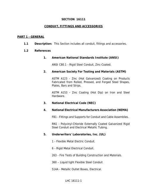
<strong>SECTION</strong> <strong>16111</strong><br />
<strong>CONDUIT</strong>, <strong>FITTINGS</strong> <strong>AND</strong> ACCESSORIES<br />
PART 1 - GENERAL<br />
1.1 Description: This Section includes all conduit, fittings and accessories.<br />
1.2 References<br />
1. American National Standards Institute (ANSI)<br />
ANSI C80.1 - Rigid Steel Conduit, Zinc-Coated.<br />
2. American Society For Testing and Materials (ASTM)<br />
ASTM A123 - Zinc (Hot Galvanized) Coating on Products<br />
Fabricated from Rolled, Pressed, and Forged Steel Shapes,<br />
Plates, Bars and Strips.<br />
ASTM A153 - Zinc Coating (Hot Dip) on Iron and Steel<br />
Hardware.<br />
3. National Electrical Code (NEC)<br />
4. National Electrical Manufacturers Association (NEMA)<br />
FB1 - Fittings and Supports for Conduit and Cable Assemblies.<br />
RN1 - Polyvinyl-Chloride Externally Coated Galvanized Rigid<br />
Steel Conduit and Electrical Metallic Tubing.<br />
5. Underwriters' Laboratories, Inc. (UL)<br />
1 - Flexible Metal Electric Conduit.<br />
6 - Rigid Metal Electrical Conduit.<br />
263 - Fire Tests of Building Construction and Materials.<br />
360 – Liquid tight Flexible Steel Conduit<br />
514A - Metallic Outlet Boxes, Electrical.<br />
<strong>LHC</strong> <strong>16111</strong>-1
1.3 Submittals<br />
PART 2 - MATERIALS<br />
514B - Fittings for conduit and Outlet Boxes.<br />
514C - Nonmetallic Outlet Boxes, Flush Device Boxes and<br />
Covers.<br />
6. Steel Structures Painting Council (SSPC)<br />
SP3 - Power Tool Cleaning.<br />
SP11 - Power Tool Cleaning to Bare Metal.<br />
7. All electrical and control equipment and material shall bear the<br />
recognized Underwriters Laboratories, Inc. (UL) seal of<br />
approval. It is Vendor’s responsibility to obtain local inspection<br />
approval for all non-UL labeled equipment and pay all fees in<br />
connection with the same.<br />
. Submit as specified in <strong>SECTION</strong> 1330.<br />
2.1 Acceptable Manufacturers<br />
A. Rigid Steel Conduit<br />
1. Allied Tube and Conduit Corporation.<br />
2. LTV Steel.<br />
B. Rigid Steel Conduit with Bonded Polyvinyl Chloride (PVC)<br />
Jacket<br />
1. OCAL Inc.<br />
2. Robroy Industries.<br />
3. Perma-Cote Industries.<br />
C. Liquid-tight: Flexible Metal Conduit:<br />
1. Anamet, Inc.<br />
<strong>LHC</strong> <strong>16111</strong>-2
2. Electri-Flex Company.<br />
D. Rigid Polyvinyl Chloride (PVC) Conduit<br />
1. Kraloy Plastic Pipe Company.<br />
2. Certain-Teed Products Corporation.<br />
3. Caron Products Division, Continental Oil Company.<br />
E. Rigid Steel Conduit Fittings<br />
1. Heavy-duty Cast Malleable Iron Fittings<br />
a. Appleton Electric Company.<br />
b. Crouse Hinds Company.<br />
2. Conduit Expansion and Deflection Fittings<br />
a. O-Z /Gedney Company.<br />
F. Rigid Steel Conduit Boxes<br />
1. Indoor and Outdoor Boxes<br />
a. Hoffman Engineering Company of Anoka, Minnesota.<br />
2. Conduit Hubs<br />
a. Appleton Electric Company.<br />
b. Myers Industries, Inc. (ITT).<br />
c. Crouse-Hinds Company.<br />
d. O-Z /Gedney Company.<br />
G. Supports<br />
1. B-Line Company.<br />
2. Midland-Ross Corporation.<br />
<strong>LHC</strong> <strong>16111</strong>-3
3. Unistrut Products Corporation.<br />
4. U.S. Gypsum Company.<br />
5. Van-Huffel Tube Corporation.<br />
H. Wall Entrance Seals<br />
1. O-Z/Gedney Company.<br />
I. Explosion-proof Fittings<br />
1. Crouse-Hinds Company<br />
2. Appleton Electric Company<br />
J. Fire-stopping Materials<br />
1. 3M, (Minnesota Mining and Manufacturing Company)<br />
2. Thomas and Betts<br />
3. Hilti<br />
4. Dow Corning<br />
K. Duct Seal<br />
1. Ideal Industries<br />
2. 3M, (Minnesota Mining and Manufacturing Company)<br />
2.2 Design Requirements<br />
A. Each length of threaded conduit furnished with coupling on one end<br />
and metal or plastic thread protector on other end.<br />
B. UL listed and labeled conduit, on each length, fittings and<br />
accessories.<br />
C. Sizes of conduit, fittings and accessories as indicated, specified or as<br />
required by Electrical Codes and Standards.<br />
D. Provide and meet the requirements of the following sections for the<br />
conduit, fittings and accessories indicated.<br />
<strong>LHC</strong> <strong>16111</strong>-4
2.3 Rigid Steel Conduit<br />
A. Conform to ANSI C80.1 and UL-6.<br />
B. Mild ductile steel, circular in cross section with uniform wall thickness<br />
sufficiently accurate to cut clean threads.<br />
C. Each length threaded on both ends with threads protected.<br />
D. All scale, grease, dirt, burrs and other foreign matter removed from<br />
inside and outside prior to application of coating materials.<br />
E. Galvanized by the hot-dip process as follows:<br />
1. Interior and exterior surfaces coated with a solid, unbroken<br />
layer of 99% virgin zinc by dipping.<br />
2. Coating not to show fixed deposits of copper after four 1-<br />
minute immersions in a standard copper sulfate solution.<br />
3. One coat of zinc chromate finish on inside and outside surfaces<br />
to prevent oxidation and white rust.<br />
F. Couplings and elbows fabricated, coated and finished by the same<br />
process as conduit.<br />
2.4 Rigid Steel Conduit and Fittings with Bonded Polyvinyl Chloride<br />
(PVC) Jacket<br />
A. Conform to hot-dipped galvanized rigid steel conduit as specified in<br />
NEMA-RN1, RIGID STEEL <strong>CONDUIT</strong>, this Section, and as follows.<br />
B. Prior to application of PVC coating, clean interior and exterior surfaces<br />
to remove contaminates to provide a suitable surface for bonding.<br />
C. Bond the PVC coating to the conduit. Extruded PVC jackets are<br />
unacceptable.<br />
D. Coated externally with PVC to a nominal 40 mils, 0.035-inch to<br />
0.045-inch.<br />
E. Uniformly coat around outside diameter and full length of the<br />
conduit.<br />
<strong>LHC</strong> <strong>16111</strong>-5
F. Coat the prethreaded ends with a urethane coating having a nominal<br />
thickness of 2 mils (0.002-inch).<br />
G. Coat the interior surfaces of all conduits and feed-through fittings<br />
(except where prohibited by design) with a two-part, chemically<br />
cured, urethane coating having a nominal thickness of 2 mils (0.002-<br />
inch).<br />
H. Exceed the tensile strength of coating with bond between metal and<br />
jacket.<br />
I. Couplings, elbows, and other conduit fittings, boxes, cover-plates,<br />
supports, hardware and related items shall be treated and coated with<br />
the same process as conduit.<br />
J. Each coupling and fitting shall include a PVC sleeve that overlaps the<br />
conduit.<br />
K. Length of the overlapping sleeve equals diameter of the conduit or 2<br />
inches, whichever is least.<br />
L. Final cured PVC coating capable of withstanding a minimum electrical<br />
potential of 2000V.<br />
M. All conduit accessories, clamps, and hardware that are uncoated shall<br />
be stainless steel.<br />
2.5 Liquid-Tight Flexible Metal Conduit<br />
A. Conform to UL-360.<br />
B. Liquid-tight conduit with flexible galvanized-steel core and a synthetic<br />
rubber, polyvinyl chloride, or thermoplastic covering.<br />
C. Spiral encased copper bonding conductors for conduit in sizes 1-1/4<br />
inches and smaller.<br />
D. External grounding jumper as required.<br />
E. Polyvinyl chloride (PVC) jacket, Type HA or Type O.R. "Seal-Tite" for<br />
oil-resistant applications.<br />
2.6 Rigid Polyvinyl Chloride (PVC) Conduit<br />
<strong>LHC</strong> <strong>16111</strong>-6
A. Fabricated from self-extinguishing high-impact polyvinyl chloride<br />
designed for aboveground and underground installations.<br />
B. Type EPC Schedule 80 heavy-wall rigid conduit.<br />
C. Fittings and accessories fabricated from same materials as conduit.<br />
D. Solvent-cement-type joints as recommended by manufacturer.<br />
2.7 Rigid Steel Fittings<br />
A. Heavy-Duty Cast Malleable Iron Fittings<br />
1. Mogul type for conduit sizes 1-1/2 inches and larger.<br />
2. LBD or roller action type LB for right angle fittings for conduit<br />
sizes 2 inches and larger.<br />
3. Full-threaded hubs and rubber-gasketed covers.<br />
4. Zinc, cadmium-plated or bronze hardware bolts and screws for<br />
assembly.<br />
5. Finish with cadmium-plated or galvanizing.<br />
6. Standard and junction fittings.<br />
B. Conduit Expansion Fittings<br />
1. Line of Conduit Type<br />
a. Galvanized expansion fittings for rigid conduit<br />
movement up to 4 inches.<br />
b. Insulated metal bushing on ends of the conduit,<br />
bonding jumper, and with expansion head sealed with a<br />
high-grade graphite packing.<br />
c. O-Z/Gedney Company, Type AX with Type AJ bonding<br />
jumper or Thomas and Betts Corporation, Type XJG.<br />
2. End Type<br />
a. For conduit terminating in a junction box.<br />
<strong>LHC</strong> <strong>16111</strong>-7
. O-Z/Gedney Company, Type EXE with Type BJ-E<br />
bonding jumper.<br />
C. Conduit Expansion and Deflection Fittings<br />
1. Provide for movement of 3/4-inch from normal in all directions<br />
between two rigid conduits.<br />
2. Integral bonding jumper.<br />
3. O-Z/Gedney Company, Type DX.<br />
D. Conduit Wall Entrance Seals<br />
1. Provide where required or indicated.<br />
2. O-Z/Gedney Company Type FSK.<br />
E. Conform to NEMA Type 3R enclosure in all nonhazardous areas except<br />
as specified or indicated otherwise.<br />
2.8 Fittings, Couplings and Boxes for Rigid Steel Conduit<br />
A. Fittings<br />
1. Explosion-proof or weather-proof as specified.<br />
2. Cast malleable iron.<br />
3. Threaded cover to conform to NEC.<br />
4. Full thread hubs.<br />
5. Seal compound well for seal.<br />
6. Drain seals as indicated or required to provide a continuous<br />
automatic drain of water.<br />
7. Chico compound for all sealing fittings.<br />
8. PVC jacketed in corrosive areas and where indicated.<br />
B. Couplings<br />
<strong>LHC</strong> <strong>16111</strong>-8
1. Explosion-proof or weather-proof as specified.<br />
2. Flexible.<br />
3. Conform to NEC.<br />
4. Threaded, steel or bronze end fittings securely fastened to the<br />
core and braided to ensure electrical continuity.<br />
5. Vinyl plastic coating in severely corrosive locations as indicated.<br />
2.9 Rigid Steel Conduit Boxes<br />
A. Indoor Boxes<br />
1. Hot-dipped galvanized steel.<br />
2. Galvanized steel covers.<br />
2. For special boxes where it is not possible to provide hot-dip<br />
galvanizing, apply organic zinc-rich primer at 3 mils dry film<br />
thickness after SSPC-SP3 Power Tool Cleaning.<br />
3. Minimum gage requirements:<br />
No surface<br />
area exceeds<br />
No single<br />
dimension<br />
exceeds<br />
Steel Gage<br />
1000 sq in. 40 in. 14<br />
1500 sq in. 60 in. 12<br />
over 1500 sq in. over 60 in. 10<br />
4. Explosion-proof or weather-proof as specified.<br />
5. Threaded conduit entrances or rigid conduit hubs on all boxes.<br />
6. Include piano-hinged, gasketed cover, and interior mounting<br />
panel when used for enclosing terminal blocks and control<br />
relays.<br />
<strong>LHC</strong> <strong>16111</strong>-9
9. Oiltight JIC boxes modified for NEMA Type 3R or Type 4<br />
enclosure for non-explosion-proof areas.<br />
B. Outdoor Boxes<br />
1. 11-gauge minimum galvanized steel with drip lip and<br />
galvanized-steel covers fastened with bronze or cadmiumplated<br />
screws or bolts, or cast iron with galvanized finish and<br />
flanged bolted covers.<br />
2. For special boxes where it is not possible to provide hot-dip<br />
galvanizing, apply organic zinc-rich primer at 3 mils dry film<br />
thickness after SSPC-SP3 Power Tool Cleaning.<br />
3. Threaded conduit entrances or rigid conduit hubs on all boxes.<br />
4. Rubber or neoprene gasket for cover.<br />
5. Explosion-proof or weather-proof as specified. Conform to<br />
NEMA Type 3R enclosure for non-explosion-proof applications<br />
in all outdoor installations unless indicated otherwise.<br />
6. Include piano-hinged, gasketed cover, and interior mounting<br />
panel when used for enclosing terminal blocks and control<br />
relays.<br />
7. Oiltight JIC boxes modified for NEMA Type 3R or Type 4<br />
enclosure in non-explosion-proof applications.<br />
B. Metallic Barriers<br />
1. Designed not to separate phases of a power circuit.<br />
2. Provide as indicated for the isolation of power circuits from<br />
other type circuits.<br />
C. Box size as required, or as indicated, for each particular installation.<br />
D. Include provisions for mounting cable supports where indicated,<br />
specified or as required by NEC.<br />
E. Provide as required for cable pulling, junctions, terminals, and for<br />
mounting of switches, outlets and control devices.<br />
<strong>LHC</strong> <strong>16111</strong>-10
2.10 Support System<br />
A. Fabricated from structural steel or manufactured framing members<br />
equal to "Unistrut" P-3000 series as manufactured by Unistrut<br />
Corporation.<br />
B. Minimum 12 gage.<br />
C. Construct as required to rigidly support all conduit runs and boxes.<br />
D. Hot-dip galvanized steel conduit clamps or stainless steel, sized for<br />
the specific conduit size, to support all exposed metallic conduit.<br />
E. Nonmagnetic clamps to support nonmetallic conduits.<br />
F. Provide stainless steel rods, anchors, inserts, bolts, washer, and nuts.<br />
G. Materials shall be compatible with the equipment supported.<br />
H. Manufactured Framing Members<br />
1. Wet Locations<br />
2.11 Fire-stopping and Duct Seal<br />
A. Fire-stopping<br />
a. Channel hot-dipped galvanized after all manufacturing<br />
operations are completed.<br />
b. Galvanizing zinc weight of 2 ounces per square foot on<br />
surface to conform to ASTM A123 and ASTM A153.<br />
1. Weather-resistant silicone sealant.<br />
2. Provide 4-hour fire rating.<br />
3. UL tested system.<br />
B. Duct Seal<br />
1. Non-corrosive, permanently soft compound.<br />
2. Nontoxic.<br />
<strong>LHC</strong> <strong>16111</strong>-11
3. Provide flexible re-enterable and repairable seal around cables in<br />
conduit.<br />
4. Prevent air movement and drafts through conduits.<br />
5.<br />
PART 3 - EXECUTION<br />
3.1 Preparation<br />
A. Provide suitable protection for conduit risers against damage during<br />
construction.<br />
B. Cap ends of all conduits before concrete is poured.<br />
C. Cap all conduits and provide pullstring after cleaning where conduits<br />
are to be left empty by this contract.<br />
D. Carefully ream ends of all conduit lengths after cutting to eliminate<br />
sharp burrs.<br />
E. Clean out all conduit before pulling wire.<br />
F. Clean out all conduits immediately after concrete work is finished.<br />
3.2 Installation<br />
A. General Requirements<br />
1. Location<br />
a. Install conduit as near as possible to the routing<br />
indicated.<br />
b. Shift locations as required to avoid interference with<br />
other equipment and piping being installed.<br />
c. Where routing of conduit is not indicated, such as for<br />
lighting home run circuits and other systems requiring<br />
small conduit runs, route conduit as specified subject to<br />
approval by Engineer.<br />
<strong>LHC</strong> <strong>16111</strong>-12
2. Do not use conduit in sizes smaller than 3/4-inch, except 1/2-<br />
inch may be used for connections to control devices and<br />
thermocouples where necessary.<br />
3. Holes and Sleeves<br />
a. Provide through floors, walls and roofs as necessary for<br />
conduit runs, including approved flashing and weather<br />
proofing at outside walls and on roofs.<br />
b. Install sleeves or forms for all openings in new work.<br />
c. Provide the required inserts and holes, completely<br />
sleeved, bonded, curbed, flashed and finished off in an<br />
approved manner, whether in concrete, steel grating,<br />
metal panels or roofs.<br />
d. Core-drill all holes required in existing building work<br />
using a dustless method.<br />
e. Place nonshrinking grout or Dow Corning 3-6548<br />
Silicone RTV (or equivalent General Electric RTF 762)<br />
foam as specified, in the following locations:<br />
(1) All holes in concrete, walls, floor and roof slabs<br />
after installation of conduit.<br />
(2) All unused holes and sleeves as approved by<br />
Engineer.<br />
f. Install wall entrance seals where conduit enters the<br />
building or vaults from exterior underground.<br />
g. Install fire-stopping at all conduit penetration of fire<br />
rated walls, ceilings and floors. Fire-stopping shall<br />
equal or exceed the fire rating of the wall, ceiling or<br />
floor in which it is installed.<br />
4. Make connections to boxes, panels, and other equipment as<br />
follows:<br />
a. For Indoor Dry Locations: Double locknuts, one<br />
inside and one outside.<br />
<strong>LHC</strong> <strong>16111</strong>-13
. For Outdoor and Damp Locations: Rigid weatherproof<br />
conduit hubs.<br />
c. For Explosion-proof Locations: Use conduit<br />
connector seals approved for the hazardous location<br />
specified.<br />
d. Bushings<br />
(1) Threaded malleable iron or steel.<br />
(2) Insulated with Bakelite, molded and bonded into<br />
the bushing.<br />
(3) Placed on end of conduit in addition to locknuts.<br />
(4) Install with integral grounding connector and<br />
conductor where all conduits pass through<br />
multiple concentric panel knockouts and where<br />
the conduit must be bonded to equipment it is<br />
not attached to.<br />
e. Install duct seal in conduits around cables in nonhazardous<br />
locations at all conduit terminations at<br />
control panels and boxes containing terminations and<br />
splices.<br />
5. Running threads will not be permitted.<br />
6. Coat all field cut threads in galvanized conduit with aluminum<br />
paint.<br />
7. Comply with applicable requirements of NEC pertaining to<br />
installation of conduit systems.<br />
8. Place drainage fittings or weep holes at unavoidable low points<br />
where moisture can collect.<br />
9. Install an entire conduit system that is electrically continuous<br />
with bonding jumpers provided as necessary to conform to<br />
NEC.<br />
10. Install expansion fittings at all building expansion joints and<br />
every 100 feet of continuous conduit.<br />
<strong>LHC</strong> <strong>16111</strong>-14
11. Provide all spare or empty conduits with pullstrings for future<br />
use.<br />
B. Rigid Steel Conduit<br />
1. Exposed<br />
a. Install where specified or indicated on drawings.<br />
b. Install above grade outdoors.<br />
c. Install horizontal runs as high above floor as possible<br />
and in no case lower than 7 feet above floor, walkway<br />
or platforms in passage areas.<br />
d. Run conduit parallel or perpendicular to walls, ceiling,<br />
beams, and columns unless indicated otherwise.<br />
e. Route to clear all doors, windows, access wells, and<br />
openings.<br />
f. Group parallel runs in neatly aligned banks where<br />
possible with minimum of 1-inch clearance between<br />
conduits.<br />
g. Maintain 6-inch clearance between conduit and<br />
coverings on all hot lines; steam, hot water, etc.<br />
h. Do not exceed a distance of 8 feet between supports on<br />
horizontal or vertical runs.<br />
i. When terminating at cable tray, attach conduit to tray<br />
and electrically bond conduit with ground wire to the<br />
cable tray. Install duct seal in conduits around cables to<br />
prevent ingress of water.<br />
2. Concealed<br />
a. Conceal conduit for lighting, convenience outlets, and<br />
other circuits in walls, ceiling and floors where possible.<br />
b. Do not install conduit in concrete where conduit outside<br />
diameter exceeds one-third of concrete thickness.<br />
<strong>LHC</strong> <strong>16111</strong>-15
c. Install parallel runs with a minimum spacing of three<br />
conduit diameters between conduits.<br />
d. Use expansion and deflection fitting with bonding<br />
jumpers at all concrete expansion joints.<br />
e. Tie securely in place to prevent movement when<br />
concrete is poured.<br />
f. Install in floor slabs in as straight a run as possible.<br />
Conduit crossovers are not permitted unless conduit<br />
total outside diameter is one-third of the concrete<br />
thickness or less.<br />
g. Use long radius elbows except on risers where curved<br />
portion of elbow would extend above the finished floor<br />
or foundation.<br />
h. Make all joints watertight after installation by coating all<br />
finished joints with coal tar solution applied at 15 mils<br />
minimum dry film.<br />
3. Buried<br />
(1) Kop-Coat - No. 50.<br />
(2) Tnemec - 46-449.<br />
a. Place where indicated.<br />
b. Use PVC jacketed conduit or rigid PVC Schedule 80 as<br />
indicated.<br />
c. Make all joints watertight by field-applied coat of vinyl<br />
plastic compound or PVC welding solution furnished by<br />
the conduit manufacturer.<br />
d. Use bender one size larger for conduit sized 1 inch or<br />
less and conventional bender for conduit sized above 1<br />
inch.<br />
<strong>LHC</strong> <strong>16111</strong>-16
e. Use strap wrench to tighten conduit. Repair damaged<br />
coating with liquid patching compound recommended<br />
by conduit manufacturer.<br />
f. Install in as straight a run as possible between<br />
termination points of exact routing to be determined in<br />
the field and subject to approval by Engineer.<br />
g. Bury conduits a minimum of 24 inches (to top of<br />
conduit) below finish grade unless indicated otherwise<br />
or required by code.<br />
h. Slope conduit away from conduit risers where possible.<br />
i. Maintain 6-inch separation from underground piping.<br />
j. Use long radius bends at all risers unless indicated<br />
otherwise.<br />
k. After trench bottom has been finished to grade, lay<br />
conduit. Backfilling shall be as specified in DIVISION<br />
2.<br />
l. Cap ends of all conduit risers before backfilling.<br />
m. Provide watertight seal around wires where conduit<br />
terminates in pull box.<br />
n. Use PVC coated rigid galvanized steel conduit when<br />
making transitions from buried to above ground conduit<br />
runs.<br />
C. Liquid-Tight Flexible Metal Conduit<br />
1. Use between rigid conduit and motor terminal boxes except<br />
where conduit runs down from above and cannot be<br />
conveniently supported by a floor flange.<br />
2. Place between rigid conduit or conduit box and control device<br />
cases where direct connection is not desirable for reasons of<br />
equipment movement, vibration, or for ease of maintenance.<br />
3. Install at all points of connection to equipment mounted on<br />
supports to allow for expansion and contraction.<br />
<strong>LHC</strong> <strong>16111</strong>-17
4. Conform to NEC with installation of conductors.<br />
5. Install at locations where rigid conduit connections are<br />
impractical.<br />
6. Use minimum length consistent with manufacturer's standard<br />
lengths, the acceptable bending radius, and with required<br />
movement of equipment.<br />
7. Maximum length of 3 feet unless otherwise approved by<br />
Engineer.<br />
8. Install an external bonding jumper to conform to NEC on<br />
conduit sized 1-1/2 inches and larger.<br />
D. Flexible Metal Conduit<br />
1. Use between rigid conduit and devices, except in hazardous<br />
areas and areas subject to dampness, water, and corrosive<br />
fumes. Do not use with vapor-tight fixtures. Use in<br />
accordance with the National Electrical Code Article 350.<br />
2. Use in lieu of direct connection of rigid conduit where it is not<br />
desirable for reasons of equipment movement, vibration, or for<br />
ease of maintenance.<br />
3. Install as required for expansion and contraction.<br />
4. Use minimum length consistent with manufacturers’ standard<br />
lengths, the acceptable bending radius, and with required<br />
movement of equipment.<br />
5. Maximum length of 3 feet unless otherwise approved by<br />
Engineer.<br />
6. Install in sizes smaller than 3 inches.<br />
7. Install an external bonding jumper to conform to the National<br />
Electrical Code on conduit sized 1-1/2 inches and larger.<br />
E. Conduit Fittings<br />
1. Installations of special fittings as required.<br />
<strong>LHC</strong> <strong>16111</strong>-18
2. All materials shall be compatible.<br />
3. Install as required.<br />
F. Boxes<br />
1. Install special boxes as indicated of size required for conduits<br />
and cables entering and leaving box.<br />
2. Install where required for pull or junction boxes and for<br />
mounting or connecting to switches, outlets, intermediate<br />
terminal blocks or control devices.<br />
3. Provide 1/4-inch weep holes in interior boxes where conduits<br />
enter from exterior or buried installation.<br />
G. Supports<br />
1. Construct with sufficient rigidity to hold all mounted equipment<br />
and material in permanent and neat alignment.<br />
2. Design to provide 1/4-inch space between equipment housings<br />
and walls or columns upon which they are mounted.<br />
3. Do not exceed load requirements in NEC and NEMA standards.<br />
4. After Power Tool Cleaning SSPC-SP11, paint all welds, field<br />
cuts and damaged areas with organic zinc-rich primer at 3 mils<br />
dry film thickness.<br />
a. Ameron - 68HS.<br />
b. Carboline - Carbozinc 858.<br />
c. Porter - Zinc-Lock 308.<br />
d. Tnemec-Tneme Zinc 90-93.<br />
5. Use electrogalvanized steel conduit clamps and nonmagnetic<br />
conduit clamps to support electrogalvanized steel conduit and<br />
nonmagnetic conduit, respectively.<br />
<strong>LHC</strong> <strong>16111</strong>-19
6. Provide stainless steel rods, anchors, inserts, bolts, washers<br />
and nuts.<br />
I. Explosion-proof Fittings<br />
1. Install explosion-proof fittings in the rigid steel conduit system<br />
as required by the NEC.<br />
2. Install necessary fittings where not indicated, but required by<br />
code.<br />
PART 4<br />
MEASUREMENT <strong>AND</strong> PAYMENT<br />
4.1 Measurement<br />
A. No measurement will be made for this item.<br />
4.2 Payment<br />
A. Payment will be made at the contract lump sum price bid and shall be<br />
considered full payment for providing labor and materials to perform<br />
this work.<br />
** END OF <strong>SECTION</strong> <strong>16111</strong> **<br />
<strong>LHC</strong> <strong>16111</strong>-20


