FIBRE CHANNEL - T11
FIBRE CHANNEL - T11
FIBRE CHANNEL - T11

Create successful ePaper yourself
Turn your PDF publications into a flip-book with our unique Google optimized e-Paper software.
Copies of this document may be purchased from: August 7, 1998<br />
Global Engineering, 15 Inverness Way East, NCITS TR-xx/Project 1315-DT/Rev 1.07<br />
Englewood, CO 80112-5704<br />
Phone: (800) 854-7179 or (303) 792-2181 Fax: (303) 792-2192<br />
<strong>FIBRE</strong> <strong>CHANNEL</strong><br />
TAPE (FC-TAPE)<br />
<strong>T11</strong>/98-124v8<br />
REV 1.07<br />
NCITS working draft proposed<br />
Technical Report<br />
August 7, 1998<br />
Secretariat:<br />
Information Technology Industry Council<br />
ABSTRACT:<br />
NOTE:<br />
This is a draft proposed Technical Report of Accredited Standards Committee NCITS. As such, this<br />
is not a completed report. The <strong>T11</strong> Technical Committee may modify this document as a result of<br />
comments received during public review and its approval as a technical report.<br />
POINTS OF CONTACT:<br />
Rich Taborek (<strong>T11</strong>.3 Chairman)<br />
G2 Networks, Inc.<br />
16780 Lark Avenue<br />
Los Gatos, CA 95032-7646<br />
Phone: (408) 399-3867<br />
Fax: (408) 399-3899<br />
EMail: rtaborek@g2networks.com<br />
Jeffrey Stai (<strong>T11</strong>.3 Vice Chairman)<br />
Brocade Communications Systems, Inc.<br />
15707 Rockfield Boulevard, Suite 215<br />
Irvine, CA 92618<br />
Phone: (714) 455-2908<br />
Fax: (714) 455-9287<br />
E-Mail: stai@brocadecomm.com<br />
Dale LaFollette<br />
(Fibre Channel Tape Facilitator)<br />
StorageTek<br />
2270 South 88th Street<br />
Louisville, CO 80028-4223<br />
Phone: (303) 673-8791<br />
Fax: (303) 673-2568<br />
E-Mail: dale_lafollette@stortek.com<br />
David A. Peterson<br />
(Fibre Channel Tape Technical Editor)<br />
StorageTek Network Systems Group<br />
7600 Boone Avenue North<br />
Brooklyn Park, MN 55428<br />
Phone: (612) 391-1008<br />
Fax: (612) 391-1095<br />
E-mail: dap@network.com
Editor’s Note: Release 1.00 Initial Document Differences from PLDA<br />
– Addresses only streaming and media changer device’s<br />
– Data Overlay Allowed (for sequence retransmission)<br />
– Error Detection and Recovery Procedure with new ELS’s added (REC/SRR)<br />
– FCP_CONF implementation and usage<br />
Editor’s Note: Release 1.01 Changes/Additions<br />
– Update of Annex H<br />
– Added Media Changer SCSI command table<br />
– Added diagrams to Annex G<br />
Editor’s Note: Release 1.02 Changes/Additions<br />
– Added FCP_TOV<br />
– Incorporated changes discussed in March-98 FC-Tape working group.<br />
– Added section describing Class 2-Public Loop operation<br />
Editor’s Note: Release 1.03 Changes/Additions<br />
– Updated section 8 (SCSI FCP Feature Set)<br />
– Added changes from comments received<br />
– Updated PLOGI and FLOGI tables<br />
Editor’s Note: Release 1.04a Changes/Additions<br />
– Added changes from comments received<br />
– Added FCP Command Reference Number text<br />
– Added SRR to Class 2 error recovery<br />
– Moved Class 2 diagrams to annex<br />
– Collapsed FCP Error Detection and Recovery (Class 2 and Class 3)<br />
– Added Fibre Channel Mode Page 0x19 to annex<br />
Editor’s Note: Release 1.05 Changes/Additions<br />
– Removed clause 10.<br />
– Combined error detection and recovery procedures into one annex (Class 2 and Class 3).<br />
– Updated Public and Private loop behavior.<br />
– Updated clause 9.<br />
– Removed annex D (RR_TOV proposal).<br />
Editor’s Note: Release 1.06b Changes/Additions<br />
– Changed error detection and recovery diagrams.<br />
– Added notes and device reservations to Table 23.
Editor’s Note: Release 1.07 Changes/Additions<br />
– Moved document towards Public loop operation.<br />
– Changed SRR ladder diagram.<br />
– Added ABTS changes text (to be expanded on).
ANSI ®<br />
NCITS TR-xx<br />
draft proposed NCITS Technical Report<br />
Fibre Channel —<br />
Tape (FC-TAPE)<br />
Secretariat<br />
Information Technology Industry Council<br />
Approved ,199<br />
American National Standards Institute, Inc.<br />
Abstract<br />
This profile selects and restricts logical options from the Fibre Channel Physical and Signalling, Fibre<br />
Channel Protocol for SCSI, Fibre Channel Arbitrated Loop, and Small Computer Systems Interface standards,<br />
such that any device complying with the profile should interoperate.<br />
iv
NCITS<br />
<strong>T11</strong><br />
Technical<br />
Report<br />
Series<br />
This Technical Report is one in a series produced by the American National<br />
Standards Committee, NCITS, Information Technology. The secretariat for NCITS<br />
is held by the Computer and Business Equipment Manufacturers Association<br />
(CBEMA), 1250 Eye Street, NW Suite 200, Washington DC 20005.<br />
As a by-product of the standards development process and the resources of<br />
knowledge devoted to it, NCITS from time to time produces Technical Reports.<br />
Such Technical Reports are not standards, nor are they intended to be used as<br />
such.<br />
Patent<br />
Statement<br />
NCITS Technical Reports are produced in some cases to disseminate the<br />
technical and logical concepts reflected in standards already published or under<br />
development. In other cases, they derive from studies in areas where it is found<br />
premature to develop a standard due to a still changing technology, or<br />
inappropriate to develop a rigorous standard due to the existence of a number of<br />
viable options, the choice of which depends on the user's particular requirements.<br />
These Technical Reports, thus, provide guidelines, the use of which can result in<br />
greater consistency and coherence of information processing systems.<br />
When the draft Technical Report is completed, the Technical Committee approval<br />
process is the same as for a draft standard. Processing by NCITS is also similar to<br />
that for a draft standard.<br />
CAUTION: The developers of this Technical Report have requested that holder's<br />
of patents that may be required for the implementation of the Technical Report,<br />
disclose such patents to the publisher. However, neither the developers nor the<br />
publisher have undertaken a patent search in order to identify which, if any, patents<br />
may apply to this Technical Report.<br />
As of the date of publication of this Technical Report and following calls for the<br />
identification of patents that may be required for the implementation of the<br />
Technical Report, no such claims have been made. No further patent search is<br />
conducted by the developer or the publisher in respect to any Technical Report it<br />
processes. No representation is made or implied that licenses are not required to<br />
avoid infringement in the use of this Technical Report.<br />
Published by<br />
American National Standards Institute<br />
11 W. 42nd Street, New York, New York 10036<br />
Copyright © 199x by American National Standards Institute<br />
All rights reserved<br />
No part of this publication may be reproduced in any<br />
form, in an electronic retrieval system or otherwise,<br />
without prior written permission of the publisher.<br />
Printed in the United States of America<br />
v
NCITS TR-xx Fibre Channel Tape Rev 1.07 August 7, 1998<br />
Table of Contents<br />
1 Introduction and scope . . . . . . . . . . . . . . . . . . . . . . . . . . . . . . . . . . . . . . . . . . . . . . . . . 1<br />
2 Normative references . . . . . . . . . . . . . . . . . . . . . . . . . . . . . . . . . . . . . . . . . . . . . . . . . . . 2<br />
2.1 Approved references . . . . . . . . . . . . . . . . . . . . . . . . . . . . . . . . . . . . . . . . . . . . . . . . . 2<br />
2.2 References under development . . . . . . . . . . . . . . . . . . . . . . . . . . . . . . . . . . . . . . . . . 2<br />
2.3 Other references . . . . . . . . . . . . . . . . . . . . . . . . . . . . . . . . . . . . . . . . . . . . . . . . . . . . 3<br />
3 Definitions and conventions . . . . . . . . . . . . . . . . . . . . . . . . . . . . . . . . . . . . . . . . . . . . . 4<br />
3.1 Definitions . . . . . . . . . . . . . . . . . . . . . . . . . . . . . . . . . . . . . . . . . . . . . . . . . . . . . . . . . 4<br />
3.2 Editorial conventions . . . . . . . . . . . . . . . . . . . . . . . . . . . . . . . . . . . . . . . . . . . . . . . . . 5<br />
3.2.1 Binary notation . . . . . . . . . . . . . . . . . . . . . . . . . . . . . . . . . . . . . . . . . . . . . . . . . . 5<br />
3.2.2 Hexadecimal notation . . . . . . . . . . . . . . . . . . . . . . . . . . . . . . . . . . . . . . . . . . . . . 5<br />
3.3 Abbreviations, acronyms, and symbols . . . . . . . . . . . . . . . . . . . . . . . . . . . . . . . . . . . 6<br />
3.3.1 Acronyms and abbreviations . . . . . . . . . . . . . . . . . . . . . . . . . . . . . . . . . . . . . . . . 6<br />
3.4 Applicability and use of this document . . . . . . . . . . . . . . . . . . . . . . . . . . . . . . . . . . . . 6<br />
3.5 Definitions and abbreviations used in Feature Set tables . . . . . . . . . . . . . . . . . . . . . . 7<br />
4 Structure and Concepts . . . . . . . . . . . . . . . . . . . . . . . . . . . . . . . . . . . . . . . . . . . . . . . . . 9<br />
4.1 Public and Private Loop Behavior . . . . . . . . . . . . . . . . . . . . . . . . . . . . . . . . . . . . . . . 9<br />
5 FC-2 feature sets . . . . . . . . . . . . . . . . . . . . . . . . . . . . . . . . . . . . . . . . . . . . . . . . . . . . . 11<br />
5.1 Node and port naming . . . . . . . . . . . . . . . . . . . . . . . . . . . . . . . . . . . . . . . . . . . . . . . 11<br />
5.2 FLOGI and PLOGI features and parameters for NL_Ports . . . . . . . . . . . . . . . . . . . . 13<br />
5.3 NL_Port and N_Port Common Service Parameters (PLOGI) . . . . . . . . . . . . . . . . . . 14<br />
5.4 NL_Port Common Service Parameters (FLOGI) . . . . . . . . . . . . . . . . . . . . . . . . . . . . 15<br />
5.5 NL_Port and N_Port Class 2 Service Parameters (PLOGI) . . . . . . . . . . . . . . . . . . . . 16<br />
5.6 NL_Port Class 2 Service Parameters (FLOGI) . . . . . . . . . . . . . . . . . . . . . . . . . . . . . 17<br />
5.7 NL_Port and N_Port Class 3 Service Parameters (PLOGI) . . . . . . . . . . . . . . . . . . . . 18<br />
5.8 NL_Port Class 3 Service Parameters (FLOGI) . . . . . . . . . . . . . . . . . . . . . . . . . . . . . 19<br />
5.9 Other FC-2 features . . . . . . . . . . . . . . . . . . . . . . . . . . . . . . . . . . . . . . . . . . . . . . . . . 20<br />
vii
NCITS TR-xx Fibre Channel Tape Rev 1.07 August 7, 1998<br />
5.10 Basic Link Service commands . . . . . . . . . . . . . . . . . . . . . . . . . . . . . . . . . . . . . . . . 21<br />
5.11 Extended Link Services . . . . . . . . . . . . . . . . . . . . . . . . . . . . . . . . . . . . . . . . . . . . . 21<br />
5.12 Responses to Link Services . . . . . . . . . . . . . . . . . . . . . . . . . . . . . . . . . . . . . . . . . . 23<br />
5.13 Exchange and Sequence management . . . . . . . . . . . . . . . . . . . . . . . . . . . . . . . . . 23<br />
5.13.1 Exchange Originator . . . . . . . . . . . . . . . . . . . . . . . . . . . . . . . . . . . . . . . . . . . . 24<br />
5.13.2 Exchange Responder . . . . . . . . . . . . . . . . . . . . . . . . . . . . . . . . . . . . . . . . . . . 24<br />
5.13.3 Sequence management . . . . . . . . . . . . . . . . . . . . . . . . . . . . . . . . . . . . . . . . . . 25<br />
5.13.4 Sequence errors . . . . . . . . . . . . . . . . . . . . . . . . . . . . . . . . . . . . . . . . . . . . . . . 27<br />
6 FC-AL feature set . . . . . . . . . . . . . . . . . . . . . . . . . . . . . . . . . . . . . . . . . . . . . . . . . . . . . 28<br />
6.1 FC-AL features . . . . . . . . . . . . . . . . . . . . . . . . . . . . . . . . . . . . . . . . . . . . . . . . . . . . 28<br />
6.2 Alternate Login_BB_Credit management . . . . . . . . . . . . . . . . . . . . . . . . . . . . . . . . . 29<br />
6.3 Loop Initialization features . . . . . . . . . . . . . . . . . . . . . . . . . . . . . . . . . . . . . . . . . . . . 29<br />
6.3.1 Initializing LIP(F7,F7) and LIP(F7,AL_PS) . . . . . . . . . . . . . . . . . . . . . . . . . . . . . 29<br />
6.3.2 Selective Hard Reset LIP(AL_PD,AL_PS) . . . . . . . . . . . . . . . . . . . . . . . . . . . . . 29<br />
6.3.3 Loop Failure LIP(F8,AL_PS) and LIP(F8,F7) . . . . . . . . . . . . . . . . . . . . . . . . . . . 29<br />
6.3.4 Failure to obtain an AL_PA . . . . . . . . . . . . . . . . . . . . . . . . . . . . . . . . . . . . . . . . 29<br />
7 Timers on Public and Private Loop . . . . . . . . . . . . . . . . . . . . . . . . . . . . . . . . . . . . . . . 31<br />
7.1 Arbitrated Loop Time (AL_TIME) . . . . . . . . . . . . . . . . . . . . . . . . . . . . . . . . . . . . . . . 31<br />
7.2 Loop Initialization Sequence Hold Time (LIS_HOLD_TIME) . . . . . . . . . . . . . . . . . . . 31<br />
7.3 Receiver_Transmitter Timeout (R_T_TOV) . . . . . . . . . . . . . . . . . . . . . . . . . . . . . . . 31<br />
7.4 Error_Detect Timeout (E_D_TOV) . . . . . . . . . . . . . . . . . . . . . . . . . . . . . . . . . . . . . . 31<br />
7.5 Resource Allocation Timeout (R_A_TOV) . . . . . . . . . . . . . . . . . . . . . . . . . . . . . . . . 32<br />
7.6 Resource Recovery Timer (RR_TOV) . . . . . . . . . . . . . . . . . . . . . . . . . . . . . . . . . . . 32<br />
7.7 Fibre Channel Protocol Timeout Value (FCP_TOV) . . . . . . . . . . . . . . . . . . . . . . . . . 33<br />
7.8 Upper Level Protocol Timeout (ULP_TOV) . . . . . . . . . . . . . . . . . . . . . . . . . . . . . . . . 33<br />
8 SCSI-FCP Feature Set . . . . . . . . . . . . . . . . . . . . . . . . . . . . . . . . . . . . . . . . . . . . . . . . . 34<br />
8.1 Process Login parameters . . . . . . . . . . . . . . . . . . . . . . . . . . . . . . . . . . . . . . . . . . . . 34<br />
viii
NCITS TR-xx Fibre Channel Tape Rev 1.07 August 7, 1998<br />
8.2 FCP Information Units . . . . . . . . . . . . . . . . . . . . . . . . . . . . . . . . . . . . . . . . . . . . . . . 35<br />
8.2.1 FCP_CMND IU (T1/T3) . . . . . . . . . . . . . . . . . . . . . . . . . . . . . . . . . . . . . . . . . . . 35<br />
8.2.2 FCP_XFER_RDY IU . . . . . . . . . . . . . . . . . . . . . . . . . . . . . . . . . . . . . . . . . . . . . 36<br />
8.2.3 FCP_DATA IU . . . . . . . . . . . . . . . . . . . . . . . . . . . . . . . . . . . . . . . . . . . . . . . . . . 36<br />
8.2.4 FCP_RSP (I4/I5) . . . . . . . . . . . . . . . . . . . . . . . . . . . . . . . . . . . . . . . . . . . . . . . . 37<br />
8.2.5 FCP_CONF (T12) . . . . . . . . . . . . . . . . . . . . . . . . . . . . . . . . . . . . . . . . . . . . . . . 39<br />
8.3 Task Management Flags and Information Units . . . . . . . . . . . . . . . . . . . . . . . . . . . . 40<br />
8.4 FCP Task Attributes . . . . . . . . . . . . . . . . . . . . . . . . . . . . . . . . . . . . . . . . . . . . . . . . 40<br />
8.5 Other FCP features . . . . . . . . . . . . . . . . . . . . . . . . . . . . . . . . . . . . . . . . . . . . . . . . . 41<br />
8.6 FCP Sequence delivery confirmation in a Class 3 environment . . . . . . . . . . . . . . . . . 41<br />
8.7 FCP Sequence delivery confirmation in a Class 2 environment . . . . . . . . . . . . . . . . . 42<br />
9 FCP Error Detection and Recovery Procedure(s) . . . . . . . . . . . . . . . . . . . . . . . . . . . . 43<br />
9.1 FCP Error Detection for Class 3 Delivery Service . . . . . . . . . . . . . . . . . . . . . . . . . . . 43<br />
9.2 FCP Error Detection for Class 2 Delivery Service . . . . . . . . . . . . . . . . . . . . . . . . . . . 43<br />
9.3 FCP Error Detection and Recovery (Initiator, Class 2 and Class 3) . . . . . . . . . . . . . . 44<br />
9.3.1 Error Detection . . . . . . . . . . . . . . . . . . . . . . . . . . . . . . . . . . . . . . . . . . . . . . . . . 44<br />
9.3.2 FCP_CMND Recovery . . . . . . . . . . . . . . . . . . . . . . . . . . . . . . . . . . . . . . . . . . . 44<br />
9.3.3 FCP_XFER_RDY Recovery . . . . . . . . . . . . . . . . . . . . . . . . . . . . . . . . . . . . . . . 44<br />
9.3.4 FCP_RSP Recovery . . . . . . . . . . . . . . . . . . . . . . . . . . . . . . . . . . . . . . . . . . . . . 45<br />
9.3.5 FCP_DATA Recovery - Write . . . . . . . . . . . . . . . . . . . . . . . . . . . . . . . . . . . . . . 45<br />
9.3.6 FCP_DATA Recovery - Read . . . . . . . . . . . . . . . . . . . . . . . . . . . . . . . . . . . . . . 45<br />
9.3.7 Additional error detection by SCSI Initiator . . . . . . . . . . . . . . . . . . . . . . . . . . . . . 45<br />
9.3.8 Error detection by SCSI Target . . . . . . . . . . . . . . . . . . . . . . . . . . . . . . . . . . . . . 45<br />
9.4 FCP Error Recovery (Target, Class 2) . . . . . . . . . . . . . . . . . . . . . . . . . . . . . . . . . . . 46<br />
9.5 Aborting an Exchange Using ABTS Protocol . . . . . . . . . . . . . . . . . . . . . . . . . . . . . . 46<br />
9.5.1 SCSI Initiator ABTS of Exchange behavior . . . . . . . . . . . . . . . . . . . . . . . . . . . . . 46<br />
9.5.2 SCSI Target ABTS of Exchange behavior . . . . . . . . . . . . . . . . . . . . . . . . . . . . . 47<br />
ix
NCITS TR-xx Fibre Channel Tape Rev 1.07 August 7, 1998<br />
9.5.3 Second-level error recovery . . . . . . . . . . . . . . . . . . . . . . . . . . . . . . . . . . . . . . . . 48<br />
9.5.4 Abort Sequence (ABTS) Frame . . . . . . . . . . . . . . . . . . . . . . . . . . . . . . . . . . . . . 49<br />
9.5.5 Basic Accept (BA_ACC) Frame to ABTS . . . . . . . . . . . . . . . . . . . . . . . . . . . . . . 49<br />
9.5.6 Basic Reject (BA_RJT) Frame to ABTS . . . . . . . . . . . . . . . . . . . . . . . . . . . . . . . 50<br />
9.5.7 Reinstate Recovery Qualifier (RRQ) . . . . . . . . . . . . . . . . . . . . . . . . . . . . . . . . . 50<br />
9.6 SCSI Target error behavior . . . . . . . . . . . . . . . . . . . . . . . . . . . . . . . . . . . . . . . . . . . 50<br />
9.7 Task Management and Multiple-Initiator SCSI Targets . . . . . . . . . . . . . . . . . . . . . . . 51<br />
9.8 SCSI Target Exchange origination capability . . . . . . . . . . . . . . . . . . . . . . . . . . . . . . 51<br />
9.9 Responses to FCP-level Frames before PLOGI or PRLI . . . . . . . . . . . . . . . . . . . . . . 51<br />
10 SCSI features . . . . . . . . . . . . . . . . . . . . . . . . . . . . . . . . . . . . . . . . . . . . . . . . . . . . . . . 52<br />
10.1 Auto Contingent Allegiance (ACA) . . . . . . . . . . . . . . . . . . . . . . . . . . . . . . . . . . . . . 52<br />
10.2 SCSI Status . . . . . . . . . . . . . . . . . . . . . . . . . . . . . . . . . . . . . . . . . . . . . . . . . . . . . . 52<br />
10.3 SCSI Target Discovery . . . . . . . . . . . . . . . . . . . . . . . . . . . . . . . . . . . . . . . . . . . . . 53<br />
10.4 Exchange Authentication following LIP . . . . . . . . . . . . . . . . . . . . . . . . . . . . . . . . . . 54<br />
10.4.1 SCSI Initiator Exchange Authentication . . . . . . . . . . . . . . . . . . . . . . . . . . . . . . 54<br />
10.4.2 SCSI Target Exchange Authentication . . . . . . . . . . . . . . . . . . . . . . . . . . . . . . . 54<br />
10.5 Clearing effects of ULP, FCP, FC-PH, and FC-AL actions . . . . . . . . . . . . . . . . . . . 56<br />
11 SCSI Stream Devices . . . . . . . . . . . . . . . . . . . . . . . . . . . . . . . . . . . . . . . . . . . . . . . . . 58<br />
11.1 Applicable Classes of Service . . . . . . . . . . . . . . . . . . . . . . . . . . . . . . . . . . . . . . . . 58<br />
11.2 Asynchronous Event Notification (AEN) . . . . . . . . . . . . . . . . . . . . . . . . . . . . . . . . . 58<br />
11.3 Command Linking . . . . . . . . . . . . . . . . . . . . . . . . . . . . . . . . . . . . . . . . . . . . . . . . . 58<br />
11.4 Sequential device commands . . . . . . . . . . . . . . . . . . . . . . . . . . . . . . . . . . . . . . . . 58<br />
12 SCSI-3 Media Changer Devices . . . . . . . . . . . . . . . . . . . . . . . . . . . . . . . . . . . . . . . . . 62<br />
12.1 Applicable Classes of Service . . . . . . . . . . . . . . . . . . . . . . . . . . . . . . . . . . . . . . . . 62<br />
12.2 Asynchronous Event Notification (AEN) . . . . . . . . . . . . . . . . . . . . . . . . . . . . . . . . . 62<br />
12.3 Command Linking . . . . . . . . . . . . . . . . . . . . . . . . . . . . . . . . . . . . . . . . . . . . . . . . . 62<br />
12.4 Media Changer Device Commands . . . . . . . . . . . . . . . . . . . . . . . . . . . . . . . . . . . . 62<br />
x
NCITS TR-xx Fibre Channel Tape Rev 1.07 August 7, 1998<br />
Annex A . . . . . . . . . . . . . . . . . . . . . . . . . . . . . . . . . . . . . . . . . . . . . . . . . . . . . . . . . . . . . 65<br />
A.1 Introduction . . . . . . . . . . . . . . . . . . . . . . . . . . . . . . . . . . . . . . . . . . . . . . . . . . . . . . . 65<br />
A.2 Sequence Retransmission Request (SRR) . . . . . . . . . . . . . . . . . . . . . . . . . . . . . . . . 65<br />
A.3 Read Exchange Concise (REC) . . . . . . . . . . . . . . . . . . . . . . . . . . . . . . . . . . . . . . . . 67<br />
A.4 ABTS Changes . . . . . . . . . . . . . . . . . . . . . . . . . . . . . . . . . . . . . . . . . . . . . . . . . . . . 69<br />
Annex B . . . . . . . . . . . . . . . . . . . . . . . . . . . . . . . . . . . . . . . . . . . . . . . . . . . . . . . . . . . . . 71<br />
Annex C . . . . . . . . . . . . . . . . . . . . . . . . . . . . . . . . . . . . . . . . . . . . . . . . . . . . . . . . . . . . . 85<br />
C.1 FCP_CONF Information Unit . . . . . . . . . . . . . . . . . . . . . . . . . . . . . . . . . . . . . . . . . . 85<br />
C.2 FCP_CONF Process Login (PRLI) Parameter . . . . . . . . . . . . . . . . . . . . . . . . . . . . . 85<br />
C.2.1 Word 3, Bit 7: FCP_CONF Support . . . . . . . . . . . . . . . . . . . . . . . . . . . . . . . . . . 85<br />
C.3 FCP_CONF Request Returned in FCP_RSP . . . . . . . . . . . . . . . . . . . . . . . . . . . . . . 85<br />
C.4 FCP_CONF Guidelines . . . . . . . . . . . . . . . . . . . . . . . . . . . . . . . . . . . . . . . . . . . . . . 85<br />
Annex D . . . . . . . . . . . . . . . . . . . . . . . . . . . . . . . . . . . . . . . . . . . . . . . . . . . . . . . . . . . . . 87<br />
D.1 Command Reference Number Process Login (PRLI) Parameter . . . . . . . . . . . . . . . 87<br />
D.1.1 Word 3, Bit 8: Command Reference Number Support (CRNS) . . . . . . . . . . . . . . 87<br />
D.2 FC Mode Page (0x19) Parameter . . . . . . . . . . . . . . . . . . . . . . . . . . . . . . . . . . . . . . 87<br />
D.2.1 Byte 4, Bit 0: Enable Command Reference Number (ECRN) . . . . . . . . . . . . . . . 87<br />
D.3 Guidelines . . . . . . . . . . . . . . . . . . . . . . . . . . . . . . . . . . . . . . . . . . . . . . . . . . . . . . . 87<br />
Annex E . . . . . . . . . . . . . . . . . . . . . . . . . . . . . . . . . . . . . . . . . . . . . . . . . . . . . . . . . . . . . 89<br />
xi
NCITS TR-xx Fibre Channel Tape Rev 1.07 August 7, 1998<br />
xii
NCITS TR-xx Fibre Channel Tape Rev 1.07 August 7, 1998<br />
List of Figures<br />
1. Public and Private NL_Port Coexistence . . . . . . . . . . . . . . . . . . . . . . . . . . . . . . . . . . . . 10<br />
2. FCP Read/Write IU Examples . . . . . . . . . . . . . . . . . . . . . . . . . . . . . . . . . . . . . . . . . . . . 35<br />
3. FCP 8-byte LUN . . . . . . . . . . . . . . . . . . . . . . . . . . . . . . . . . . . . . . . . . . . . . . . . . . . . . . 35<br />
4. ABTS Frame . . . . . . . . . . . . . . . . . . . . . . . . . . . . . . . . . . . . . . . . . . . . . . . . . . . . . . . . . 49<br />
5. BA_ACC Frame to ABTS . . . . . . . . . . . . . . . . . . . . . . . . . . . . . . . . . . . . . . . . . . . . . . . 49<br />
6. BA_RJT Frame to ABTS . . . . . . . . . . . . . . . . . . . . . . . . . . . . . . . . . . . . . . . . . . . . . . . . 50<br />
7. Reinstate Recovery Qualifier . . . . . . . . . . . . . . . . . . . . . . . . . . . . . . . . . . . . . . . . . . . . . 50<br />
8. Lengthy FCP_CMND or Lost ACK . . . . . . . . . . . . . . . . . . . . . . . . . . . . . . . . . . . . . . . . . 71<br />
9. FCP_CMND Lost . . . . . . . . . . . . . . . . . . . . . . . . . . . . . . . . . . . . . . . . . . . . . . . . . . . . . 72<br />
10. FCP_XFER_RDY Lost . . . . . . . . . . . . . . . . . . . . . . . . . . . . . . . . . . . . . . . . . . . . . . . . 73<br />
11. FCP_XFER_RDY Received, ACK Lost (Class 2) . . . . . . . . . . . . . . . . . . . . . . . . . . . . . 74<br />
12. FCP_RSPLost . . . . . . . . . . . . . . . . . . . . . . . . . . . . . . . . . . . . . . . . . . . . . . . . . . . . . . 75<br />
13. FCP_RSP Received, ACK Lost (Class 2) . . . . . . . . . . . . . . . . . . . . . . . . . . . . . . . . . . . 76<br />
14. Lost Write Data, Last Frame of Sequence . . . . . . . . . . . . . . . . . . . . . . . . . . . . . . . . . . 77<br />
15. Lost Write Data, Not Last Frame of Sequence . . . . . . . . . . . . . . . . . . . . . . . . . . . . . . . 78<br />
16. Lost Read Data, Last Frame of Sequence . . . . . . . . . . . . . . . . . . . . . . . . . . . . . . . . . . 79<br />
17. Lost Read Data, Not Last Frame of Sequence . . . . . . . . . . . . . . . . . . . . . . . . . . . . . . . 80<br />
18. ACK Lost on Read (Class 2) . . . . . . . . . . . . . . . . . . . . . . . . . . . . . . . . . . . . . . . . . . . . 81<br />
19. REC or REC Response Lost . . . . . . . . . . . . . . . . . . . . . . . . . . . . . . . . . . . . . . . . . . . . 82<br />
20. SRR or SRR Response Lost . . . . . . . . . . . . . . . . . . . . . . . . . . . . . . . . . . . . . . . . . . . . 83<br />
21. FCP_CONF Example . . . . . . . . . . . . . . . . . . . . . . . . . . . . . . . . . . . . . . . . . . . . . . . . . 86<br />
22. FCP_CONF Lost . . . . . . . . . . . . . . . . . . . . . . . . . . . . . . . . . . . . . . . . . . . . . . . . . . . . . 86<br />
xiii
NCITS TR-xx Fibre Channel Tape Rev 1.07 August 7, 1998<br />
xiv
NCITS TR-xx Fibre Channel Tape Rev 1.07 August 7, 1998<br />
List of Tables<br />
1. Public NL_Port Behavior . . . . . . . . . . . . . . . . . . . . . . . . . . . . . . . . . . . . . . . . . . . . . . . . . 9<br />
2. Private NL_Port Behavior . . . . . . . . . . . . . . . . . . . . . . . . . . . . . . . . . . . . . . . . . . . . . . . . 9<br />
3. PDISC, ADISC, ACC Examples . . . . . . . . . . . . . . . . . . . . . . . . . . . . . . . . . . . . . . . . . . . 11<br />
4. FLOGI and PLOGI features and parameters for NL_Ports . . . . . . . . . . . . . . . . . . . . . . . 13<br />
5. NL_Port and N_Port Common Service Parameters (PLOGI) . . . . . . . . . . . . . . . . . . . . . 14<br />
6. NL_Port and N_Port Common Service Parameters (FLOGI) . . . . . . . . . . . . . . . . . . . . . 15<br />
7. Class 2 Service Parameters (PLOGI) . . . . . . . . . . . . . . . . . . . . . . . . . . . . . . . . . . . . . . 16<br />
8. Class 2 Service Parameters (FLOGI) . . . . . . . . . . . . . . . . . . . . . . . . . . . . . . . . . . . . . . . 17<br />
9. Class 3 Service Parameters (PLOGI) . . . . . . . . . . . . . . . . . . . . . . . . . . . . . . . . . . . . . . 18<br />
10. Class 3 Service Parameters (FLOGI) . . . . . . . . . . . . . . . . . . . . . . . . . . . . . . . . . . . . . . 19<br />
11. Other FC-2 Features . . . . . . . . . . . . . . . . . . . . . . . . . . . . . . . . . . . . . . . . . . . . . . . . . . 20<br />
12. Basic Link Services . . . . . . . . . . . . . . . . . . . . . . . . . . . . . . . . . . . . . . . . . . . . . . . . . . . 21<br />
13. Extended Link Services . . . . . . . . . . . . . . . . . . . . . . . . . . . . . . . . . . . . . . . . . . . . . . . . 21<br />
14. Responses to Selected Link Services . . . . . . . . . . . . . . . . . . . . . . . . . . . . . . . . . . . . . 23<br />
15. FC-AL Features . . . . . . . . . . . . . . . . . . . . . . . . . . . . . . . . . . . . . . . . . . . . . . . . . . . . . 28<br />
16. Timer Summary . . . . . . . . . . . . . . . . . . . . . . . . . . . . . . . . . . . . . . . . . . . . . . . . . . . . . 31<br />
17. PRLI Parameters . . . . . . . . . . . . . . . . . . . . . . . . . . . . . . . . . . . . . . . . . . . . . . . . . . . . 34<br />
18. FCP_RSP Payload . . . . . . . . . . . . . . . . . . . . . . . . . . . . . . . . . . . . . . . . . . . . . . . . . . . 38<br />
19. Task Management Function RSP_CODES . . . . . . . . . . . . . . . . . . . . . . . . . . . . . . . . . 39<br />
20. FCP Task Management Flags . . . . . . . . . . . . . . . . . . . . . . . . . . . . . . . . . . . . . . . . . . . 40<br />
21. FCP Task Attributes . . . . . . . . . . . . . . . . . . . . . . . . . . . . . . . . . . . . . . . . . . . . . . . . . . 40<br />
22. Other FCP Features . . . . . . . . . . . . . . . . . . . . . . . . . . . . . . . . . . . . . . . . . . . . . . . . . . 41<br />
23. Clearing Effects of SCSI Initiator Actions . . . . . . . . . . . . . . . . . . . . . . . . . . . . . . . . . . . 56<br />
24. SCSI Tape Device Commands . . . . . . . . . . . . . . . . . . . . . . . . . . . . . . . . . . . . . . . . . . 58<br />
25. SCSI Independent Media Changer Device Commands . . . . . . . . . . . . . . . . . . . . . . . . 62<br />
26. SCSI Attached Media Changer Device Commands . . . . . . . . . . . . . . . . . . . . . . . . . . . 63<br />
xv
NCITS TR-xx Fibre Channel Tape Rev 1.07 August 7, 1998<br />
27. ABTS Parameter Field Bit Definitions . . . . . . . . . . . . . . . . . . . . . . . . . . . . . . . . . . . . . . 69<br />
28. FCP information units sent to targets . . . . . . . . . . . . . . . . . . . . . . . . . . . . . . . . . . . . . . 85<br />
29. FCP_STATUS field format . . . . . . . . . . . . . . . . . . . . . . . . . . . . . . . . . . . . . . . . . . . . . . 85<br />
30. Fibre Channel Control Page (19h). . . . . . . . . . . . . . . . . . . . . . . . . . . . . . . . . . . . . . . . 89<br />
xvi
draft proposed NCITS Technical Report<br />
for Information Technology—<br />
Fibre Channel —<br />
Tape (FC-Tape)<br />
TR-xx-1998 Fibre Channel Tape Rev 1.07 August 7, 1998<br />
1 Introduction and scope<br />
This Technical Report specifies Fibre Channel, SCSI-3 Fibre Channel Protocol for SCSI (FCP), and<br />
SCSI-3 command set options required for operation of streaming devices and medium changers in a<br />
public arbitrated loop environment. Devices that operate in a public arbitrated loop environment are<br />
by definition capable of operating in a private loop environment. This Technical Report is intended to<br />
serve as a guide whose primary objective is to maximize the likelihood of interoperability between<br />
conforming implementations. This guide prohibits and requires features that are optional as well as<br />
prohibiting the use of some mandatory features in the referenced ANSI standards.<br />
A second objective of this guide is to simplify implementations and their associated documentation,<br />
testing, and support requirements. This means that there will be some optional features which are not<br />
mutually exclusive, but are still prohibited or required solely for the purpose of this simplification.<br />
This guide is based on SCSI-3 command sets mapped to FCP using the FC-AL topology. Internal<br />
characteristics of conformant implementations are not defined by this document. This document incorporates<br />
features from the standards identified in clause 2. Where needed, changes have been<br />
proposed to the appropriate NCITS standards to ensure this document remains a strict subset of<br />
ANSI standards.<br />
1
TR-xx-1998 Fibre Channel Tape Rev 1.07 August 7, 1998<br />
2 Normative references<br />
The following standards contain provisions which, through reference in the text, constitute provisions<br />
of this document. At the time of publication, the editions indicated were valid. All standards are subject<br />
to revision, and parties to agreements based on this document are encouraged to investigate the<br />
possibility of applying the most recent editions of the standards listed below.<br />
Copies of the following documents can be obtained from ANSI: Approved ANSI standards, approved<br />
and draft international standards (ISO, IEC, CEN/CENELEC), and approved foreign standards (including<br />
BSI, JIS, and DIN). For further information, contact ANSI Customer Service Department at<br />
212-642-4900 (phone), 212-302-1286 (fax).<br />
Additional availability contact information is provided below as needed.<br />
2.1 Approved references<br />
[1] ANSI X3.230-1994, Information technology Fibre channel physical and signaling interface (FC-<br />
PH) including ANSI X3.230-1994/AM-1-1996 ammendment.<br />
[2] ANSI X3.269-1996, Information technology Fibre channel protocol for SCSI (FCP)<br />
[3] ANSI X3.272-1996, Information technology Fibre channel arbitrated loop (FC-AL)<br />
[4] ANSI X3.270-1996, Information technology SCSI-3 architecture model (SAM)<br />
[5] ANSI X3.297-1996, Fibre Channel - Physical and Signalling Interface-2 (FC-PH-2), X3<strong>T11</strong>/Project<br />
901D/Rev 7.4<br />
2.2 References under development<br />
At the time of publication, the following referenced standards were still under development. For information<br />
about obtaining copies of the following documents or for more information on the current status<br />
of these documents, contact NCITS at http://www.ncits.org or 202-626-5738.<br />
[6] ANSI X3.xxx-199x, SCSI-3 Primary Commands (SPC), X3T10/995D/Rev 11a<br />
[7] ANSI X3.xxx-199x, SCSI-3 Block Commands (SBC), X3T10/996D/Rev 8b<br />
[8] ANSI X3.xxx-199x, Fibre Channel - Physical and Signalling Interface-3 (FC-PH-3),<br />
X3<strong>T11</strong>/Project1119D/Rev 9.0<br />
[9] ANSI X3.xxx-199x, SCSI-3 Stream Device Command Set (SSC), X3T10/Project 997D/Rev x<br />
[10] ANSI X3.xxx-199x, SCSI-3 Media Changer Command Set (SMC), X3T10/Project 999D/Rev 10a<br />
[11] ANSI X3.xxx-199x, SCSI Fibre Channel Protocol-2, X3T10/Project 1144D/Rev x<br />
[12] ANSI X3.xxx-199x, Fibre Channel - Private Loop Direct Attach (FC-PLDA), <strong>T11</strong>/Project 1162-<br />
DT/Rev 2.1<br />
[13] ANSI TR.xx-199x, Fibre Channel - Fabric Loop Attach (FC-FLA), <strong>T11</strong>/Project xxxx-xx/Rev 2.7<br />
[14] ANSI X3.xxx-199x, SCSI Architecture Model - 2 (SAM-2), T10/Project 1157-D Rev x<br />
2
TR-xx-1998 Fibre Channel Tape Rev 1.07 August 7, 1998<br />
[15] ANSI X3.272-199x, Fibre Channel - Arbitrated Loop (FC-AL-2), <strong>T11</strong>/Project 1133D Rev x.x<br />
2.3 Other references<br />
[16] FCSI Common FC-PH Feature Sets Used in Multiple Profiles, Rev 3.1<br />
[17] FCSI SCSI Profile, Rev 2.2<br />
[18] SFF-8045 Specification for 40-pin SCA-2 Connector w/Parallel Selection, Rev 3.3<br />
3
TR-xx-1998 Fibre Channel Tape Rev 1.07 August 7, 1998<br />
3 Definitions and conventions<br />
The following definitions, conventions, abbreviations, acronyms, and symbols apply to this document.<br />
3.1 Definitions<br />
3.1.1 Available BB_Credit: A variable used by a sequence initiator to determine permission to<br />
transmit Class 2 and Class 3 frames. The transmitter may transmit frames when the Available<br />
BB_Credit is greater than zero. The rules for modifying Available BB_Credit are defined by FC-AL.<br />
3.1.2 Available receive buffers: The number of buffers in a receiving port which are available for<br />
receiving frames at link rate.<br />
3.1.3 Byte: A group of eight bits.<br />
3.1.4 Hard Address: The AL_PA which an NL_Port attempts to acquire in the LIHA Loop<br />
Initialization Sequence.<br />
3.1.5 Login_BB_Credit: On FC-AL, equal to the number of receive buffers that a receiving<br />
NL_Port must have available when a loop circuit is established. Login_BB_Credit is established<br />
using PLOGI and may be discovered by using the PDISC Extended Link Service.<br />
3.1.6 Loop Circuit: A bidirectional path that allows communication between two L_Ports.<br />
3.1.7 Loop_ID: Loop_IDs are 7-bit values numbered contiguously from 0 to 126 and represent the<br />
127 valid AL_PAs on a loop. Loop_IDs correspond to the 7-bit SEL word in SFF-8045 [3] used for<br />
designating a Hard Addresses that the NL_Port attempts to acquire during the LIHA Loop<br />
Initialization Sequence. See FC-AL, Annex K (Assigned Loop Identifier) for a complete mapping.<br />
3.1.8 Native Address Identifier: A 24-bit value divided into three 8-bit fields used to identify an<br />
NL_Port. The order of bit significance being: Domain (bits 23-16), Area (bits 15-8), Port (bits 7-0).<br />
3.1.9 Node: An entity containing one or more N_Ports or NL_Ports controlled by a level above FC-<br />
2.<br />
3.1.10 OPN Originator: The L_Port on an Arbitrated Loop that enters the OPEN state.<br />
3.1.11 OPN Recipient: The L_Port on an Arbitrated Loop that enters the OPENED state.<br />
3.1.12 Previously Acquired Address: During loop initialization, this is the AL_PA value which an<br />
L_Port attempts to acquire during the LIPA sequence.<br />
3.1.13 Private NL_Port: An NL_Port which is observing the rules of private loop behavior (see<br />
reference).<br />
3.1.14 Public NL_Port: An NL_Port which attempts a fabric login and is permitted to open<br />
AL_PA=’00’h. A Public NL_Port can observe the rules of either public or private loop behavior (see<br />
reference).<br />
3.1.15 ULP process: A function executing within an FC node that conforms to Upper Level<br />
Protocol (ULP) defined protocols when interacting with ULP processes residing in other FC nodes.<br />
4
TR-xx-1998 Fibre Channel Tape Rev 1.07 August 7, 1998<br />
3.2 Editorial conventions<br />
A number of conditions, mechanisms, sequences, parameters, events, states, or similar terms are<br />
printed with the following conventions. Each of these terms are explicitly defined in the glossary, in<br />
the appropriate text, or in the indicated reference and has a special meaning within this document.<br />
– the first letter of each word in uppercase and the rest lowercase (e.g., Exchange, Class, etc.).<br />
– a term consisting of multiple words, with the first letter of each word in uppercase and the rest<br />
lowercase, and each word separated from the other by an underscore (_) character. A word<br />
may consist of an acronym or abbreviation, which would be printed in uppercase. (e.g.,<br />
NL_Port, Transfer_Length, etc.).<br />
– a term consisting of multiple words with all letters lowercase and each word separated form the<br />
other by a dash (-) character. A word may also consist of an acronym or abbreviation, which<br />
would be printed in uppercase. (e.g., buffer-to-buffer, etc.).<br />
All terms and words not conforming to the conventions noted above have the normal English meanings.<br />
Numbered items in this document do not represent any priority. Any priority is explicitly described.<br />
In the figures, tables, and text, the most significant bit of a binary quantity is shown on the left side.<br />
Exceptions to this convention are indicated in the appropriate clauses.<br />
The term ‘shall’ is used to indicate a mandatory rule that must be followed to comply with this profile.<br />
The fields or control bits which are not applicable shall be set by the sending NL_Port and checked<br />
by the receiving NL_Port as required by the appropriate standard.<br />
If a field or a control bit in a frame is specified as not meaningful, the entity which receives the frame<br />
shall not check that field or control bit.<br />
In several tables within this document, there is a column on the right side of the table labelled<br />
“Notes”. These notes are Normative and are mandatory requirements of this document.<br />
In the event of conflicts between the text, tables, and figures in this document, the following precedence<br />
shall be used: text, tables, figures.<br />
3.2.1 Binary notation<br />
Binary notation may be used to represent some fields. Single bit fields are represented using the binary<br />
values 0 and 1. For multiple bit fields, the binary value is enclosed in single quotation marks followed<br />
by the letter b. For example, a four-byte Process_Associator field containing a binary value<br />
may be represented as ‘00000000 11111111 10011000 11111010’b.<br />
3.2.2 Hexadecimal notation<br />
Hexadecimal notation may be used to represent some fields. When this is done, the value is enclosed<br />
in single quotation marks preceded by the word hex. For example, a four-byte<br />
Process_Associator field containing a binary value of ‘00000000 11111111 10011000 11111010’b is<br />
shown in hexadecimal format as hex ‘00 FF 98 FA’.<br />
5
TR-xx-1998 Fibre Channel Tape Rev 1.07 August 7, 1998<br />
3.3 Abbreviations, acronyms, and symbols<br />
Abbreviations and acronyms applicable to this International Standard are listed. Definitions of several<br />
of these items are also found in 3.1.<br />
3.3.1 Acronyms and abbreviations<br />
BB<br />
Buffer-to-buffer<br />
ELS<br />
Extended Link Service<br />
FC<br />
Fibre Channel<br />
FC-PH<br />
ANSI X3.230-1994, Fibre Channel Physical and Signaling Interface (FC-PH).<br />
See clause 2.1 for a list of approved references.<br />
FC-PH-2<br />
ANSI X3.297-1996, Fibre Channel Physical and Signaling Interface-2 (FC-PH-<br />
2). See clause 2.2 for a list of references under development.<br />
FC-PH-3<br />
ANSI X3.xxx-199x, Fibre Channel Physical and Signaling Interface-3 (FC-PH-<br />
3). See clause 2.2 for a list of references under development.<br />
FCP<br />
Fibre Channel Protocol (see clause 2.1 for a list of approved references)<br />
FCP-2<br />
Fibre Channel Protocol-2<br />
IP<br />
Internet Protocol<br />
IU<br />
Information Unit<br />
FRU<br />
Field Replaceable Unit<br />
LAN<br />
Local Area Network<br />
LLC<br />
Logical Link Control<br />
MAC<br />
Media Access Control<br />
NFS<br />
Network File System or Network File Server<br />
SAN<br />
Storage Area Network<br />
SBC ANSI X3.xxx-199x, SCSI-3 Block Commands (SBC), X3T10/996D/Rev 4<br />
SCC<br />
ANSI X3.xxx-199x, SCSI-3 Controller Commands (SCC), X3T10/1047D Rev 6a<br />
SMC ANSI X3.xxx-199x, SCSI-3 Media Changer Command Set (SMC),<br />
X3T10/Project 999D/Rev 5<br />
SPC<br />
ANSI X3.xxx-199x, SCSI-3 Primary Commands (SPC), X3T10/995D/Rev 9b<br />
SSC<br />
ANSI X3.xxx-199x, SCSI-3 Stream Device Command Set (SSC), X3T10/Project<br />
997D/Rev 7<br />
SCSI<br />
Small Computer System Interface-3<br />
SPC<br />
SCSI-3 Primary Commands<br />
SSC<br />
SCSI-3 Streaming Commands<br />
ULP<br />
Upper Level Protocol<br />
WAN<br />
Wide Area Network<br />
WWN<br />
World Wide Name<br />
3.3.2 Symbols<br />
Unless indicated otherwise, the following symbols have the listed meaning.<br />
|| concatenation<br />
3.4 Applicability and use of this document<br />
This document specifies which features shall be used (“required”) and which features shall not be<br />
used (“prohibited”) by interoperating compliant Fibre Channel implementations. Use of some features<br />
is optional (“allowed”); these features may be used but compliant implementations are not required to<br />
do so. The only features or functions required or prohibited by this document are those which have<br />
been determined to affect interoperability.<br />
6
TR-xx-1998 Fibre Channel Tape Rev 1.07 August 7, 1998<br />
The relationship between use (specified in this document) and support (implemented by a product) is<br />
subtle. If this document specifies that a feature must be used, then a compliant adapter must support<br />
it. In some cases, the specification is asymmetric: to ensure interoperability when an optional feature<br />
is used, this document mandates support for the infrastructure required to use the feature without<br />
specifying that the feature actually be used when conforming to this profile.<br />
The requirements of this document are a proper subset of the various relevant standards. They prohibit<br />
use of many features and options in these standards; and interoperability is not guaranteed if<br />
these features are used. This document does not prohibit implementation of features, only their use.<br />
Functions that are mandatory in the appropriate base standard are assumed to be implemented. Implementations<br />
may support features whose use is prohibited by this document and such prohibited<br />
features may be required for compliance with the relevant standards or other Profiles or applications<br />
not covered by this document.<br />
In the event of conflicts between this profile and other profile documents, the resolution of those conflicts<br />
is beyond the scope of this document.<br />
3.5 Definitions and abbreviations used in Feature Set tables<br />
The following definitions are used to define usage of reference features or options provided by the<br />
applicable standards.<br />
Prohibited: If a feature is Prohibited, it means that it shall not be used between FC-TAPE compliant<br />
implementations. An implementation may use the feature to communicate with non-compliant implementations.<br />
This document does not prohibit the implementation of features, only their use between<br />
FC-TAPE compliant implementations. However, interoperability is not guaranteed if Prohibited features<br />
are used when communicating with devices conforming to this profile.<br />
Required: If a feature or parameter value is Required, it means that it shall be used between all FC-<br />
TAPE compliant implementations. FC-TAPE compliant implementations are required to implement<br />
the feature. An implementation may use the feature to communicate with non-compliant implementations.<br />
Interoperability with devices conforming to this profile is not guaranteed if Required features<br />
are not implemented.<br />
Allowed: If a feature or parameter value is Allowed, it means that it may be used between FC-TAPE<br />
compliant implementations. FC-TAPE compliant implementations are not required to implement the<br />
feature, but if they do, the feature shall be implemented as described in the applicable standard. Typically,<br />
the potential user of a feature may determine if the potential recipient supports that feature via<br />
a Required discovery process or a minimal response by the recipient.<br />
Invokable: If a feature or parameter value is Invokable, it means that it may be used between FC-<br />
TAPE compliant implementations. FC-TAPE compliant implementations are required to implement<br />
the feature, and make available the use of the feature. Invokable is different than Allowable or Required<br />
in that an originator may invoke the feature if needed, but the originator is not required to invoke<br />
it, and may never need to. The recipient shall support Invokable features or provide a response<br />
that it is not implemented as defined by the appropriate standard. In each case, this profile shall state<br />
whether the recipient is Required to support the feature or function.<br />
Features in this document are summarized in the form of Feature Set tables. These tables indicate<br />
whether the feature is Required, Prohibited, Invokable, or Allowed for FC-TAPE compliance with this<br />
report; or whether a parameter is Required to be a particular value for compliance with this document.<br />
Features or parameters that are not listed do not affect interoperability of Private NL_Ports.<br />
The following legend is used for table entries in these clauses:<br />
7
TR-xx-1998 Fibre Channel Tape Rev 1.07 August 7, 1998<br />
‘P’ the implementation is Prohibited from using the specified feature when communicating with a<br />
FC-TAPE compliant implementation.<br />
‘R’ the implementation is Required to support the specified feature when communicating with a FC-<br />
TAPE compliant implementation.<br />
‘A’ use of the specified feature is Allowed when communicating with a FC-TAPE compliant implementation.<br />
‘I’ the implementation may Invoke the specified feature when communicating with a FC-TAPE<br />
compliant implementation.<br />
‘X’<br />
this parameter has no required value; any value is allowed<br />
‘-’ this parameter or feature is not meaningful<br />
A blank entry in a Feature Set table indicates that the feature is not part of that Feature Set.<br />
For many features, explanatory text is provided in the form of notes following each Feature Set table.<br />
The “Notes” column in each Table contains the reference number of the note applying to an individual<br />
feature or group of features.<br />
8
TR-xx-1998 Fibre Channel Tape Rev 1.07 August 7, 1998<br />
4 Structure and Concepts<br />
This clause provides an overview of Public and Private loop topology and associated behavior.<br />
4.1 Public and Private Loop Behavior<br />
When an NL_Port is operating in an Arbitrated Loop topology as defined by FC-AL and successfully<br />
completes a Fabric Login (FLOGI) it is called a Public NL_Port. Public NL_Ports whose Fabric Login<br />
fails revert to Private NL_Port behavior.<br />
A port which only exhibits Private Loop behavior is called a Private NL_Port. A port that exhibits Public<br />
Loop behavior is called a Public NL_Port, even though it may communicate with Private NL_Ports.<br />
A Public NL_Port may have concurrent open Exchanges with Private NL_Ports on the same loop,<br />
Public NL_Ports on the same loop, and N_Ports or NL_Ports external to the loop. A Private NL_Port<br />
may have concurrent open Exchanges with other Private and Public NL_Ports on the same loop.<br />
Table 1 – Public NL_Port Behavior<br />
Behavior Public NL_Port Notes<br />
Domain + Area of device’s NL_Port ID = hex ‘0000’<br />
Prohibited<br />
NL_Port may open AL_PA = hex ‘00’<br />
Required<br />
NL_Port may respond to AL_PA = hex ‘00’<br />
(NL_Port operating as an F/NL_Port)<br />
Prohibited 1<br />
FL_Port may Open NL_Port<br />
Required<br />
F/NL_Port may Open NL_Port Prohibited 1<br />
Public NL_Port may Open any Local NL_Port Allowed 2<br />
Public NL_Port may be Opened by any Local NL_Port Allowed 3<br />
NOTES:<br />
1 A F/NL_Port does not operate in this environment.<br />
2 The Public NL_Port shall set the D_ID = hex’0000’||AL_PA to address a Local Private NL_Port.<br />
3 The Public NL_Port shall respond to a S_ID = hex’0000’||AL_PA.<br />
Table 2 – Private NL_Port Behavior<br />
Behavior Private NL_Port Notes<br />
NL_Port may open AL_PA = hex‘00’<br />
Prohibited<br />
Domain + Area of NL_Port ID = hex‘0000’<br />
Required<br />
FL_Port may Open NL_Port<br />
Prohibited<br />
Private NL_Port may Open any Local NL_Port<br />
Allowed<br />
Private NL_Port may be Opened by any Local NL_Port Allowed 1<br />
NOTES:<br />
1 The Private NL_Port shall set the D_ID = hex’0000’||AL_PA to address a Local PublicNL_Port.<br />
9
FC-Tape Fibre Channel Tape Rev 1.07 August 7, 1998<br />
Figure 1 — Public and Private NL_Port Coexistence<br />
NFS Client<br />
F<br />
FABRIC<br />
Public Loop<br />
Device<br />
SCSI Target<br />
Public Loop<br />
Device<br />
SCSI Initiator<br />
F<br />
FL<br />
SCSI Target<br />
SCSI Target<br />
IP Host<br />
F<br />
SCSI Initiator<br />
Public Loop<br />
Device<br />
Private Loop<br />
Device<br />
Public Loop<br />
Device<br />
IP Host<br />
Public Loop<br />
Device<br />
FL<br />
SCSI Initiator<br />
(NFS Server)<br />
Public Loop<br />
Device<br />
IP Host<br />
SCSI Target<br />
Public Loop<br />
Device<br />
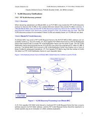
For example, a Public NL_Port in Figure 9.3 may be a Network File System (NFS) server that communicates<br />
with NFS Clients accessible via the fabric using Internet Protocol (IP), and with SCSI Targets<br />
on the same loop using the SCSI-3 FCP protocol.<br />
10
TR-xx-1998 Fibre Channel Tape Rev 1.07 August 7, 1998<br />
5 FC-2 feature sets<br />
The tables in this clause list features described in FC-PH, FC-PH-2, and FC-PH-3. These tables indicate<br />
whether the feature is Required, Prohibited, Allowable, or Invokable for compliance with this<br />
specification. Features that are not listed do not affect interoperability of Private NL_Ports.<br />
Reserved FC-PH, FC-PH-2, and FC-PH-3 fields are processed in accordance with the applicable<br />
standard or standards. Validity bits set to zero remove any requirement to check the corresponding<br />
field for zeroes and make the associated field meaningless (e.g., if F_CTL bit 3=0 in an FCP_DATA<br />
Sequence at a receiving NL_Port, the Relative Offset in the parameter field of the Frame header shall<br />
not be used in any way when reassembling the Sequence at the recipient).<br />
5.1 Node and port naming<br />
All SCSI Targets and Initiators complying with this profile shall have a unique Node_Name (WWN).<br />
Each FC-TAPE compliant NL_Port associated with these nodes shall also have a unique Port_Name<br />
(WWN). To ensure uniqueness of these names, all names shall use one of the registered name formats<br />
such as the IEEE or IEEE extended formats defined by FC-PH-3.<br />
All NL_Ports must acquire a valid AL_PA and Native Address Identifier before performing PLOGI with<br />
other NL_Ports.<br />
NL_Ports must retain the Node_Name and Port_Name of the other port from each PLOGI and associate<br />
that information with the Native Address Identifier of that NL_Port. This information shall be retained<br />
for as long as the PLOGI with the other port is active.<br />
SCSI Targets and SCSI Initiators shall validate current NL_Port logins following every Loop Initialization<br />
by comparing the Port Name, Node Name, and N_Port ID received during the PLOGI with those<br />
reported by the PDISC or ADISC that follows the Loop Initialization. All three identifiers reported during<br />
the PDISC or ADISC shall match the values reported during PLOGI or a configuration change has<br />
occurred and LOGO is required and all open Exchanges with that SCSI Initiator or SCSI Target will<br />
be terminated.<br />
Consider two examples os a DISC or ADISC request arriving at a SCSI Target, or ACC arriving at a<br />
SCSI Initiator in response to a PDISC or ADISC.<br />
Table 3 – PDISC, ADISC, ACC Examples<br />
Example Identifier PLOGI Data ADISC, PDISC, or ACC<br />
Data<br />
1<br />
2<br />
N_Port ID (24 bits) 00 00 AA 00 00 AB<br />
Node Name (64 bits) 1000 ABCD EF12 3456 1000 ABCD EF12 3456<br />
Port Name (64 bits) 1000 ABCD EF12 3457 1000 ABCD EF12 3457<br />
N_Port ID (24 bits) 0000AA 0000AA<br />
Node Name (64 bits) 1000 ABCD EF12 3456 1000 ABCD EF12 3456<br />
Port Name (64 bits) 1000 ABCD EF12 3456 1000 ABCD EF98 7654<br />
Response<br />
LOGO<br />
LOGO<br />
Example 1 may occur if a node with no Hard Address has been removed and reinserted into a reconfigured<br />
loop, and takes a different soft address.<br />
11
FC-Tape Fibre Channel Tape Rev 1.07 August 7, 1998<br />
Example 2 could occur if both ports of a node are connected to the same loop with the second port<br />
non-participating. The first port failed and was bypassed, and the second port assumed the AL_PA of<br />
the (now bypassed) first port.<br />
These examples, and other situations, such as loop reconfigurations or the connection of two formerly<br />
independent loops into a single loop, could result in one or more of the identifiers changing.<br />
12
5.2 FLOGI and PLOGI features and parameters for NL_Ports<br />
TR-xx-1998 Fibre Channel Tape Rev 1.07 August 7, 1998<br />
Table 4 lists features and parameters for FLOGI and PLOGI with usage defined by this document.<br />
Table 4 – FLOGI and PLOGI features and parameters for NL_Ports<br />
Feature/Parameter<br />
NL_Port NL_Port Notes<br />
Originator Responder<br />
FLOGI S_ID hex’0000’||AL_PA -<br />
Class of service for FLOGI 1<br />
Class 2 I A<br />
Class 3 I A<br />
Class of service for PLOGI 1<br />
Class 2 I A<br />
Class 3 I A<br />
Supported Classes of Service 1<br />
Class 1 P P<br />
Class 2 I A<br />
Class 3 I A<br />
Class 4 and up P P<br />
NOTES:<br />
1 Implementations conforming to this profile may support Class 2 and/or Class 3.<br />
13
FC-Tape Fibre Channel Tape Rev 1.07 August 7, 1998<br />
5.3 NL_Port and N_Port Common Service Parameters (PLOGI)<br />
Table 5 lists NL_Port and N_Port Common Service Parameters for PLOGI with usage defined by this<br />
document. The parameters are valid for both Class 2 and Class 3 delivery service.<br />
Table 5 – NL_Port and N_Port Common Service Parameters (PLOGI)<br />
Common Service Parameter<br />
SCSI SCSI Notes<br />
Initiator Target<br />
FC-PH Version<br />
Highest Version X X 1<br />
Lowest Version hex’20’ hex’20’<br />
Buffer-to-Buffer Credit (min) 0 0 4<br />
Common Features<br />
Continuously Increasing Relative Offset 1 1<br />
Random Relative Offset 0 0<br />
Valid Vendor Version Level 0 0 2<br />
N_Port/F_Port 0 0<br />
Alternate BB_Credit Management 1 1 4<br />
E_D_TOV Resolution 0 0 4<br />
Dynamic Half Duplex - DHD A A<br />
SEQ_CNT A A<br />
Payload Length 0 0<br />
Buffer-to-Buffer Receive Data Field Size (min) 256 256 4<br />
Total Concurrent Sequences (min) 1 1<br />
Relative Offset by Information Category<br />
Information Category 1 (Solicited Data) R R<br />
Information Category 5 (Data Descriptor) R R<br />
All other Information Categories A A 3<br />
R_A_TOV - -<br />
E_D_TOV see 7.4 see 7.4 4<br />
NOTES:<br />
1 The FC-PH version shall include a version of FC-PH-2 or FC-PH-3 that includes PDISC, ADISC, TPR-<br />
LO, and RNC (previously known as RVU). PDISC, ADISC, and TPRLO are described in FC-PH-2, RNC<br />
is described in FC-PH-3. Hex‘20’ is the version assigned to FC-PH-3.<br />
2 Profile versions are communicated via the Report Node Capabilities (RNC) ELS. The Valid Vendor Version<br />
Level shall not be set to 1 for communicating support of this Technical Report.<br />
3 Relative offset is not required for any other Information Categories. The Sequence Initiator is allowed to<br />
set the bit but the Sequence Recipient may ignore it.<br />
4 Field does not apply to a direct Fabric-attached device.<br />
14
5.4 NL_Port Common Service Parameters (FLOGI)<br />
TR-xx-1998 Fibre Channel Tape Rev 1.07 August 7, 1998<br />
Table 5 lists NL_Port Common Service Parameters for FLOGI with usage defined by this document.<br />
The parameters are valid for both Class 2 and Class 3 delivery service.<br />
Table 6 – NL_Port and N_Port Common Service Parameters (FLOGI)<br />
Common Service Parameter<br />
NL_Port Notes<br />
Originator<br />
FC-PH<br />
Highest Version X 1<br />
Lowest Version<br />
hex’20’<br />
Buffer-to-Buffer Credit (min) 0<br />
Common Features<br />
Continuously Increasing Relative Offset -<br />
Random Relative Offset -<br />
Valid Vendor Version Level 0 2<br />
N_Port/F_Port 0<br />
Alternate BB_Credit Management 1<br />
E_D_TOV Resolution -<br />
Dynamic Half Duplex - DHD<br />
A<br />
SEQ_CNT -<br />
Payload Length 0<br />
Buffer-to-Buffer Receive Data Field Size (min) 256<br />
Total Concurrent Sequences (min) -<br />
Relative Offset by Information Category -<br />
R_A_TOV -<br />
E_D_TOV -<br />
NOTES:<br />
1 The FC-PH version shall include a version of FC-PH-2 or FC-PH-3 that includes PDISC, ADISC,<br />
TPRLO, and RNC (previously known as RVU). PDISC, ADISC, and TPRLO are described in FC-<br />
PH-2, RNC is described in FC-PH-3. Hex‘20’ is the version assigned to FC-PH-3.<br />
2 Profile versions are communicated via the Report Node Capabilities (RNC) ELS. The Valid Vendor<br />
Version Level shall not be set to 1 for communicating support of this Technical Report.<br />
15
FC-Tape Fibre Channel Tape Rev 1.07 August 7, 1998<br />
5.5 NL_Port and N_Port Class 2 Service Parameters (PLOGI)<br />
Table 7 lists Class 2 Service Parameters for PLOGI with usage defined by this document.<br />
Table 7 – Class 2 Service Parameters (PLOGI)<br />
Class 2 Service Parameter<br />
SCSI SCSI Notes<br />
Initiator Target<br />
Class validity 1 1<br />
Service Options<br />
Intermix Mode - -<br />
Stacked Connect Requests - -<br />
Sequential Delivery - -<br />
Dedicated Simplex - -<br />
Camp-On - -<br />
Buffered Class 1 - -<br />
Priority 0 0<br />
Initiator Control<br />
X_ID reassignment ‘00’b ‘00’b<br />
Initial Responder Process_Associator ‘00’b ‘00’b<br />
ACK_0 capable A A<br />
ACK_N capable 0 0<br />
ACK generation assistance A A<br />
Data compression capable 0 0<br />
Data compression History buffer size - -<br />
Data encryption capable 0 0<br />
Clock synchronization capable A A<br />
Recipient Control<br />
ACK_0 capable A A<br />
ACK_N capable 0 0<br />
X_ID interlock R A 1<br />
Error Policy Supported<br />
Abort, discard multiple Sequences (‘00’b) A A<br />
Abort, discard a single Sequence (’01’b) R R<br />
Process policy with infinite buffers (‘10’b) P P<br />
Discard multiple sequences w/immediate retrans (‘11’b) P P<br />
Categories per Sequence ‘00’b ‘00’b<br />
Data compression capable 0 0<br />
Data compression History buffer size - -<br />
Data decryption capable 0 0<br />
Clock synchronization capable A A<br />
Reserved - Fabric specific 0 0<br />
Receive data field size (min) 256 256<br />
Concurrent Sequences (min) 1 1<br />
N_Port End-to-end Credit (min) 1 1<br />
Open Sequences per Exchange (min) 1 1<br />
NOTES:<br />
1 The Sequence Initiator shall provide X_ID Interlock if required by the Sequence Recipient. If an RX_ID<br />
other than hex ‘FFFF” is used by an Exchange Responder, it shall return the RX_ID value in the first Sequence<br />
transmitted as a Sequence Initiator.<br />
16
5.6 NL_Port Class 2 Service Parameters (FLOGI)<br />
TR-xx-1998 Fibre Channel Tape Rev 1.07 August 7, 1998<br />
Table 8 lists Class 2 Service Parameters for FLOGI with usage defined by this document.<br />
Table 8 – Class 2 Service Parameters (FLOGI)<br />
Class 2 Service Parameter<br />
SCSI<br />
Initiator<br />
SCSI<br />
Target<br />
Class validity 1 1<br />
Service Options<br />
Intermix Mode - -<br />
Stacked Connect Requests - -<br />
Sequential Delivery 1 1<br />
Dedicated Simplex - -<br />
Camp-On - -<br />
Buffered Class 1 - -<br />
Priority 0 0<br />
Initiator Control<br />
X_ID reassignment - -<br />
Initial Responder Process_Associator - -<br />
ACK_0 capable - -<br />
ACK_N capable - -<br />
ACK generation assistance - -<br />
Data compression capable - -<br />
Data compression History buffer size - -<br />
Data encryption capable - -<br />
Clock synchronization capable A A<br />
Recipient Control<br />
ACK_0 capable - -<br />
ACK_N capable - -<br />
X_ID interlock - -<br />
Error Policy Supported<br />
Abort, discard multiple Sequences (‘00’b) - -<br />
Abort, discard a single Sequence (’01’b) - -<br />
Process policy with infinite buffers (‘10’b) - -<br />
Discard multiple sequences w/immediate retrans (‘11’b) - -<br />
Categories per Sequence - -<br />
Data compression capable - -<br />
Data compression History buffer size - -<br />
Data decryption capable - -<br />
Clock synchronization capable A A<br />
Reserved - Fabric specific 0 0<br />
Receive data field size (min) - -<br />
Concurrent Sequences (min) - -<br />
N_Port End-to-end Credit (min) - -<br />
Open Sequences per Exchange (min) - -<br />
NOTES:<br />
Notes<br />
17
FC-Tape Fibre Channel Tape Rev 1.07 August 7, 1998<br />
5.7 NL_Port and N_Port Class 3 Service Parameters (PLOGI)<br />
Table 9 lists Class 3 Service Parameters for PLOGI with usage defined by this document.<br />
Table 9 – Class 3 Service Parameters (PLOGI)<br />
Class 3 Service Parameter<br />
SCSI<br />
Initiator<br />
SCSI<br />
Target<br />
Class validity 1 1<br />
Service Options<br />
Intermix Mode - -<br />
Stacked Connect Requests - -<br />
Sequential Delivery - -<br />
Dedicated Simplex - -<br />
Camp-On - -<br />
Buffered Class 1 - -<br />
Priority - -<br />
Initiator Control<br />
X_ID reassignment - -<br />
Initial Responder Process_Associator ‘00’b ‘00’b<br />
ACK_0 capable - -<br />
ACK_N capable - -<br />
ACK generation assistance - -<br />
Data compression capable 0 0<br />
Data compression History buffer size - -<br />
Data encryption capable 0 0<br />
Clock synchronization capable A A<br />
Recipient Control<br />
ACK_0 capable - -<br />
ACK_N capable - -<br />
X_ID interlock - -<br />
Error Policy Supported<br />
Abort, discard multiple Sequences (‘00’b) A A<br />
Abort, discard a single Sequence (’01’b) R R<br />
Process policy with infinite buffers (‘10’b) P P<br />
Discard multiple sequences w/immediate retrans (‘11’b) P P<br />
Categories per Sequence ‘00’b ‘00’b<br />
Data compression capable 0 0<br />
Data compression History buffer size - -<br />
Data decryption capable 0 0<br />
Clock synchronization capable A A<br />
Reserved - Fabric specific 0 0<br />
Receive data field size (min) 256 256<br />
Concurrent Sequences (min) 1 1<br />
N_Port End-to-end Credit - -<br />
Open Sequences per Exchange (min) 1 1<br />
Notes<br />
18
5.8 NL_Port Class 3 Service Parameters (FLOGI)<br />
TR-xx-1998 Fibre Channel Tape Rev 1.07 August 7, 1998<br />
Table 9 lists Class 3 Service Parameters for FLOGI with usage defined by this document.<br />
Table 10 – Class 3 Service Parameters (FLOGI)<br />
Class 3 Service Parameter<br />
SCSI<br />
Initiator<br />
SCSI<br />
Target<br />
Class validity 1 1<br />
Service Options<br />
Intermix Mode - -<br />
Stacked Connect Requests - -<br />
Sequential Delivery 1 1<br />
Dedicated Simplex - -<br />
Camp-On - -<br />
Buffered Class 1 - -<br />
Priority 0 0<br />
Initiator Control<br />
X_ID reassignment - -<br />
Initial Responder Process_Associator - -<br />
ACK_0 capable - -<br />
ACK_N capable - -<br />
ACK generation assistance - -<br />
Data compression capable - -<br />
Data compression History buffer size - -<br />
Data encryption capable - -<br />
Clock synchronization capable A A<br />
Recipient Control<br />
ACK_0 capable - -<br />
ACK_N capable - -<br />
X_ID interlock - -<br />
Error Policy Supported<br />
Abort, discard multiple Sequences (‘00’b) - -<br />
Abort, discard a single Sequence (’01’b) - -<br />
Process policy with infinite buffers (‘10’b) - -<br />
Discard multiple sequences w/immediate retrans (‘11’b) - -<br />
Categories per Sequence - -<br />
Data compression capable - -<br />
Data compression History buffer size - -<br />
Data decryption capable - -<br />
Clock synchronization capable A A<br />
Reserved - Fabric specific 0 0<br />
Receive data field size (min) - -<br />
Concurrent Sequences (min) - -<br />
N_Port End-to-end Credit - -<br />
Open Sequences per Exchange (min) - -<br />
Notes<br />
19
FC-Tape Fibre Channel Tape Rev 1.07 August 7, 1998<br />
5.9 Other FC-2 features<br />
Table 11 lists other FC-2 features with usage defined by this document.<br />
Table 11 – Other FC-2 Features<br />
Feature<br />
SCSI SCSI Notes<br />
Initiator Target<br />
R_CTL Routing Bits<br />
FC-4 Device_Data Frame (‘0000’b) R R<br />
Extended Link_Data Frame (‘0010’b) R R<br />
FC-4 Link_Data Frame (‘0011’b) P P<br />
Video_Data Frame (‘0100’b) P P<br />
Basic Link_Data Frame (‘1000’b) R R<br />
Link_Control Frame (‘1100’b)<br />
Class 2 delivery service R R 1<br />
Class 3 delivery service P P 1<br />
Continue Sequence Condition = ‘00’b R R<br />
Ignore nonzero Continue Sequence values A A<br />
Sequence Chaining (C_S bit in F_CTL) = 0 R R<br />
Optional Headers (all) P P<br />
Node Name Format<br />
Uses a Registered Format R R 2<br />
Uses a non-Registered Format P P<br />
Port Name Format<br />
Uses a Registered Format R R 2<br />
Uses a non-Registered Format P P<br />
Node_Name = N_Port Name P P 3<br />
Continuously increasing Sequence count during consecutive<br />
Sequences within an Exchange<br />
NOTES:<br />
A<br />
A<br />
4 and<br />
see<br />
5.13.3<br />
1 Link Control Frames are required for Class 2. A SCSI Initiator or Target that supports only Class 3 shall<br />
return a P_RJT using Class 2 if a Link Control Frame is received.<br />
2 Node Names and N_Port Names shall use a format that contains a worldwide unique identifier issued<br />
by a recognized registration authority. The IEEE and IEEE Extended name formats are two examples of<br />
acceptable formats.<br />
3 The use of unique identifiers for both the Node_Name and Port_Name is required.<br />
4 The use of a continuously increasing sequence count is strongly recommended to provide enhanced error<br />
detection.<br />
20
TR-xx-1998 Fibre Channel Tape Rev 1.07 August 7, 1998<br />
5.10 Basic Link Service commands<br />
Table 12 lists Basic Link Service commands with usage defined by this document. NL_Ports may implement<br />
Prohibited Basic Link Service commands although their usage may be Prohibited by this<br />
profile.<br />
Feature<br />
Table 12 – Basic Link Services<br />
Orig. By<br />
SCSI<br />
Initiator<br />
Resp. By<br />
SCSI<br />
Target<br />
Orig. By<br />
SCSI<br />
Target<br />
Resp. By<br />
SCSI<br />
Initiator<br />
No Operation (NOP) P - P -<br />
Abort Sequence (ABTS) I R I R<br />
Basic Accept (BA_ACC) R R R R<br />
Basic Reject (BA_RJT) R R R R<br />
Remove Connection (RMC) (Class 1 only) P - P -<br />
Dedicated Connection Preempted (PRMT) P - P -<br />
5.11 Extended Link Services<br />
Table 13 lists Extended Link Services with usage defined by this document.<br />
Devices that receive requests for Extended Link Services that are unsupported shall return LS_RJT<br />
with a reason code “Command not supported.”<br />
Table 13 – Extended Link Services<br />
Extended Link Service<br />
Orig. By<br />
SCSI<br />
Initiator<br />
Resp. By<br />
SCSI<br />
Target<br />
Orig. By<br />
SCSI<br />
Target<br />
Resp. By<br />
SCSI<br />
Initiator<br />
Note<br />
Accept (ACC) R R R R<br />
Discover Address (ADISC) I R P 1<br />
Discover N_Port Parameters (PDISC) I R P 1<br />
Fabric Login (FLOGI) I I 2,5,6<br />
Fabric Address Notification (FAN) I I 1,5<br />
Discover F_Port Parameters (FDISC) I I 5<br />
Loop Initialize (LINIT) I I 6<br />
Logout (LOGO) I R I R<br />
Loop Port Control (LPC) I I 6<br />
Link Service Reject (LS_RJT) R R R R<br />
Loop Status (LSTS) I I 6<br />
N_Port Login (PLOGI) R R P<br />
21
FC-Tape Fibre Channel Tape Rev 1.07 August 7, 1998<br />
Table 13 – Extended Link Services<br />
Extended Link Service<br />
Orig. By<br />
SCSI<br />
Resp. By<br />
SCSI<br />
Initiator Target Target<br />
Process Login (PRLI) R R P<br />
PRLI Common Service Parameters P P<br />
Single Service Parameter page per<br />
PRLI request<br />
R R P<br />
Multiple Service Parameter pages per<br />
PRLI request<br />
P<br />
P<br />
ACC contains only those pages<br />
specified in PRLI<br />
- R P<br />
Accept Response code=“Command<br />
executed”<br />
- R P<br />
Process Logout (PRLO) I R I R<br />
Read Exchange Concise (REC) R R P 4,7<br />
Read Link Error Status Block (RLS) I R P 3<br />
Report Node Capabilities Information<br />
(RNC)<br />
I R P<br />
Reinstate Recovery Qualifier (RRQ) I R P<br />
Request Sequence Initiative (RSI) A A A A 4<br />
Read Sequence Status Block (RSS) A A A A 4<br />
Sequence Retransmission Request<br />
(SRR)<br />
I R P 7<br />
Third Party Process Logout (TPRLO) I R P<br />
Any unlisted Extended Link Service P P<br />
NOTES:<br />
1 See 10.3 for a description of SCSI Target Discovery. Only ADISC or PDISC is required by a SCSI Initiator,<br />
but not both. SCSI Targets shall support receipt of both, for interoperability with SCSI Initiators that<br />
support one or the other. ADISC is the preferred method for Private NL_Ports.<br />
2 Private NL_Ports are prohibited from performing FLOGI. Public NL_Ports whose FLOGI fails (i.e. no<br />
FL_Port is present on the loop) may revert to Private behavior.<br />
3 Not all fields in the LESB may be supported (see vendor-specific documentation). RLS can be a diagnostic<br />
tool for isolating link degradation. Using RLS, diagnostic software can use a combination of<br />
self-directed test Frames, LPB, and LESB polling to determine which device or link segment is causing<br />
link errors.<br />
4 These link services permit the progress in a Sequence or Exchange at the Sequence Responder to be<br />
made visible for recovery purposes by a Sequence Initiator (e.g., determine whether a Sequence was<br />
delivered before using ABTS).<br />
5 Required for Public Loop NL_Ports only.<br />
6 FAN is the preferred method for Public NL_Ports to authenticate addresses following loop initialization.<br />
7 Refer to clause 9 and Annex A.<br />
Orig. By<br />
SCSI<br />
Resp. By<br />
SCSI<br />
Initiator<br />
Note<br />
22
TR-xx-1998 Fibre Channel Tape Rev 1.07 August 7, 1998<br />
5.12 Responses to Link Services<br />
Table 14 summarizes the responses that shall be generated as a result of receiving selected Link<br />
Service requests.<br />
Table 14 – Responses to Selected Link Services<br />
Frame Received PLOGI Not Successfully Completed PLOGI Successfully Completed<br />
ABTS Discard and send LOGO BA_ACC, BA_RJT (note 2)<br />
ADISC Discard and send LOGO ACC (note 1), LS_RJT<br />
LOGO ACC ACC<br />
PDISC Discard and send LOGO ACC (note 1), LS_RJT<br />
PLOGI ACC, LS_RJT (notes 4,5) ACC<br />
PRLI Discard and send LOGO ACC<br />
PRLO Discard and send LOGO ACC, LS_RJT (note 3)<br />
Unlisted Link<br />
ACC, LS_RJT (as appropriate and<br />
Discard and send LOGO<br />
Service<br />
defined by the applicable standard)<br />
NOTES:<br />
1 All three identifiers: N_Port ID, Port Name, and Node Name shall match a logged-in NL_Port for ACC to<br />
be returned. If all three identifiers do not match LOGO is returned. If other conditions prevent execution<br />
of the ADISC or PDISC ELS, LS_RJT may be returned as defined by the applicable standard with the<br />
appropriate reason code.<br />
2 BA_ACC or BA_RJT as specified in clause 9.5<br />
3 If PRLI has not been successfully completed, set the reason code to “image pair does not exist”.<br />
4 An NL_Port that does not wish to accept a PLOGI may return LS_RJT with a reason code of “Command<br />
Not Supported”. This could occur if a SCSI Initiator receives a PLOGI and does not wish to support SCSI<br />
Initiator to SCSI Initiator communication.<br />
5 An NL_Port that is not ready to accept a PLOGI at this time may return LS_RJT with a reason code of<br />
“Logical Busy”.<br />
While not shown in the table, an NL_Port shall return LS_RJT to any Extended Link Service request<br />
if that request is not properly formed or supported by the recipient NL_Port.<br />
An NL_Port that has discarded a Frame as shown in Table 14 shall not create an Exchange for the<br />
discarded request. Upon receipt of the LOGO, the originator of the discarded Frame terminates the<br />
Exchange associated with the discarded Frame and any other open Exchanges for the NL_Port<br />
sending the LOGO. The LOGO Sequence is in a separate Exchange with the original recipient as the<br />
Exchange Originator.<br />
5.13 Exchange and Sequence management<br />
This subclause describes required and optional behavior required of devices conforming to this profile.<br />
Refer to the FC-PH document(s) for rules and guidelines pertaining to class 2 operation.<br />
23
FC-Tape Fibre Channel Tape Rev 1.07 August 7, 1998<br />
5.13.1 Exchange Originator<br />
The Originator of each FCP Exchange shall assign an OX_ID value other than hex ’FFFF’ to that Exchange.<br />
The Exchange Originator shall maintain OX_ID uniqueness with a given Responder.<br />
Exchange Originators are not assured of RX_ID uniqueness across multiple Responders, nor that a<br />
Responder will assign an RX_ID other than hex ’FFFF’. The Exchange Originator shall qualify the<br />
RX_ID with the Native Address Identifier of the Responder, if used by the Responder.<br />
Since the environment defined by this document ensures in-order delivery of Frames and requires<br />
that Frames are processed in the order received, a set of simplifying assumptions can be made regarding<br />
when an Exchange is open.<br />
The Exchange Originator shall consider the Exchange open from the time the first Frame of the first<br />
information unit (Frame with the First_Sequence bit in the F_CTL field set to 1) is sent until one of the<br />
following occurs:<br />
• the last Frame of the last information unit (Frame with the Last_Sequence bit in the F_CTL field<br />
set to 1) is sent or received;<br />
• the Exchange is aborted using ABTS (see 9.5) and a response to the ABTS is received;<br />
• a LOGO is sent to, or received from, the Exchange Responder;<br />
• an LS_RJT is sent in response to an ADISC or PDISC during Target discovery.<br />
• a PLOGI is sent to the Exchange Responder<br />
5.13.2 Exchange Responder<br />
Exchange Responders may optionally assign an RX_ID or use the value of hex ’FFFF’.<br />
Exchange Responders in a multiple Originator environment are not assured of OX_ID uniqueness<br />
across multiple Originators and shall qualify the OX_ID with the Native Address Identifier of the Originator.<br />
Exchange Responders are not required to check for OX_ID uniqueness with a given Originator.<br />
The Exchange Responder shall consider the Exchange open from the time the first Frame of the first<br />
information unit (Frame with the First_Sequence bit in the F_CTL field set to 1) is received until one<br />
of the following occurs:<br />
• the last Frame of the last information unit (Frame with the Last_Sequence bit in the F_CTL field<br />
set to 1) is sent or a FCP_CONF is received;<br />
• the Exchange is aborted using ABTS (see 9.5) and a response to the ABTS is sent;<br />
• a LOGO is sent to, or received from, the Exchange Originator;<br />
• an LS_RJT is sent in response to an ADISC or PDISC during Target discovery.<br />
• a PLOGI is received<br />
24
TR-xx-1998 Fibre Channel Tape Rev 1.07 August 7, 1998<br />
5.13.3 Sequence management<br />
The following subclauses define Sequence management requirements for devices operating in accordance<br />
with this document.<br />
5.13.3.1 Sequence open<br />
The Sequence Initiator shall consider a Sequence open from the time that the first Frame of the Sequence<br />
(the Frame with the SOFi3 delimiter) is sent until one of the following occurs:<br />
• the last Frame of the Sequence (the Frame with the EOFt delimiter) is sent and<br />
R_A_TOV SEQ_QUAL has elapsed;<br />
• the Sequence is aborted using ABTS and a response to the ABTS is sent or received, as appropriate;<br />
• a LOGO is sent to, or received from, the Sequence recipient.<br />
The Sequence Recipient shall consider a Sequence open from the time that the first Frame of the Sequence<br />
(the Frame with the SOFi3 delimiter) is received until one of the following occurs:<br />
• the last Frame of the Sequence (the Frame with the EOFt delimiter) is received;<br />
• the Sequence is aborted using ABTS and a response to the ABTS is sent or received, as appropriate;<br />
• a LOGO is sent to, or received from, the Sequence Initiator.<br />
5.13.3.2 SEQ_ID and SEQ_CNT usage<br />
The following paragraphs summarize the rules governing reuse of SEQ_IDs and SEQ_CNT as applicable<br />
to devices conforming to this profile.<br />
For all Sequences,<br />
a) Consecutive Sequences to the same destination within the same Sequence initiative shall use<br />
different SEQ_IDs.<br />
For Sequences that transfer Sequence Initiative,<br />
a) An NL_Port may reuse a SEQ_ID following confirmation of Sequence delivery (see 8.6 for a list<br />
of FCP Sequences whose delivery can be determined);<br />
b) An NL_Port may reuse the SEQ_ID of the last Sequence of an Exchange immediately following<br />
transmission of the last Frame of that Sequence (the Sequence Initiator may consider the Sequence<br />
delivered upon completion of transmission).<br />
For Sequences that do not transfer Sequence Initiative,<br />
a) Consecutive FCP_DATA Sequences for the same Exchange shall follow the FC-PH, FC-PH-2,<br />
and FC-PH-3 rules for streamed Sequences (an example of this occurs when multiple<br />
FCP_DATA Sequences are used during a single read operation). The rules for streamed Sequences<br />
are summarized in the following list (refer to FC-PH, FC-PH-2, and FC-PH-3 for complete<br />
streamed Sequence requirements):<br />
25
FC-Tape Fibre Channel Tape Rev 1.07 August 7, 1998<br />
1) The first FCP_DATA Sequence after transfer of Sequence Initiative is not a streamed Sequence.<br />
It may use any eligible SEQ_ID and the SEQ_CNT may be either zero or continuously<br />
increasing (incremented by one from the last Frame of the previous Sequence of that<br />
Exchange);<br />
NOTE – Some existing devices require the SEQ_CNT for the first FCP_DATA Frame following the transfer<br />
of Sequence Initiative to be zero.<br />
2) The second, and subsequent, Sequences of a group of consecutive Sequences within the<br />
same Exchange shall be treated as streamed. The following rules apply (where X in the following<br />
discussion is the number of Open Sequences per Exchange from PLOGI (see table<br />
9)):<br />
NOTES:<br />
i) X+1 different SEQ_IDs shall be used;<br />
ii) The X+1 different SEQ_IDs may be assigned by the Sequence Initiator in any order (they<br />
are not required to be monotonically increasing);<br />
iii) A SEQ_ID may be reused after X different intervening SEQ_IDs have been used, provided<br />
that R_A_TOV SEQ_QUAL (as defined in 7.5) has expired for all Frames associated with the<br />
prior use of that SEQ_ID;<br />
iv) The Sequence Count (SEQ_CNT) across streamed Sequences shall be continuously increasing.<br />
That is, the SEQ_CNT of the first Frame of the streamed Sequence shall be incremented<br />
by one from the SEQ_CNT of the last Frame of the previous Sequence;<br />
1 FC-PH-3 adds a bit to PLOGI that indicates that a port uses continuously increasing SEQ_CNT on all Sequences<br />
within an Exchange with the first Sequence of the Exchange beginning at SEQ_CNT zero. Ports<br />
that set this bit during login are obligated to follow this behavior since the Sequence Recipient may use the<br />
expected behavior to perform Sequence checking.<br />
2 Some existing devices are not capable of generating continuously increasing SEQ_CNT across consecutive<br />
Sequences. In this case, the following rules apply: A minimum of two different SEQ_IDs shall be used<br />
by the Sequence Initiator and the SEQ_CNT across consecutive Sequences may restart at x‘0000’.<br />
b) The Target may use one or more Sequences to transfer the data requested by a SCSI readtype<br />
command. The Target may break the associated transfer up into as many arbitrary sized<br />
Sequences as the Target chooses (subject to the Sequence boundary requirements specified<br />
elsewhere in this document). This means that:<br />
1) When there is additional read data still to transfer and all of the data Frames associated with<br />
a given Sequence have been sent, or all permissible SEQ_CNT values used, the Target may<br />
begin a new Sequence in order to continue sending the read data;<br />
2) The Target may send less than the maximum permissable number of data Frames per<br />
FCP_DATA Sequence, even if there is additional data to send (for example, if the maximum<br />
Sequence size is 1000 Frames (as defined by the maximum burst size field of the SCSI disconnect/reconnect<br />
mode page), the Target may terminate the current Sequence after 600<br />
Frames and subsequently start a new Sequence to send any remaining Frames).<br />
c) During a read type command with at least one FCP_DATA Sequence, the FCP_RSP Sequence<br />
may optionally be considered a streamed Sequence and observe the rules for<br />
streamed Sequences listed previously.<br />
26
TR-xx-1998 Fibre Channel Tape Rev 1.07 August 7, 1998<br />
d) A SCSI Target may reuse a SEQ_ID previously used for a Read FCP_DATA Sequence immediately<br />
following transmission of the FCP_RSP of that Exchange.<br />
Examples of SEQ_ID and SEQ_CNT usage during streamed Sequences may be found in Annex B.<br />
5.13.4 Sequence errors<br />
The following conditions shall constitute a Sequence error when detected by the Sequence Recipient:<br />
a) if a Frame with an SOFi3 delimiter is received and the SEQ_CNT is not equal to zero or +1<br />
from the SEQ_CNT of the last Frame of the previous Sequence of that Exchange;<br />
b) if the SEQ_CNT of a received Frame with an SOFn3 delimiter is not +1 greater than the previous<br />
Frame received for that Sequence (i.e., a Frame was lost);<br />
c) if a Frame with an SOFn3 delimiter is received for a SEQ_ID that is not currently open;<br />
d) if a Frame with an SOFi3 delimiter is received and the previous Sequence of that Exchange is<br />
still open (see 5.13.3.1 for a definition of when a Sequence is open);<br />
e) if the relative offset bit in the F_CTL field is set to ‘1’b and the value contained in the parameter<br />
field of a received Frame with an SOFn3 delimiter is not equal to the (relative offset + the payload<br />
size) of the previous Frame received for that Sequence;<br />
f) the next Frame of a Sequence is not received within E_D_TOV;<br />
g) if, during the same Sequence Initiative, a Sequence is received that has the same SEQ_ID as<br />
the immediately prior Sequence of that Exchange.<br />
Refer to the FC-PH document(s) for a description of Sequence errors pertaining to class 2 operation.<br />
When a Sequence error is detected by the Sequence Recipient, it shall take the appropriate action as<br />
described in clause 9.<br />
27
FC-Tape Fibre Channel Tape Rev 1.07 August 7, 1998<br />
6 FC-AL feature set<br />
This clause describes the use of Fibre Channel Arbitrated Loop features and capabilities by devices<br />
that conform to this document. Devices shall be compliant with FC-AL-2.<br />
6.1 FC-AL features<br />
Table 15 lists Fibre Channel Arbitrated Loop features with usage defined by this document.<br />
Table 15 – FC-AL Features<br />
Feature<br />
SCSI<br />
Initiator<br />
SCSI<br />
Target<br />
Open Full Duplex - OPN(yx)<br />
Open Originator can send I I<br />
Open Recipient accepts R R<br />
Open Half Duplex - OPN(yy)<br />
Open Originator can send I I<br />
Open Recipient accepts R R<br />
Open Multicast/Selective Replicate - OPN(yr), OPN(fr)<br />
Open Originator can send P P<br />
Login_BB_Credit<br />
Advertise Login_BB_Credit >= 0 A A<br />
Accept Login_BB_Credit >= 0 R R 3<br />
LPEyx/LPByx/LPEfx<br />
Origination P P 1<br />
MRKtx origination P P 4<br />
Attempt to acquire Hard Address (by devices having a Hard Address<br />
defined) during LIHA Sequence of loop initialization following a R R 5<br />
power cycle, power-on reset, or recognition of LIP(AL_PD,AL_PS)<br />
LILP/LIRP<br />
Loop Master shall originate R R 2<br />
Non-loop Master L_Ports accept R R 2<br />
NOTES:<br />
Notes<br />
1 LPEfx is useful for resetting the bypass circuits of NL_Ports that have been bypassed and have lost<br />
their AL_PAs due to an intervening LIP (and therefore cannot be enabled using an addressed LPEyx).<br />
SCSI Targets complying with SFF-8045 shall be able to recognize LPE/LPB directed to the appropriate<br />
AL_PA and toggle the corresponding port bypass enable signal.<br />
2 The initialization Loop Master shall originate the LIRP/LILP Sequences if the Loop Initialization identifier<br />
(in the LISA Frame) is hex ‘11050100’. Any L_Port (including the Loop Master) that is not capable of<br />
supporting LIRP/LILP shall set the Loop Initialization identifier (in the LISA Frame) to hex‘11050000’ to<br />
indicate that the LIRP/LILP Sequences shall not be originated.<br />
3 The actual value used shall be between zero and the Login_BB_Credit value received during PLOGI.<br />
4 An NL_Port that receives a MRK shall attempt to forward the MRK per FC-AL rules. FC-AL states that<br />
an L_Port may remove a MRK if necessary for clock skew management.<br />
5 Ports complying with SFF-8045 shall attempt to acquire the Hard Address presented by the SFF-8045<br />
defined interface.<br />
28
6.2 Alternate Login_BB_Credit management<br />
TR-xx-1998 Fibre Channel Tape Rev 1.07 August 7, 1998<br />
OPN Originators may open full or half duplex, regardless of the value of Login_BB_Credit. See Annex<br />
A for examples.<br />
Interoperability with devices that advertise Login_BB_Credit=0 is required.<br />
After completing the Loop Initialization Procedure, Login_BB_Credit shall be zero with all devices until<br />
after completion of the SCSI Target Discovery protocol (see 10.3).<br />
NOTE – This is essential for two reasons: The device at a particular address that had Login_BB_Credit > 0<br />
may have been replaced by a device with Login_BB_Credit = 0. Until SCSI Target Discovery is complete,<br />
there is no way to be sure that the port is communicating with the Login_BB_Credit > 0 device. Secondly, a<br />
device may have been trying to balance credit by not sending CLS when the LIP occurred. The LIP could have<br />
prematurely forced the device into the MONITORING state at a time when it has insufficient buffers available.<br />
Requiring SCSI Target Discovery before assuming Login BB_Credit > 0 enables the device to free its buffers<br />
before attempting to resume normal operations.<br />
6.3 Loop Initialization features<br />
NOTE – The information in this subclause is provided for information only and is not intended as a replacement<br />
for the relevant standard.<br />
NL_Ports shall attempt to acquire their previously acquired AL_PA before they attempt to acquire<br />
their Hard Address, unless the NL_Port has experienced a power cycle, power-on reset, recognized<br />
a LIP(AL_PD,AL_PS) for that port, or any other event that causes the previously acquired AL_PA to<br />
be lost.<br />
6.3.1 Initializing LIP(F7,F7) and LIP(F7,AL_PS)<br />
If there are no address conflicts, these LIPs shall have no effect on existing Exchanges except that<br />
the Exchange in progress may be disrupted, resulting in a ULP timeout. LIP(F7,F7) is used if the initiating<br />
NL_Port has no valid AL_PA, and LIP(F7,AL_PS) is used if it does.<br />
6.3.2 Selective Hard Reset LIP(AL_PD,AL_PS)<br />
Upon recognition of LIP(AL_PD,AL_PS) the NL_Port designated by AL_PD shall perform the appropriate<br />
resetting actions specified in table 23. All other L_Ports shall treat this as LIP(F7,AL_PS). SCSI<br />
Targets are prohibited from issuing this LIP.<br />
6.3.3 Loop Failure LIP(F8,AL_PS) and LIP(F8,F7)<br />
A Loop Failure is defined as detection of any of the following:<br />
a) Loss of Signal<br />
b) Loss of Synchronization for longer than R_T_TOV<br />
If a Loop Failure occurs, the L_Port which detects the failure shall issue LIP(F8,AL_PS) if it has a valid<br />
AL_PA, or LIP(F8,F7) if it doesn’t.<br />
6.3.4 Failure to obtain an AL_PA<br />
An L_Port which loses its previously acquired address shall implicitly logout all NL_Ports regardless<br />
of whether or not that AL_PA was previously-assigned, hard-assigned, or soft-assigned. If no soft ad-<br />
29
FC-Tape Fibre Channel Tape Rev 1.07 August 7, 1998<br />
dress is available, it shall go to non-participating mode. An NL_Port which has experienced a power<br />
cycle, received a power-on reset, or recognized a LIP(AL_PD,AL_PS) is not required to retain a previously<br />
acquired address to use during the next loop initialization.<br />
30
7 Timers on Public and Private Loop<br />
TR-xx-1998 Fibre Channel Tape Rev 1.07 August 7, 1998<br />
FC-PH requirements for timers are summarized in Annex A. This clause defines the timers and timeout<br />
values used for Public and Private Loop implementations.<br />
Table 16 – Timer Summary<br />
Timer Implemented by Description Value<br />
Initiator Target<br />
AL_TIME R R Arbitrated Loop Timeout Value 15 ms per FC-AL<br />
LIS_HOLD_TIME R R Loop Initialization Sequence Hold<br />
1 ms<br />
Time<br />
R_T_TOV R R Receiver_Transmitter Timeout 100 ms per FC-PH<br />
Value<br />
E_D_TOV R A Error_Detect_Timeout Value<br />
2 sec<br />
(note 2)<br />
R_A_TOV SEQ_QUAL R A<br />
(note 2)<br />
Resource_Allocation Timeout Value Private = 0 sec<br />
Public = 10 sec<br />
(note 1)<br />
R_A_TOV ELS R R Private = 2 sec<br />
Public = 10 sec<br />
RR_TOV R Resource Recovery Timeout Value 2 sec<br />
FCP_TOV R R FCP Timeout Value >=E_D_TOV + 1 sec<br />
(minimum)<br />
ULP_TOV R Upper Level Protocol Timeout Value >=Operationspecific<br />
timer +<br />
4xFCP_TOV<br />
NOTES:<br />
1 The division of R_A_TOV usage as specified in this table differs from FC-PH. This is due to the unique<br />
characteristics associated with the FC-TAPE environment.<br />
2 SCSI Target devices that support Class 2 delivery service are required to implement this timer.<br />
7.1 Arbitrated Loop Time (AL_TIME)<br />
AL_TIME is specified by FC-AL as 15 ms, which represents two times the worst case round-trip latency<br />
for a very large loop.<br />
7.2 Loop Initialization Sequence Hold Time (LIS_HOLD_TIME)<br />
LIS_HOLD_TIME is the maximum amount of time between when a node receives a Loop Initialization<br />
Sequence until it forwards it to the next node. The value for LIS_HOLD_TIME is equal to 1 ms.<br />
7.3 Receiver_Transmitter Timeout (R_T_TOV)<br />
The Receiver_Transmitter timeout value (R_T_TOV) is used by the receiver logic to detect a Loop<br />
Failure. The value specified by FC-PH for R_T_TOV is 100 ms.<br />
7.4 Error_Detect Timeout (E_D_TOV)<br />
E_D_TOV is a general error detect timeout value. It is used to time the following:<br />
31
FC-Tape Fibre Channel Tape Rev 1.07 August 7, 1998<br />
a) the maximum time permitted for a Sequence Initiator between the transmission of consecutive<br />
Data Frames within a single Sequence;<br />
b) the minimum time that a Sequence Recipient shall wait for the reception of the next Frame<br />
within a single Sequence before recognizing a Sequence timeout;<br />
c) the minimum time a NL_Port shall wait to win arbitration before it may assume a malfunction or<br />
excessive unfairness and optionally transmit a LIP Sequence.<br />
d) The maximum time a SCSI Target shall wait for the ACK response to a Sequence (Class 2) before<br />
it shall send an ABTS for the Sequence.<br />
After completion of FLOGI, Public Loop devices shall use the value of E_D_TOV specified by the<br />
Fabric in the FLOGI ACC.<br />
E_D_TOV shall include the time required to gain access to the loop in addition to the actual Frame<br />
transmission time. The default E_D_TOV value for devices conforming to this profile is 2 seconds.<br />
SCSI Target devices that support Class 2 are required to implement this timer for the purpose of error<br />
detection.<br />
7.5 Resource Allocation Timeout (R_A_TOV)<br />
R_A_TOV has two separate components, which are labeled R_A_TOV SEQ_QUAL and R_A_TOV ELS .<br />
R_A_TOV SEQ_QUAL is used to define the minimum amount of time that a Sequence Initiator shall wait<br />
before reusing the Sequence qualifiers (SEQ_ID and SEQ_CNT). This value is also the minimum<br />
amount of time that a SCSI Initiator shall wait following receipt of the BA_ACC to ABTS before transmitting<br />
a Reinstate Recovery Qualifier (RRQ) ELS. R_A_TOV SEQ_QUAL is equal to 0 seconds for Private<br />
Loop devices and 10 seconds for Public Loop devices.<br />
NOTE – Using a value of 0 for this time out value assumes that a Sequence Initiator does not transmit any<br />
Frames for a Sequence after an ABTS is sent for that Sequence. If a design uses a queuing mechanism for<br />
the transmission of Sequences, the queue for a given Sequence shall be empty before an ABTS for that Sequence<br />
can be sent, or the act of sending the ABTS purges the queue.<br />
A value of twice R_A_TOV ELS is used to determine the minimum time that the Originator of an Extended<br />
Link Service or FC-4 Extended Link Service request shall wait for the response to that request.<br />
R_A_TOV ELS is equal to 2 seconds for Private Loop devices and 10 seconds for Public Loop<br />
devices.<br />
NOTE – SCSI Targets are required to implement R_A_TOV ELS in order to time the expected response<br />
to a LOGO or PRLO Extended Link Service.<br />
After completion of FLOGI, Public Loop devices shall use the value of R_A_TOV specified by the<br />
Fabric in the FLOGI ACC.<br />
7.6 Resource Recovery Timer (RR_TOV)<br />
RR_TOV is the minimum time a SCSI Target shall wait for a specific SCSI Initiator to perform Exchange<br />
Authentication (see 10.4) following the completion of the Loop Initialization Protocol (i.e., the<br />
receipt of CLS while in the OPEN-INIT state). RR_TOV is also the minimum time a SCSI Target shall<br />
wait for a SCSI Initiator response following transfer of Sequence Initiative from the SCSI Target to the<br />
32
TR-xx-1998 Fibre Channel Tape Rev 1.07 August 7, 1998<br />
SCSI Initiator (e.g., following transmission of the FCP_XFER_RDY during a write command). A suggested<br />
default value is 2 seconds.<br />
Upon expiration of RR_TOV, a SCSI Target may implicitly or explicitly perform a LOGO with that<br />
SCSI Initiator, terminate all open Exchanges for that SCSI Initiator, and reclaim the resources associated<br />
with those Exchanges. The suggested default value of 2 seconds was felt to be a sufficient<br />
amount of time for a SCSI Initiator to complete the post-LIP processing and initiate the Exchange Authentication<br />
process with each SCSI Target on the loop.<br />
7.7 Fibre Channel Protocol Timeout Value (FCP_TOV)<br />
FCP_TOV is used to time FCP level information units. For Class 2 delivery service the value shall be<br />
equal to E_D_TOV. For Class 3 delivery service the minimum value shall be equal to E_D_TOV plus<br />
one second.<br />
7.8 Upper Level Protocol Timeout (ULP_TOV)<br />
ULP_TOV is an operation-specific timer maintained by the Upper Level Protocol. ULP_TOV is used<br />
to time the completion of Exchanges associated with ULP operations. Since the amount of time required<br />
varies depending upon the operation, the value assigned for this timer is determined by operation<br />
being timed. Some operations may require extended periods of time to complete.<br />
The minimum value shall be the operation-specific timer plus four times the value of FCP_TOV.<br />
33
FC-Tape Fibre Channel Tape Rev 1.07 August 7, 1998<br />
8 SCSI-FCP Feature Set<br />
The following Feature Sets are described in FCP. The tables in this clause indicates whether the feature<br />
is required, prohibited, or optional for compliance with this specification.<br />
8.1 Process Login parameters<br />
Table 17 lists usage of Process Login parameters with usage as defined by this document. It does<br />
not define the values that must be reported during Process Login.<br />
Table 17 – PRLI Parameters<br />
Feature<br />
Use by<br />
SCSI<br />
Initiator<br />
Use by<br />
SCSI<br />
Target<br />
Originator Process Associator Valid = 1 P P<br />
Responder Process Associator Valid = 1 P P<br />
Originator Process Associator P P<br />
Responder Process Associator P P<br />
Establish Image Pair (bit 13) = 1 R R 2<br />
Establish Image Pair (bit 13) = 0 I R 2<br />
Initiator Function =1 R A 1<br />
SCSI Target Function = 1 A R 1<br />
Data Overlay Allowed = 1 R R 3<br />
Data + Response in same Sequence (Read) = 1 P P<br />
Command + Data in same Sequence (Write)= 1 P P<br />
Read XFER_RDY Disabled = 1 R R<br />
Write XFER_RDY Disabled = 1 P P<br />
FCP_CONF Support = 1 I R<br />
Command Reference Number Support (CRNS) = 1 I R<br />
NOTES:<br />
Notes<br />
1 What normally might be thought of as Target devices can assume an Initiator role for performing functions<br />
such as a Copy command. These devices report both Initiator and Target function during Process<br />
Login.<br />
2 This bit shall be set to one in the PRLI payload (requesting the image pair be established) and shall be<br />
set to a one in the PRLI ACC payload when the image pair has been successfully established before<br />
sending FCP Frames. The bit may be set to zero for the purpose of checking another NL_Port’s capabilities.<br />
3 Until such time as a future revision or version of ANSI X3.269-1996, Information technoloby Fibre Channel<br />
Protocol for SCSI provides a formal definition of the term “Data Overlay” this document shall interpret<br />
that term as follows: “Data overlay occurs when within an Exchange data is transferred to or from<br />
the same offset of the SCSI application client buffer more than once.” This definition shall apply to both<br />
read and write type commands.<br />
34
TR-xx-1998 Fibre Channel Tape Rev 1.07 August 7, 1998<br />
8.2 FCP Information Units<br />
From a SCSI Initiator to a SCSI Target, the T1 (CMD/Task Mgmt with SI transferred), and T6 (Write<br />
Data with SI transferred) are required and the T12 (Confirm with SI held) is optional. Devices that implement<br />
linking shall also support the T3 (CMD/Task Mgmt) Information Unit. All other SCSI Initiator<br />
to SCSI Target IUs are prohibited.<br />
From a SCSI Target to a SCSI Initiator, the I1 (FCP_XFER_RDY on Write), I3 (Read Data), I4<br />
(FCP_RSP) are required. Devices that implement SCSI linking shall also support the I5 (FCP_RSP)<br />
Information Unit. All other SCSI Target to SCSI Initiator IUs are prohibited. SCSI Targets shall respond<br />
to Task Management functions using I4. Examples of write and read type operations are<br />
shown in Figure 2.<br />
WRITE CMD<br />
READ CMD<br />
T1<br />
FCP_CMND<br />
T1<br />
FCP_CMND<br />
FCP_XFER_RDY<br />
I1<br />
DATA<br />
T6<br />
T6<br />
Single Sequence<br />
Single Sequence<br />
T12<br />
DATA<br />
DATA<br />
DATA<br />
FCP_XFER_RDY<br />
DATA<br />
DATA<br />
DATA<br />
FCP_RSP<br />
FCP_CONF<br />
(optional)<br />
I1<br />
I4<br />
DATA<br />
DATA<br />
DATA<br />
DATA<br />
DATA<br />
FCP_RSP<br />
FCP_CONF<br />
(optional)<br />
Single or Multiple Sequences<br />
I3<br />
I3<br />
I4<br />
T12<br />
8.2.1 FCP_CMND IU (T1/T3)<br />
Figure 2 — FCP Read/Write IU Examples<br />
The T1/T3 Information Unit shall be a Single-Frame Sequence.<br />
SCSI Targets that report a peripheral device type of Array Controller (hex ’C’) shall conform to the SCC defined<br />
LUN addressing mechanism. Other SCSI Targets shall address the LUNs using the “first level addressing”<br />
field of SCC (reference [9]) with “peripheral device addressing method” (00b) as shown in figure 3, unless<br />
they report a different LUN addressing mechanism in response to a Report LUN command. For example:<br />
Figure 3 — FCP 8-byte LUN<br />
Byte 0 Byte 1 Byte 2 Byte 3 Byte 4 Byte 5 Byte 6 Byte 7<br />
00 LUN 00 00 00 00 00 00<br />
35
FC-Tape Fibre Channel Tape Rev 1.07 August 7, 1998<br />
FCP_DL in the FCP_CMND payload should always be equal to the number of bytes expected to be<br />
transferred for the command. For SCSI commands that specify the Transfer Length in the CDB in<br />
fixed blocks, the FCP_DL should be equal to (Transfer_Length x Block_Length). SCSI Targets are<br />
required to check that the FCP_DL is in fact the (Transfer_Length x Block_Length).<br />
On read commands, the SCSI Initiator is responsible for ensuring the amount of data returned is<br />
equal to the amount specified by FCP_DL, even if the Status returned is GOOD. Since there are no<br />
transfers of Sequence Initiative during read operations once the SCSI Target receives the T1 Information<br />
Unit, status may be returned as GOOD even though some of the data was not received by the<br />
SCSI Initiator. This may occur as the result of lost or corrupted Frames in the read data.<br />
If the amount of data returned does not match FCP_DL the error detection and recovery procedure<br />
described in clause 9.3.6 shall be invoked.<br />
NOTE – The manner in which a SCSI Initiator determines that the correct amount of data is returned is implementation<br />
dependent and may include counting the number of bytes returned, computing the number of bytes<br />
received by use of the relative offsets, or other means not specified.<br />
8.2.1.1 FCP Command Reference Number (CRN)<br />
The FCP Command Reference Number shall be used to ensure proper ordering of Exchange’s (SC-<br />
SI commands). The Target shall indicate support of CRN by setting the Command Reference Number<br />
Support (CRNS) bit to one in the PRLI request and enable CRN usage on a per-Lun basis by<br />
setting the Enable Command Reference Number (ECRN) bit to one in the FC Mode Page (0x19) for<br />
the Lun. See Annex D for a further description of CRN implementation and usage.<br />
8.2.2 FCP_XFER_RDY IU<br />
The FCP_XFER_RDY IU (I2) shall not be used during read type (data in) operations. This shall be indicated<br />
by setting the ‘READ XFER_RDY DISABLED’ bit during process login.<br />
During write type (data out) operations, FCP_XFER_RDY (I1) shall be sent prior to each Write Data<br />
Sequence. The I1 Information Unit shall be a Single-Frame Sequence.<br />
If the Enable Modify Data Pointer (EMDP) in the SCSI Disconnect-reconnect mode page = ‘1’b, then<br />
for transfers consisting of multiple Write Data Sequences, the DATA_RO parameter contained in<br />
consecutive FCP_XFER_RDY Sequences does not have to be continuously increasing. This provides<br />
the logical equivalent of SCSI Modify Data Pointers. NL_Ports conforming to this profile shall<br />
allow data overlay that may occur as a result of the values chosen for the DATA_RO parameter. This<br />
is not the same as the Random Relative Offset N_Port login parameter, that refers to Relative Offset<br />
on consecutive Frames within a Sequence.<br />
The BURST_LEN parameter in the FCP_XFER_RDY IU on write type operations shall be less than<br />
or equal to the amount of data remaining to be transferred for the write task and not exceed the maximum<br />
burst size in the Disconnect-reconnect mode page.<br />
8.2.3 FCP_DATA IU<br />
The FCP_DATA IU is used to transfer the data associated with an operation, if any. This data may be<br />
logical data to or from the medium, as well as command parameter data (such as Mode Select data)<br />
or command response data (such as Mode Sense data). FCP does not distinguish between logical<br />
data and command parameter or response data.<br />
The T6 and I3 Information units may be either Single-Frame or Multiple-Frame Sequences.<br />
36
TR-xx-1998 Fibre Channel Tape Rev 1.07 August 7, 1998<br />
Within an Exchange, only the FCP_DATA Frame containing the largest Relative Offset of the last Sequence<br />
of the Exchange may contain fill bytes.<br />
8.2.3.1 Write FCP_DATA IU (T6)<br />
The Parameter field of the first Frame of a Write data Sequence shall be set to the Relative Offset<br />
specified by the corresponding FCP_XFER_RDY. On subsequent Frames of the Sequence, continuously<br />
increasing Relative Offset shall be used.<br />
8.2.3.2 Read FCP_DATA IU (I3)<br />
Within Read Data Sequences, the Relative Offset on consecutive Frames within that Sequence shall<br />
be continuously increasing. If the Enable Modify Data Pointer (EMDP) in the SCSI Disconnect-reconnect<br />
mode page = ‘1’b, then for read-type commands with multiple data (I3) Sequences, the starting<br />
Relative Offsets (the Relative Offsets in the first Frame of each Sequence) need not be continuously<br />
increasing.<br />
During read-type commands with multiple data (I3) Sequences, it is recommended that the NL_Ports<br />
treat all data Sequences other than the first as streamed Sequences and follow the associated rules<br />
for streamed Sequences (see 5.13.3 and Annex B).<br />
8.2.4 FCP_RSP (I4/I5)<br />
The I4/I5 Information Unit from a device shall be a Single-Frame Sequence.<br />
According to FC-PH, the first two bits [31:30] of the first word of a command status Frame payload fall<br />
into one of the following categories: 00 (successful and complete), 01 (successful but incomplete), 10<br />
(unsuccessful but complete), 11 (unsuccessful and incomplete).<br />
Since the first word of FCP_RSP Frames are reserved in FCP, these bits are set to zero, regardless<br />
of the content of the SCSI Status portion of the payload (which may indicate the command was unsuccessful<br />
and/or incomplete). SCSI Initiators shall not rely on bits 31:30 of word 0 in FCP_RSP to<br />
determine success or completion status of a command.<br />
8.2.4.1 FCP_RSP Residual checking<br />
SCSI Targets that transfer exactly FCP_DL data bytes during the FCP_DATA IUs shall set the<br />
FCP_RESID_UNDER to ‘0’b. SCSI Targets that transfer less than FCP_DL data bytes during the<br />
FCP_DATA IUs shall set the FCP_RESID_UNDER to ‘1’b.<br />
When FCP_RESID_UNDER is set to ‘0’b, the SCSI Initiator shall determine if all of the expected data<br />
was transferred by comparing the FCP_DL to the actual number of bytes transferred. If these values<br />
are not the same invoke error detection and recovery procedure(s) as described in clause 9.<br />
If the FCP_RESID_UNDER bit is set to ‘1’b, a transfer that did not fill the buffer to the expected displacement<br />
FCP_DL was performed and the value of FCP_RESID shall be equal to:<br />
FCP_DL - highest offset of any byte transmitted<br />
the SCSI Initiator shall determine if all of the expected data was transferred by comparing the<br />
FCP_RESID to the actual number of bytes transferred. If these values are not the same invoke error<br />
detection and recovery procedure(s) as described in clause 9.<br />
37
FC-Tape Fibre Channel Tape Rev 1.07 August 7, 1998<br />
Failure to transfer FCP_DL bytes does not necessarily indicate an error for some devices and commands.<br />
If the FCP_RESID_OVER bit is set, the transfer was truncated because the data transfer required by<br />
the SCSI command extended beyond the displacement value of FCP_DL. Those bytes that could be<br />
transferred without violating the FCP_DL value may or may not have been transferred. The value of<br />
FCP_RESID shall be equal to:<br />
(Transfer length required by command) - FCP_DL<br />
Use of FCP_RESID_OVER is required for both read and write type commands.<br />
During commands that do not contain an FCP_DATA IU, FCP_RESID_UNDER and<br />
FCP_RESID_OVER shall both be set to ‘0’b, and the value of the FCP_RESID is undefined.<br />
8.2.4.2 FCP_RSP payload<br />
Table 18 lists those FCP_RSP fields with usage defined by this document.<br />
Table 18 – FCP_RSP Payload<br />
Feature<br />
SCSI<br />
Initiator<br />
SCSI<br />
Target<br />
Notes<br />
FCP_SNS_LEN (number of bytes) R
TR-xx-1998 Fibre Channel Tape Rev 1.07 August 7, 1998<br />
Table 19 – Task Management Function RSP_CODES<br />
RSP_CODE<br />
Meaning<br />
00 No Failure or Task Management function complete<br />
01 FCP_DATA length different than BURST_LEN<br />
02 FCP_CMND Fields Invalid<br />
03 FCP_DATA RO mismatch with FCP_XFER_RDY DATA_RO<br />
04 Task management function was not performed because the function is unsupported<br />
05 Task management function was not performed, but the function is supported.<br />
06-FF Reserved<br />
8.2.5 FCP_CONF (T12)<br />
The FCP_CONF IU is used to confirm receipt of a FCP_RSP. Support for FCP_CONF is negotiated<br />
using FCP_CONF Support bit to one in the PRLI request. A Target device conforming to this profile<br />
shall request a FCP_CONF IU for each FCP_CMND containing a Task Attribute of SIMPLE_Q,<br />
HEAD_OF_Q, or ORDERED_Q (i.e. tagged task).<br />
The FCP_CONF is sent by the Initiator after a FCP_RSP has been received with the<br />
FCP_CONF_REQ bit set in the FCP_STATUS field. The Initiator shall release Exchange information<br />
such as the Exchange Status Block (ESB) after the FCP_CONF is sent. The Target shall retain Exchange<br />
information and associated data until a FCP_CONF is received. See Annex C for a description<br />
of the FCP_CONF_REQ bit and FCP_CONF usage.<br />
39
FC-Tape Fibre Channel Tape Rev 1.07 August 7, 1998<br />
8.3 Task Management Flags and Information Units<br />
All SCSI Initiators shall send profile supported Task Management functions using T1. All SCSI Targets<br />
shall return FCP_RSP to Task Management functions using I4. The RSP_CODE in the<br />
FCP_RSP_INFO field shall indicate the result of the Task Management function. The SCSI Status<br />
byte and FCP_SNS_INFO shall be ignored for I4 information units sent in response to a Task Management<br />
function.<br />
Table 20 lists FCP Task Management functions with usage defined by this document. Only one Task<br />
Management function shall be selected at a time.<br />
Table 20 – FCP Task Management Flags<br />
Feature<br />
SCSI<br />
Initiator<br />
SCSI<br />
Target<br />
Notes<br />
Terminate Task = 1 P P<br />
Clear ACA = 1 (command queuing) R R 1,3<br />
Clear ACA = 1 (no command queuing) P P 4<br />
Target Reset = 1 I R 2<br />
Clear Task Set = 1 I R 2<br />
Abort Task Set = 1 I R 2<br />
NOTES:<br />
1 Clear ACA is only required by the SCSI Target if it indicates support of ACA via the NormACA bit in the<br />
INQUIRY data. Clear ACA is required by SCSI Initiators that support ACA (NACA bit in CDB=1) when<br />
communicating with SCSI Targets that have indicated support of ACA.<br />
2 See 9.5 for SCSI Initiator requirements following transmission of these Task Management functions.<br />
3 For tagged command queuing operations the SCSI Target shall set the NormACA bit=1 and the SCSI<br />
Initiator shall set the NACA bit=1 in the CDB.<br />
4 For non-tagged command queuing operations setting Clear ACA=1 is prohibited.<br />
8.4 FCP Task Attributes<br />
Table 21 lists FCP Task Attributes with usage defined by this document.<br />
Table 21 – FCP Task Attributes<br />
Feature<br />
SCSI<br />
Initiator<br />
SCSI<br />
Target<br />
Notes<br />
Untagged R R<br />
Simple Queue Type I A 2<br />
Ordered Queue Type I A 2<br />
Head of Queue Type I A 2<br />
Auto Contingent Allegiance Type I A 1<br />
NOTES:<br />
1 ACA Type is only required by the SCSI Target if it advertises support of ACA via the NormACA<br />
bit in the INQUIRY data. ACA Type is required by SCSI Initiators that use ACA<br />
(NACA bit in CDB=1).<br />
2 The setting of the CmdQue bit in the INQUIRY data is allowed by the Target. If CmdQue<br />
set is one, the Target shall support tagged tasks (i.e. command queuing).<br />
40
TR-xx-1998 Fibre Channel Tape Rev 1.07 August 7, 1998<br />
8.5 Other FCP features<br />
Table 22 lists Other FCP features with usage defined by this document.<br />
Table 22 – Other FCP Features<br />
Feature<br />
SCSI SCSI Notes<br />
Initiator Target<br />
FCP_LUN field of the FCP_CMND information unit R R<br />
Use of LUN = 0 I R<br />
INQUIRY of LUN = 0 I R<br />
INQUIRY of LUN > 0 I R 1<br />
Auto Contingent Allegiance (ACA) A A 2<br />
NOTES:<br />
1 Some SCSI Targets will require multiple LUNs. A SCSI Target is Required to send a response to any<br />
LUN, even if that response indicates the the LUN is not present.<br />
2 See clause 10.1.<br />
8.6 FCP Sequence delivery confirmation in a Class 3 environment<br />
In a Class 3 environment, there are no Acknowledgments to provide direct confirmation of Sequence<br />
delivery. In many cases, Sequence delivery can be inferred following transmission of a SCSI Initiator<br />
to SCSI Target Sequence that transfers Sequence Initiative. The following cases provide implicit confirmation<br />
of Sequence delivery.<br />
a) Receipt of the any of the following by a SCSI Initiator confirms that the FCP_CMND IU (T1)<br />
was delivered:<br />
1) receipt of a Write FCP_XFER_RDY IU (I1) following transmission of an FCP_CMND IU containing<br />
a write type command;<br />
2) receipt of a Read FCP_DATA IU (I3) following transmission of an FCP_CMND IU containing<br />
a read type command;<br />
3) receipt of FCP_RSP IU (I4) following transmission of an FCP_CMND IU containing any type<br />
of command.<br />
b) Receipt of any of the following by a SCSI Initiator confirms that a write FCP_DATA IU (T6) was<br />
delivered:<br />
1) receipt of a Write FCP_XFER_RDY IU (I1);<br />
2) receipt of FCP_RSP IU (I4).<br />
c) Receipt of the following by a SCSI Target confirms that a write FCP_XFER_RDY (I1) was delivered:<br />
1) receipt of a write FCP_DATA IU (T6).<br />
d) Delivery of the following Information Units sent by a SCSI Target cannot be determined directly<br />
(delivery failure is detected by the error detection procedure or a timeout condition):<br />
41
FC-Tape Fibre Channel Tape Rev 1.07 August 7, 1998<br />
1) read FCP_DATA IU (I3);<br />
2) FCP_RSP IU (I4).<br />
e) If enabled, the receipt of a FCP_CONF IU by a SCSI Target confirms all FCP IU’s for the Exchange<br />
have been delivered.<br />
If Sequence confirmation is determined by receipt of an upper level response, SEQ_ID management<br />
may be delegated upward to the ULPs.<br />
8.7 FCP Sequence delivery confirmation in a Class 2 environment<br />
In a Class 2 environment acknowledgments are used to provide explicit confirmation of Sequence<br />
delivery. Implicit delivery may be achieved by issuing the REC extended link service and checking<br />
the response or the status of the Sequence Initiative bit in the returned Exchange Status Block. For<br />
Class 2 the Sequence recipient shall not consider Sequence Initiative to have been passed until the<br />
Sequence which passes the Sequence Initiative has completed successfully and the ACK has been<br />
transmitted with the Sequence Initiative bit = 1.<br />
42
9 FCP Error Detection and Recovery Procedure(s)<br />
TR-xx-1998 Fibre Channel Tape Rev 1.07 August 7, 1998<br />
This clause describes the procedures to be taken by the SCSI Initiator and SCSI Target to detect an<br />
error condition and recover (if possible) using Class 2 or Class 3 delivery service in a Public or Private<br />
loop topology. The unit of error recovery for this clause is a Sequence not an Exchange, although<br />
the Initiator may abort the Exchange if desired. The protocol defining retransmission of<br />
Exchanges following an abort of the Exchange as documented in 9.5 is beyond the scope of this document.<br />
Since this profile specifies in-order frame delivery through a Fabric no ABTS is required for Class 3<br />
error recovery except after a ULP timeout where it is used to abort the Exchange and for each REC<br />
or SRR sent that does not receive a response. For Class 2 an ABTS shall be sent from the Initiator if<br />
an ACK is received with an Abort Sequence indication and from the Target after expiration of<br />
E_D_TOV or if an ACK is received with an Abort Sequence indication.<br />
The following error detection and recovery procedure(s) are suitable for devices which may have implicit<br />
positioning and long ULP timeout values.<br />
9.1 FCP Error Detection for Class 3 Delivery Service<br />
The Exchange originator (Initiator) shall initiate error detection and recovery described in 9.3 for the<br />
following:<br />
1. after expiration of the timeout period FCP_TOV and no reply Sequence has been received for the<br />
FCP_CMND IU.<br />
2. after expiration of the timeout period FCP_TOV following the sending of FCP_DATA IU(s) and no<br />
FCP_RSP IU has been received for the FCP_CMND IU.<br />
3. a Sequence error is detected.<br />
4. a read-type command completed with a data count smaller than the CDB indicated.<br />
The Exchange responder (Target) shall initiate no error detection or recovery.<br />
9.2 FCP Error Detection for Class 2 Delivery Service<br />
The Exchange originator (Initiator) shall initate error detection and recovery described in 9.3 for the<br />
following:<br />
1. after expiration of the timeout period E_D_TOV and no ACK has been received for the<br />
FCP_CMND IU.<br />
2. after expiration of the timeout period E_D_TOV and no ACK has been received for FCP_DATA<br />
IU(s).<br />
3. a Sequence error is detected.<br />
4. an ABTS is received.<br />
The Exchange responder (Target) shall initiate error recovery described in 9.4 for the following:<br />
1. after expiration of the timeout period E_D_TOV and no ACK has been received for the<br />
FCP_XFER_RDY IU.<br />
2. after expiration of the timeout period E_D_TOV and no ACK has been received for FCP_DATA<br />
IU(s).<br />
3. after expiration of the timeout period E_D_TOV and no ACK has been received for the FCP_RSP<br />
IU.<br />
43
FC-Tape Fibre Channel Tape Rev 1.07 August 7, 1998<br />
4. a Sequence error is detected.<br />
If an ACK is received with an Abort, Perform ABTS indication the Exchange originator (Initiator) or<br />
Exchange responder (Target) shall send an ABTS for a specified Sequence followed by an RRQ<br />
when the BA_ACC is received for the ABTS.<br />
9.3 FCP Error Detection and Recovery (Initiator, Class 2 and Class 3)<br />
The following error detection and recovery procedures are described for Class 2 and Class 3 delivery<br />
service.<br />
9.3.1 Error Detection<br />
NOTE – If a Sequence error has been detected in Class 2, the Exchange originator (Initiator) shall send an<br />
ACK Frame with an Abort, Perform ABTS indication before issuing the REC.<br />
Issue a REC for the Exchange containing the FCP_CMND. The REC shall be issued in a new Exchange.<br />
If the response is an LS_RJT with a reason code indicating that the function is not supported, treat<br />
the Target as a device not supporting this error detection procedure and perform error recovery as<br />
documented in 9.5.<br />
If a proper ACC, LS_RJT, LOGO, or PRLO is not received from the SCSI Target within E_D_TOV,<br />
second level error recovery as described in 9.5.3. shall be performed.<br />
9.3.2 FCP_CMND Recovery<br />
If the FCP_CMND was not received by the Target (i.e., the Initiator receives an LS_RJT for the REC<br />
with a reason code indicating the OX_ID is unknown), retransmit the FCP_CMND using a new<br />
OX_ID.<br />
The Target shall retain Exchange information until the next FCP_CMND has been received for that<br />
LUN or until a FCP_CONF IU is received for the Exchange.<br />
If the ACC for the REC indicates that the FCP_CMND was received by the Target and that no reply<br />
Sequence has been sent, the command is in process and no recovery is needed at this time. At intervals<br />
of FCP_TOV the REC shall be retransmitted. This is to ensure that no reply Sequences have<br />
been lost. If at any time, there is no reply to the REC, perform second-level error recovery as described<br />
in 9.5.3.<br />
9.3.3 FCP_XFER_RDY Recovery<br />
If the ACC for an REC indicates that an FCP_XFER_RDY was sent by the Target (by indicating that<br />
the Initiator holds Sequence Initiative, and that the Exchange is not complete), but not received by<br />
the Initiator, issue an SRR Extended Link Service Frame in a new Exchange to request retransmission<br />
of the FCP_XFER_RDY (R_CTL = data descriptor). The Target retransmits the<br />
FCP_XFER_RDY in a new Sequence containing the same Relative Offset as the originally transmitted<br />
FCP_XFER_RDY. When the FCP_XFER_RDY is successfully received, the data is sent, and the<br />
operation continues normally. No error is reported to the ULP, though the error counters in the LESB<br />
should be updated.<br />
If the SRR receives a LS_RJT, perform error recovery as documented in 9.5.<br />
44
TR-xx-1998 Fibre Channel Tape Rev 1.07 August 7, 1998<br />
9.3.4 FCP_RSP Recovery<br />
If an ACC for an REC indicates that an FCP_RSP Sequence was sent by the Target, but not received<br />
by the Initiator (E_STAT indicates the Exchange is complete), issue an SRR Extended Link Service<br />
Frame in a new Exchange to request retransmission of the FCP_RSP IU. The Target retransmits the<br />
FCP_RSP in a new Sequence. The response is delivered to the ULP, the error counters in the LESB<br />
are updated, and no error is reported. If the SRR receives an LS_RJT, perform error recovery as documented<br />
in 9.5.<br />
9.3.5 FCP_DATA Recovery - Write<br />
If the ACC for an REC indicates that an FCP_DATA Sequence was sent by the Initiator, but not received<br />
by the Target (i.e. the data received count in the REC response is smaller than what the Initiator<br />
sent, and the Target indicates it does not hold Sequence Initiative):<br />
Send a SRR Extended Link Service Frame in a new Exchange to request retransmission of an<br />
FCP_XFER_RDY to request the missing data. As documented in 9.3.8, the Target discards the Sequence<br />
in error, but does not initiate any recovery action for Class 3. After transmitting the ACC for<br />
the SRR, the Target transmits an FCP_XFER_RDY with the appropriate Relative Offset parameter<br />
and the Initiator responds with the requested data. The FCP_XFER_RDY may specify a Relative Offset<br />
smaller than the Relative Offset specified in the SRR in order to be aligned on an appropriate<br />
boundary in the Target. The operation should complete with no error indication to the ULP.<br />
9.3.6 FCP_DATA Recovery - Read<br />
If the ACC for the REC indicates that data was sent by the Target but not successfully received by<br />
the Initiator (by indicating a data sent count greater than the Initiator has successfully received):<br />
Send a SRR Extended Link Service Frame in a new Exchange to request retransmission of the<br />
FCP_DATA (R_CTL = Solicited Data) that was not successfully received. The Initiator passes the<br />
Relative Offset of the next data requested. The Target retransmits the data in a new Sequence, and<br />
then retransmits the FCP_RSP. The Target may send data beginning at a Relative Offset smaller<br />
than that specified in the SRR in order to be aligned in an appropriate boundary within the Target.<br />
The received data is delivered to the ULP and no error is reported. If the Target responds to the SRR<br />
with an LS_RJT and a reason code indicating that the function could not be performed, the Target<br />
shall present an FCP_RSP IU with an appropriate error status (e.g., Sense key 4, ASC/ASQ of 48/00<br />
(Initiator Detected Error message received)).<br />
It is the responsibility of the Initiator to determine the appropriate action required (retry, allow ULP<br />
time out, or return status to ULP) based on the information determined by REC and other internal<br />
state. As stated in 9.3.8, the Target does not initiate error recovery for Class 3.<br />
9.3.7 Additional error detection by SCSI Initiator<br />
The SCSI Initiator shall abort the Exchange using the ABTS Protocol (see 9.5) for the following:<br />
a) ULP_TOV Timeout and Exchange Not Complete (see 5.13 for conditions indicating Exchange<br />
completion)<br />
9.3.8 Error detection by SCSI Target<br />
If a SCSI Target detects a Sequence error, it shall discard the Sequence(s) based on the currently<br />
active Error Policy. For Class 3 the Target shall initiate no error recovery.<br />
45
FC-Tape Fibre Channel Tape Rev 1.07 August 7, 1998<br />
SCSI Targets may implement RR_TOV as described in 7.6 to facilitate recovery of resources allocated<br />
to a non-respondent SCSI Initiator. If a SCSI Target implements an RR_TOV timer for this purpose,<br />
it may send a LOGO to the SCSI Initiator and terminate all open Exchanges for that SCSI<br />
Initiator upon detection of the following:<br />
46<br />
a) The SCSI Initiator has failed to perform SCSI Target Authentication within RR_TOV.<br />
b) The SCSI Initiator has failed to transmit the next expected Sequence of an Exchange for all<br />
open Exchanges with a specific SCSI Initiator within RR_TOV (e.g., FCP write data in response<br />
to an FCP_XFER_RDY).<br />
9.4 FCP Error Recovery (Target, Class 2)<br />
If no ACK has been received the Target shall send an ABTS for the Sequence. If a Recovery Qualifier<br />
range is returned in the BA_ACC for the ABTS the Target shall send a RRQ ELS following the expiration<br />
of R_A_TOV SEQ_QUAL after receipt of the BA_ACC.<br />
If a Sequence error is detected the Target shall send an ACK Frame with an Abort, Perform ABTS indication.<br />
Since the Target knows it is processing a Sequence error it shall not Abort the Exchange<br />
upon receiving the ABTS from the Initiator. If an ABTS is received by the Target and it has not detected<br />
a Sequence error it shall Abort the Exchange as described in 9.5.<br />
9.5 Aborting an Exchange Using ABTS Protocol<br />
The ABTS-Last Sequence of Exchange (ABTS-LS) protocol is required, which uses ABTS to abort<br />
entire Exchanges.<br />
9.5.1 SCSI Initiator ABTS of Exchange behavior<br />
This subclause does not define the protocol by which multiple SCSI Initiators communicate or synchronize<br />
shared peripherals.<br />
ABTS may be transmitted even if Sequence Initiative is not held. Following the transmission of ABTS,<br />
any Device_Data Frames received for this Exchange shall be discarded until the BA_ACC with “Last<br />
Sequence of Exchange” bit is received from the SCSI Target.<br />
ABTS may not take effect immediately. For example, if ABTS is sent following transmission of a Read<br />
command, the SCSI Target may send back all or some of the requested read data before replying<br />
with the BA_ACC to the ABTS (or the data may already be in flight at the time the ABTS was sent).<br />
The SCSI Initiator shall be capable of receiving this data and providing BB_Credit in order for the<br />
SCSI Target to send the BA_ACC.<br />
There are circumstances where a configuration change event could occur very quickly, which results<br />
in link errors and a ULP_TOV timeout, but no LIP is generated to reconfigure the loop. A SCSI Initiator<br />
shall attempt the ABTS protocol following ULP_TOV timeout.<br />
The ABTS protocol shall be invoked:<br />
a) for all open Exchanges for all LUNs on a designated SCSI Target:<br />
1) following receipt of “Function Complete” to SCSI Target Reset;<br />
2) following receipt of CHECK CONDITION status with Sense Key=Unit Attention and ASC/AS-<br />
CQ of
i) “Power on, reset, or bus device reset occurred” (29 XX);<br />
ii) Microcode changed (3F 01);<br />
TR-xx-1998 Fibre Channel Tape Rev 1.07 August 7, 1998<br />
b) for all open Exchanges for the specified LUN on a designated SCSI Target:<br />
1) following receipt of “Function Complete” to Abort Task Set;<br />
2) following receipt of “Function Complete” to Clear Task Set;<br />
3) upon receipt of CHECK CONDITION status with Sense Key=Unit Attention and ASC/ASCQ<br />
of “Command cleared by another Initiator” (2F 00);<br />
c) for a specific Exchange on a specified LUN on a designated SCSI Target:<br />
1) upon ULP_TOV timer expiration (no STATUS returned for a Command within an application-specified<br />
amount of time);<br />
Following receipt of the BA_ACC in response to an ABTS, and after R_A_TOV SEQ_QUAL has<br />
elapsed, the SCSI Initiator shall transmit RRQ.<br />
If a proper BA_ACC, BA_RJT, LOGO, or PRLO is not received from the SCSI Target within<br />
E_D_TOV, second level error recovery as described in 9.5.3. shall be performed.<br />
9.5.2 SCSI Target ABTS of Exchange behavior<br />
When ABTS is received at the SCSI Target, it shall abort the designated Exchange and return one of<br />
the following responses:<br />
a) the SCSI Target shall discard the ABTS and return LOGO if the NL_Port issuing the ABTS is<br />
not currently logged in (no PLOGI);<br />
b) the SCSI Target shall return BA_RJT with Last Sequence of Exchange bit set to one if the received<br />
ABTS contains an RX_ID, other than hex ‘FFFF’, that is unknown to the SCSI Target.<br />
The reason code shall be “Logical Error” with a reason code explanation of “Invalid<br />
OX_ID/RX_ID combination”;<br />
c) otherwise, the SCSI Target shall return BA_ACC with Last Sequence of Exchange bit set to<br />
one.<br />
Upon transmission of any of the above responses, the SCSI Target may reclaim any resources associated<br />
with the designated Exchange after R_A_TOV SEQ_QUAL has elapsed or a Reinstate Recover<br />
Qualifier (RRQ) extended link service request has been received.<br />
When RRQ is received at the SCSI Target, it shall respond according to the same rules stated for the<br />
ABTS. If the Exchange resources were not reclaimed upon responding to the ABTS, they shall be reclaimed<br />
at the time the response to the RRQ is sent.<br />
SCSI Targets shall qualify ABTS based only upon D_ID || S_ID || OX_ID, not RX_ID, since the RX_ID<br />
is not guaranteed to be known by a SCSI Initiator.<br />
47
FC-Tape Fibre Channel Tape Rev 1.07 August 7, 1998<br />
9.5.3 Second-level error recovery<br />
9.5.3.1 ABTS<br />
If a response to an ABTS is not received within E_D_TOV, the SCSI Initiator shall:<br />
a) send the ABTS again.<br />
If a response to the second ABTS is not received within E_D_TOV, the SCSI Initiator shall explicitly<br />
logout (FC-PH N_Port Logout, LOGO) the SCSI Target and may issue the Selective Reset LIP<br />
(LIP,AL_PD,AL_PS) to reset the SCSI Target. All outstanding Exchanges with that SCSI Target are<br />
terminated at the SCSI Initiator.<br />
9.5.3.2 REC<br />
If a response to an REC is not received within E_D_TOV, the SCSI Intiator shall:<br />
a) send an ABTS for the REC followed by an RRQ if a BA_ACC is received for the ABTS.<br />
b) send another REC in a new Exchange.<br />
The REC shall be retried at a rate not to exceed once per the timeout period for at least 3 times. If<br />
none of the RECs receive a response, the Initiator shall report an error condition to the ULP.<br />
9.5.3.3 SRR<br />
If a response to an SRR is not received within E_D_TOV, the SCSI Initiator shall:<br />
a) send an ABTS for the SRR followed by an RRQ if a BA_ACC is received for the ABTS.<br />
b) send another SRR in a new Exchange.<br />
The SRR shall be retried at a rate not to exceed once per the timeout period for at least 3 times. If<br />
none of the SRRs receive a response, the Initiator shall report an error condition to the ULP.<br />
48
TR-xx-1998 Fibre Channel Tape Rev 1.07 August 7, 1998<br />
9.5.4 Abort Sequence (ABTS) Frame<br />
Only the SCSI Initiator shall transmit an ABTS Frame. When it does so, the specified fields shall be<br />
set as shown in figure 4.<br />
Frame<br />
Header<br />
Figure 4 — ABTS Frame<br />
Field Sub-field Content<br />
Sequence Initiator (even though the ABTS Initiator may not have<br />
F_CTL<br />
Context Sequence Initiative for the Sequence being aborted).<br />
Sequence Transferred, even if the ABTS Initiator did not hold<br />
Initiative Sequence Initiative prior to the ABTS.<br />
SEQ_ID<br />
If ABTS is sent by the Sequence Initiator and the<br />
Sequence is still open, the SEQ_ID of the open<br />
Sequence in the Exchange being aborted is used.<br />
Otherwise, the SEQ_ID is any SEQ_ID not currently open<br />
(for any Exchange) between that pair of ports.<br />
SEQ_CNT<br />
SEQ_CNT of last Frame transmitted in an Open<br />
Sequence + 1. If no Sequence is open, then<br />
SEQ_CNT=zero.<br />
OX_ID<br />
OX_ID = same as that assigned by the Exchange<br />
Originator (SCSI Initiator) for the Exchange being<br />
aborted.<br />
RX_ID<br />
Set to hex ’FFFF’ or the same as that assigned by the<br />
Exchange Responder (SCSI Target) for the task being<br />
aborted.<br />
9.5.5 Basic Accept (BA_ACC) Frame to ABTS<br />
A SCSI Target may accept ABTS with BA_ACC. When it does so, the BA_ACC shall be as shown in<br />
figure 5.<br />
Frame<br />
Header<br />
Payload<br />
Figure 5 — BA_ACC Frame to ABTS<br />
Field Sub-field Content<br />
OX_ID<br />
OX_ID from ABTS Frame<br />
RX_ID<br />
RX_ID from ABTS Frame<br />
F_CTL<br />
Last_Sequence 1<br />
Sequence Context Recipient<br />
SEQ_ID validity hex ’00’<br />
SEQ_ID byte<br />
invalid (don’t care)<br />
OX_ID<br />
OX_ID from ABTS Frame<br />
RX_ID<br />
RX_ID from ABTS Frame<br />
Lowest SEQ_CNT hex ’0000’<br />
Highest SEQ_CNT<br />
hex ’FFFF’<br />
49
FC-Tape Fibre Channel Tape Rev 1.07 August 7, 1998<br />
9.5.6 Basic Reject (BA_RJT) Frame to ABTS<br />
A SCSI Target may reject ABTS with BA_RJT. When it does so, the BA_RJT shall be as shown in figure<br />
6.<br />
Figure 6 — BA_RJT Frame to ABTS<br />
Field Sub-field Content<br />
OX_ID<br />
OX_ID from ABTS Frame<br />
Frame RX_ID<br />
RX_ID from ABTS Frame<br />
Header<br />
Last_Sequence 1<br />
F_CTL<br />
Sequence Context Recipient<br />
Payload Byte 0 Reserved hex ’00’<br />
Byte 1 Reason Code hex‘03’ (Logical error)<br />
Byte 2<br />
Reason<br />
Explanation<br />
hex‘03’ (Invalid OX_ID-RX_ID<br />
combination)<br />
Byte 3 Vendor Unique hex‘00’<br />
9.5.7 Reinstate Recovery Qualifier (RRQ)<br />
The format of the RRQ is shown in figure 7.<br />
Frame Header<br />
Payload<br />
Figure 7 — Reinstate Recovery Qualifier<br />
Field<br />
Content<br />
OX_ID<br />
Identifier of a new Exchange<br />
RX_ID<br />
hex ’FFFF’<br />
Originator S_ID Source_ID of the SCSI Initiator<br />
OX_ID<br />
OX_ID of XCHG that was previously aborted with ABTS<br />
RX_ID<br />
RX_ID of XCHG that was previously aborted with ABTS<br />
Following successful completion of the RRQ, the SCSI Target shall respond with ACC.<br />
9.6 SCSI Target error behavior<br />
If an error is detected by a SCSI Target while it has Sequence Initiative, the only permissible recovery<br />
action is the transmission of FCP_RSP with CHECK CONDITION status and an appropriate Sense<br />
Key/ASC/ASCQ.<br />
If an error is detected by a SCSI Target while it does not have Sequence Initiative, it shall wait until it<br />
has been given Sequence Initiative before it can return CHECK CONDITION. In the event that Sequence<br />
Initiative is not received within RR_TOV, the Target may implicitly terminate the affected Exchange<br />
(see see 7.6).<br />
If ULP resources in the SCSI Target are unavailable when a command is issued, the SCSI Target<br />
shall return TASK SET FULL status in FCP_RSP (i.e., shall not return BUSY).<br />
If a SCSI Target receives a PLOGI request and it detects a limitation of login resources,<br />
a) if there are no open tasks with another logged-in SCSI Initiator, that other SCSI Initiator may be<br />
implicitly logged out so that the PLOGI request can be processed;<br />
50
TR-xx-1998 Fibre Channel Tape Rev 1.07 August 7, 1998<br />
b) if all logged-in SCSI Initiators have open tasks, the SCSI Target may respond to the PLOGI<br />
with LS_RJT and reason code “unable to perform command request” and reason code explanation<br />
“insufficient resources to support Login”.<br />
9.7 Task Management and Multiple-Initiator SCSI Targets<br />
If a SCSI Target Reset or Clear Task Set management function is received by a SCSI Target that has<br />
multiple SCSI Initiators logged in with it, then the SCSI Target shall:<br />
a) create a Unit Attention Condition for all other SCSI Initiators (an FCP_RSP may have been<br />
transmitted but not received by the SCSI Initiator, or the SCSI Initiator may have transmitted a<br />
command that has not yet been received by the SCSI Target);<br />
b) clear all resources associated with the cleared Exchanges, per SCSI Architectural Model<br />
(SAM);<br />
c) return FCP_RSP upon completion of (a) and (b). The payload shall be zeroes with the exception<br />
of the FCP_RSP_LEN_VALID bit, FCP_RSP_LEN (which shall be set equal to 8), and the<br />
FCP_RSP_INFO.<br />
Upon discovery of the Unit Attention Condition set in a), SCSI Initiators shall issue ABTS for all commands<br />
that are outstanding for the appropriate LUN or LUNs at that SCSI Target as described in<br />
9.5.1. From a SCSI Initiator perspective, this is all commands for which FCP_RSP has not been received.<br />
9.8 SCSI Target Exchange origination capability<br />
The only time that a SCSI Target is required to have Exchange origination capability is to originate a<br />
LOGO or PRLO request. All other Exchanges are originated by the SCSI Initiator.<br />
9.9 Responses to FCP-level Frames before PLOGI or PRLI<br />
If a SCSI Target receives an FCP_CMND from an NL_Port with which it has not successfully completed<br />
N_Port Login (PLOGI), it shall discard the FCP_CMND and send LOGO to that NL_Port. No<br />
Exchange is created in the SCSI Target for the discarded request, and the originator of the discarded<br />
request terminates the Exchange associated with the discarded request and any other open Exchanges<br />
for the SCSI Target sending the LOGO. The LOGO is not part of the Exchange associated<br />
with the discarded request.<br />
If a SCSI Target receives an FCP_DATA Sequence from an NL_Port with which it has not successfully<br />
completed N_Port Login (PLOGI), it shall discard all Frames of that Sequence and may send<br />
LOGO. If LOGO is sent, all open Exchanges for the NL_Port that sent the FCP_DATA Sequence<br />
shall be terminated.<br />
If a SCSI Target receives an FCP_CMND from an NL_Port with which it has not successfully completed<br />
Process Login (PRLI), it shall discard the FCP_CMND and send PRLO to the SCSI Initiator.<br />
No Exchange is created in the recipient NL_Port for the discarded request, and the originator of the<br />
discarded request terminates the Exchange associated with the discarded request.<br />
If a SCSI Target receives an FCP_DATA Sequence from a SCSI Initiator with which it has not successfully<br />
completed Process Login (PRLI), it shall discard all Frames of that Sequence and may send<br />
PRLO.<br />
For the action taken on any other received Frame, see table 14.<br />
51
FC-Tape Fibre Channel Tape Rev 1.07 August 7, 1998<br />
10 SCSI features<br />
This clause describes those SCSI features with usage defined by this document.<br />
10.1 Auto Contingent Allegiance (ACA)<br />
During the discovery process, FCP SCSI Initiators shall use INQUIRY to discover whether or not<br />
Logical Units support ACA.<br />
ACA shall be used (NACA=1 in CDB) only when both the sending SCSI Initiator and receiving Logical<br />
Unit support ACA.<br />
ACA shall not be used (NACA=0 in CDB) when either the sending SCSI Initiator or the receiving<br />
SCSI Target does not support ACA. If a SCSI Target receives a command with NACA=0 and that<br />
command fails, autosense data is cleared upon transmission of the FCP_RSP to the faulted SCSI Initiator<br />
and no ACA condition results.<br />
10.2 SCSI Status<br />
SCSI Targets are required to be able to return the following status values. Status values not listed are<br />
optional (not required to be returned by SCSI Targets, not relied upon by SCSI Initiators).<br />
– ACA ACTIVE (if ACA is supported by both the SCSI Initiator and SCSI Target);<br />
– RESERVATION CONFLICT;<br />
– BUSY;<br />
– GOOD;<br />
– CHECK CONDITION;<br />
– TASK SET FULL (if Tagged Queuing is used).<br />
52
TR-xx-1998 Fibre Channel Tape Rev 1.07 August 7, 1998<br />
10.3 SCSI Target Discovery<br />
When the possibility of a configuration change exists, a SCSI Initiator may want to rediscover the new<br />
configuration. The SCSI Target Discovery procedure for a SCSI Initiator is:<br />
For all valid AL_PAs:<br />
OPN(AL_PA)<br />
IF OPN successful, THEN<br />
Send ADISC or PDISC to D_ID = hex ’0000’ || AL_PA<br />
IF (LOGO returned or Node Name or Port Name changed) THEN<br />
Send PLOGI to D_ID = hex ’0000’ || AL_PA<br />
IF PLOGI successful THEN<br />
IF (no hard address conflicts or application tolerant of hard address conflicts)<br />
Send PRLI to D_ID = hex ’0000’ || AL_PA<br />
IF PRLI successful, THEN<br />
Send FCP_CMND with INQUIRY CDB to D_ID = hex ’0000’ || AL_PA(LUN_0)<br />
ENDIF<br />
ENDIF<br />
ENDIF<br />
ENDIF<br />
ENDIF<br />
NEXT AL_PA<br />
In order to determine whether or not an OPN was “successful” in the above procedure, an NL_Port<br />
shall be able to:<br />
a) detect when an OPN has not been intercepted by the designated AL_PA, or<br />
b) detect that an R_RDY or CLS has not been received from the AL_PA specified in an OPN within<br />
E_D_TOV of sending that OPN, or<br />
c) detect that a CLS was received in response to the OPN. In this case, the Target Discovery procedure<br />
should be retried at a later time, or<br />
d) detect that the OPN or Frame Extended Link Service failed through some other means not listed.<br />
If the SCSI Target Discovery procedure revealed that there was a Hard Address conflict (i.e., some<br />
NL_Port was unable to acquire its Hard Address), then the application may choose to operate in spite<br />
of that conflict. If this is the case, then the discovery procedure can continue with the PRLI and subsequent<br />
SCSI INQUIRY command. If the application is not tolerant of Hard Address conflicts, the<br />
SCSI Initiator may choose not to use that NL_Port.<br />
Through the use of the SCSI Target Discovery procedure, the SCSI Initiator has the ability to assemble<br />
a database of [AL_PA:Node Name:Port Name:N_Port ID] tuples for all responding AL_PAs.<br />
There are several confirmations a SCSI Initiator can perform on that database to determine which<br />
SCSI Targets it can continue to communicate with that are not defined by this document. See 10.4 for<br />
rules regarding completion of open Exchanges.<br />
NOTE – Not all Initiators may perform the exact steps described in the above algorithm, although a SCSI Initiator<br />
is required to issue ADISC or PDISC to all SCSI Targets it is logged in with within RR_TOV of receiving<br />
LIP if it wants to remain logged in with those SCSI Targets.<br />
53
FC-Tape Fibre Channel Tape Rev 1.07 August 7, 1998<br />
The ADISC/PDISC procedure is designed to avoid the abnormal termination of all open Exchanges<br />
when a new device is inserted into the loop, or when a device powers on.<br />
10.4 Exchange Authentication following LIP<br />
If the node is preparing to change the login parameters of any NL_Port, the node shall perform explicit<br />
logout with all NL_Ports currently logged-in with that NL_Port before allowing the new parameters<br />
to take effect. If there are open and active Sequences with the NL_Ports to be logged out, the<br />
device shall discard any Frames received in those Sequences and send a LOGO, if one has not already<br />
been sent.<br />
10.4.1 SCSI Initiator Exchange Authentication<br />
Following transmission of the CLS signalling completion of loop initialization, SCSI Initiators are required<br />
to authenticate each SCSI Target with which they have completed PLOGI.<br />
54<br />
a) A SCSI Initiator shall suspend execution of all open tasks with a SCSI Target following loop initialization<br />
until authentication is complete. Following transmission or forwarding of a LIP, only<br />
Frames related to SCSI Target authentication (i.e., ADISC, PDISC, or PLOGI) shall be transmitted<br />
to that SCSI Target before Frames for other Exchanges to that SCSI Target are transmitted.<br />
b) For each SCSI Target with which it has successfully completed PLOGI, a SCSI Initiator shall<br />
originate ADISC or PDISC to that SCSI Target such that the ADISC or PDISC request Sequence<br />
arrives at each SCSI Target within RR_TOV of completing loop initialization.<br />
c) For every SCSI Target that returns an ACC, if the [N_Port ID:Port Name:Node Name] triplet for<br />
that SCSI Target:<br />
1) does not match the triplet of a logged-in SCSI Target, the SCSI Initiator shall transmit LOGO<br />
to that SCSI Target.<br />
2) does match the triplet of a logged-in SCSI Target, the SCSI Initiator may resume all tasks<br />
with that SCSI Target.<br />
d) SCSI Initiator Exchange authentication is complete when the ACC to an ADISC or PDISC has<br />
been received. If the SCSI Initiator fails to receive an ACC within R_A_TOV, it shall implicitly logout<br />
the SCSI Target and terminate all tasks for that SCSI Target.<br />
e) Following loop initialization, any Frames received (other than ACC to an ADISC, PDISC, or<br />
PLOGI, or a LOGO request) from a SCSI Target that has not been authenticated shall be discarded.<br />
This means they shall not be considered part of any valid Exchange, and only R_RDYs<br />
to maintain BB_Credit shall be sent in response to these Frames.<br />
f) If a SCSI Initiator receives a LOGO from an NL_Port during this procedure, it shall terminate all<br />
open Exchanges with that NL_Port and send an ACC.<br />
10.4.2 SCSI Target Exchange Authentication<br />
Following completion of loop initialization, SCSI Targets are required to wait for Exchange authentication<br />
by the SCSI Initiators with which they have completed PLOGI.<br />
a) For each SCSI Initiator that has open tasks, a SCSI Target shall suspend tasks associated with<br />
that SCSI Initiator until an ADISC or PDISC is received from that SCSI Initiator. Following
TR-xx-1998 Fibre Channel Tape Rev 1.07 August 7, 1998<br />
transmission or forwarding of a LIP, only Frames related to SCSI Initiator authentication (i.e.,<br />
ACC to an ADISC or PDISC) shall be transmitted to that SCSI Initiator before Frames for other<br />
Exchanges to that SCSI Initiator are transmitted.<br />
b) For every SCSI Initiator that sends an ADISC or PDISC, if the<br />
[N_Port_ID:Port_Name:Node_Name] triplet for that SCSI Initiator:<br />
1) does not match the triplet of a logged-in SCSI Initiator, the SCSI Target shall transmit LOGO<br />
to that SCSI Initiator and terminate all Exchanges associated with that SCSI Initiator.<br />
2) does match the triplet of a logged-in SCSI Initiator, the SCSI Target shall send the ACC to<br />
the extended link service. The SCSI Target may then resume all tasks with that SCSI Initiator.<br />
c) If a SCSI Target does not receive a PDISC or ADISC from each logged-in SCSI Initiator within<br />
RR_TOV of completing loop initialization, then it may implicitly logout that SCSI Initiator and<br />
terminate all Exchanges associated with that SCSI Initiator.<br />
d) SCSI Target authentication is complete when the ACC to an ADISC or PDISC has been transmitted.<br />
e) Following loop initialization, any Frames received (other than ADISC, PDISC, or PLOGI) from a<br />
SCSI Initiator that has not been authenticated shall be discarded. Only R_RDYs to maintain<br />
BB_Credit shall be sent in response to those Frames.<br />
55
FC-Tape Fibre Channel Tape Rev 1.07 August 7, 1998<br />
10.5 Clearing effects of ULP, FCP, FC-PH, and FC-AL actions<br />
Table 23 summarizes which FCP SCSI Target objects are cleared as a result of a listed FCP SCSI<br />
Initiator action. A ‘Y’ in the corresponding column indicates the object is cleared to its default or power-on<br />
value within the device upon completion of specified action. An ‘N’ in the corresponding column<br />
indicates the object is not affected by the specified action. A ‘-’ in the column indicates that the action<br />
is not applicable.<br />
Table 23 – Clearing Effects of SCSI Initiator Actions<br />
FCP SCSI Initiator Action Clears Object<br />
FCP SCSI Target Object<br />
PLOGI parameters<br />
For all logged-in SCSI Initiator ports<br />
Only for SCSI Initiator port initiating action<br />
Open Sequences Terminated<br />
For all SCSI Initiator ports with open Sequences<br />
Only for SCSI Initiator port initiating action<br />
Only for Sequences associated with Aborted Exchange<br />
Login BB_Credit_CNT<br />
For all Logged-In L_Ports<br />
For transmitting L_Port only<br />
Power<br />
Cycle<br />
Y Y - N N N N N N<br />
- - Y<br />
Hard Address Acquisition Attempted Y 1 Y 1 N N N N N N N<br />
PRLI parameters cleared<br />
For all logged-in SCSI Initiator ports<br />
Only for ports of specified TYPE<br />
Only for port initiating action<br />
Y<br />
-<br />
-<br />
Y<br />
-<br />
-<br />
N<br />
N<br />
Y<br />
N<br />
N<br />
N<br />
N<br />
Y<br />
Y<br />
N<br />
Y<br />
N<br />
N<br />
N<br />
N<br />
N<br />
N<br />
N<br />
N<br />
N<br />
N<br />
Open Tasks (Exchanges) Aborted<br />
All tasks for all SCSI Initiator ports with open tasks<br />
All tasks, only for port initiating action<br />
Only specified task for port initiating action<br />
SCSI Target mode page parameters restored from saved<br />
pages (when saved pages are supported, or default mode<br />
page parameters when saved pages are not supported)<br />
For all SCSI Initiators<br />
Only for port initiating action<br />
Pre-existing ACA, UA 7 and Deferred error conditions<br />
cleared<br />
For all SCSI Initiators<br />
Only for port initiating action<br />
Device Reservations<br />
For all SCSI Initiators<br />
Only for SCSI Initiator port initiating action<br />
Y<br />
-<br />
Y<br />
-<br />
-<br />
Y<br />
-<br />
-<br />
Y<br />
-<br />
Y<br />
-<br />
Y<br />
-<br />
Reset<br />
LIP(y,x) 3<br />
Y<br />
-<br />
Y<br />
-<br />
-<br />
Y<br />
-<br />
-<br />
Y<br />
-<br />
Y<br />
-<br />
Y<br />
-<br />
LOGO,<br />
PLOGI<br />
N<br />
Y<br />
N<br />
Y<br />
-<br />
N<br />
Y<br />
N<br />
N<br />
Y<br />
N<br />
Y<br />
N<br />
Y 6<br />
ABTS<br />
w/Last Seq.<br />
N<br />
N<br />
N<br />
N<br />
Y<br />
N<br />
N<br />
Y<br />
N<br />
N<br />
N<br />
N<br />
N<br />
N<br />
PRLI 8 ,<br />
PRLO<br />
N<br />
N<br />
N<br />
Y<br />
-<br />
N<br />
Y<br />
N<br />
N<br />
Y<br />
N<br />
Y<br />
N<br />
Y<br />
TPRLO 5<br />
N<br />
N<br />
Y<br />
-<br />
-<br />
Y<br />
-<br />
-<br />
Y<br />
-<br />
Y<br />
-<br />
Y<br />
-<br />
SCSI Target<br />
Reset<br />
N<br />
N<br />
Y 2<br />
-<br />
-<br />
Y<br />
-<br />
-<br />
Y<br />
-<br />
Y<br />
-<br />
Y<br />
-<br />
Clear<br />
Task Set 4<br />
N<br />
N<br />
N<br />
Y 2<br />
-<br />
Y<br />
-<br />
-<br />
N<br />
N<br />
N<br />
N<br />
N<br />
N<br />
Abort<br />
Task Set 4<br />
N<br />
N<br />
N<br />
Y 2<br />
-<br />
N<br />
Y<br />
N<br />
N<br />
N<br />
N<br />
N<br />
N<br />
N<br />
56
TR-xx-1998 Fibre Channel Tape Rev 1.07 August 7, 1998<br />
NOTES:<br />
Table 23 – Clearing Effects of SCSI Initiator Actions<br />
FCP SCSI Initiator Action Clears Object<br />
1 If the NL_Port has an AL_PA different that its hard address and the NL_Port experiences a power cycle or<br />
recognizes LIP(AL_PD,AL_PS), the NL_Port shall relinquish its current AL_PA and attempt to acquire its<br />
hard address.<br />
2 Tasks are cleared internally within the SCSI Target, but open Sequences shall be individually aborted by<br />
the SCSI Initiator via the ABTS_LS protocol that also has the effect of aborting the associated Exchange.<br />
3 This is also known as LIP(AL_PD,AL_PS). If the destination recognizes a selective hard reset LIP where<br />
the AL_PD matches the AL_PA of the receiving NL_Port, the receiving NL_Port shall perform the behavior<br />
described in this column.<br />
4 For multiple-LUN SCSI Targets, Clear Task Set, and Abort Task set affect only the addressed LUN, not<br />
the entire SCSI Target.<br />
5 Actions listed shall be performed when the Global bit = ‘1’b. If the Global bit = ‘0’b, then the actions listed<br />
under PRLI/PRLO should be performed for the designated SCSI Initiator.<br />
6 This includes explicit and implicit LOGO/PLOGI.<br />
7 After clearing the pre-existing UA the Target shall set initial UA condition(s) to its initial power-on value.<br />
8 The Target shall clear the object only if “establish image pair” = 1.<br />
57
FC-Tape Fibre Channel Tape Rev 1.07 August 7, 1998<br />
11 SCSI Stream Devices<br />
This clause describes commands and features applicable to SCSI stream devices with usage defined<br />
by this profile.<br />
11.1 Applicable Classes of Service<br />
SCSI-3 stream devices conforming to this document shall use Class 2 or Class 3 delivery service<br />
with parameters as described in clause 5.<br />
11.2 Asynchronous Event Notification (AEN)<br />
The use of AEN by stream devices conforming to this profile is prohibited.<br />
11.3 Command Linking<br />
Command Linking is allowed by all stream devices conforming to this profile. Support for command<br />
linking is identified in the Inquiry data. The Flag bit of the CDB shall be set to zero.<br />
11.4 Sequential device commands<br />
Commands, and features within commands, that are not listed are optional. Interoperability between<br />
SCSI Initiators and SCSI Targets is not guaranteed if optional commands or features are used. If<br />
support of a field is listed as Required without specifying a value for that field, it is assumed that all<br />
possible values of the bit or field shall be supported in accordance with the appropriate American National<br />
Standard. Any unlisted commands/features/settings are implicitly Invokable by the SCSI Initiator,<br />
and Allowed by the SCSI Target.<br />
Table 24 – SCSI Tape Device Commands<br />
Feature Initiator Target Doc Notes<br />
ERASE I R<br />
IMMED I R<br />
LONG I R<br />
SSC<br />
SHORT I A<br />
FORMAT MEDIUM I A SSC<br />
INQUIRY I R<br />
Standard INQUIRY data (bytes 0-35) I R<br />
EVPD=1 I R<br />
Vital Product Data page codes:<br />
hex‘00’ (Supported vital product pages) I R SPC<br />
hex‘80’ (Unit serial number page) I R<br />
hex‘81’ (Implemented operations definition page) I A<br />
hex‘82’ (ASCII implemented operations definition page) I A<br />
hex‘83’ (Device identification page) I R<br />
LOAD UNLOAD I R<br />
EOT = 1 I A<br />
Immed = 1 I R SSC<br />
Load = 1 I A<br />
Load = 0 I R<br />
Reten = 1 I A<br />
58
TR-xx-1998 Fibre Channel Tape Rev 1.07 August 7, 1998<br />
Table 24 – SCSI Tape Device Commands<br />
Feature Initiator Target Doc Notes<br />
LOCATE I R<br />
BT = 0 I R<br />
BT = 1 I A<br />
CP = 0 I R SSC<br />
CP = 1 I A<br />
Immed=0 I R<br />
Immed=1 I R<br />
LOG SELECT I A<br />
SP = 0 I R<br />
SP = 1 I A<br />
PCR = 1 & PLL = 0 I R<br />
PC = ‘00’b I A<br />
SPC<br />
PC = ‘01’b I R<br />
PC = ‘10’b I A<br />
PC = ‘11’b I A<br />
LOG SENSE I R<br />
SP = 0 I R<br />
SP = 1 I A<br />
PPC = 0 I R<br />
PPC = 1 I A<br />
PC = ‘00’b I A<br />
PC = ‘01’b I R<br />
PC = ‘10’b I A<br />
SPC<br />
PC = ‘11’b I A<br />
Page Select hex’00’ I R<br />
Page Select hex’02’ I R<br />
Page Select hex’03’ I R<br />
Page Select hex’06’ I R<br />
Page Select hex’0C’ I R<br />
MODE SENSE/MODE SELECT (6 and 10) I R SPC<br />
DBD = 0 I R<br />
DBD = 1 I R<br />
PC = ‘00’b I A<br />
PC = ‘01’b I R<br />
PC = ‘10’b I A<br />
PC = ‘11’b I A<br />
Page hex’01’ I R SSC<br />
Page hex’02’ I R SPC<br />
Page hex’0A’ I R SSC<br />
Page hex’10’ I R SSC<br />
Pages hex’11-14’ I A SSC<br />
Page hex’19’ I R<br />
FCP-<br />
2<br />
MOVE MEDIUM ATTACHED I A SMC 1<br />
PERSISTENT RESERVE IN I A SPC<br />
PERSISTENT RESERVE OUT I A SPC<br />
PREVENT/ALLOW MEDIUM REMOVAL I A SSC<br />
59
FC-Tape Fibre Channel Tape Rev 1.07 August 7, 1998<br />
Table 24 – SCSI Tape Device Commands<br />
Feature Initiator Target Doc Notes<br />
READ I R<br />
Fixed = 1 I R<br />
Fixed = 0 (Required if Read Block Limits values differ) I A SSC<br />
SILI = 0 I R<br />
SILI = 1 (Required if Read Block Limits values differ) I A<br />
READ BLOCK LIMITS I R SSC<br />
READ BUFFER I A SPC<br />
READ ELEMENT STATUS ATTACHED I A<br />
1<br />
Vol Tag = 0 I R SMC 1<br />
Vol Tag = 1 I A 1<br />
READ POSITION I R<br />
BT = 0 I R SSC<br />
BT = 1 I A<br />
READ REVERSE I A<br />
Fixed = 1 I R<br />
Fixed = 0 (Required if Read Block Limits values differ) I A<br />
SILI = 0 I R SSC<br />
SILI = 1 (Required if Read Block Limits values differ) I A<br />
Byte Ord = 0 I A<br />
Byte Ord = 1 I A<br />
RECEIVE DIAGNOSTIC RESULTS I A SPC<br />
RECOVER BUFFERED DATA I R<br />
Fixed = 1 I R<br />
Fixed = 0 (Required if Read Block Limits values differ) I A<br />
SILI = 0 I R SSC<br />
SILI = 1 (Required if Read Block Limits values differ) I A<br />
FIFO I A<br />
LIFO I R<br />
RELEASE(6) I A SPC<br />
RELEASE(10) I R<br />
3rd Party = 0 I R SPC<br />
3rd Party = 1 I A<br />
REPORT DENSITY SUPPORT I R SSC<br />
REPORT LUN I A SPC<br />
RESERVE(6) I A SPC<br />
RESERVE(10) I R<br />
3rd Party = 0 I R SPC<br />
3rd Party = 1 I A<br />
REWIND I R<br />
Immed = 0 I R SSC<br />
Immed = 1 I R<br />
SEND DIAGNOSTIC I R<br />
ST = 1 I R SPC<br />
ST = 0 I A<br />
SPACE I R<br />
Forward I R SSC<br />
Reverse I R<br />
60
TR-xx-1998 Fibre Channel Tape Rev 1.07 August 7, 1998<br />
Table 24 – SCSI Tape Device Commands<br />
Feature Initiator Target Doc Notes<br />
Code = ‘000’b (Blocks) I R<br />
Code = ‘001’b (Filemarks) I R<br />
Code = ‘010’b (Sequential Filemarks) I A<br />
Code = ‘011’b (End-of-Data) I A<br />
Code = ‘100’b (Setmarks) I A<br />
Code = ‘101’b (Sequential Setmarks) I A<br />
TEST UNIT READY I R SPC<br />
VERIFY I A<br />
Fixed = 1 I R<br />
Fixed = 0 (Required if Read Block Limits values differ) I A<br />
BytCmp = 0 I R<br />
BytCmp = 1 I A<br />
SSC<br />
Immed = 0 I R<br />
Immed = 1 & BytCmp = 0 I R<br />
Immed = 1 & BytCmp = 1 I A<br />
WRITE I R<br />
Fixed = 1 I R SSC<br />
Fixed = 0 (Required if Read Block Limits values differ) I A<br />
WRITE BUFFER I A<br />
Mode = ‘110’b (Download ucode w/ offsets) I R SPC<br />
Mode = ‘111’b (Download ucode w/ offsets & save) I R<br />
WRITE FILEMARK I R<br />
Count = 0 I R<br />
Count > 0 I R SSC<br />
Immed = 0 I R<br />
Immed = 1 I R<br />
NOTES:<br />
1 Medium changer commands and features are disabled when Inquiry data indicates MCHGR = ‘0’b and<br />
enabled when the MCHGR = ‘1’b. See Table 9.3 for a description of the command(s).<br />
61
FC-Tape Fibre Channel Tape Rev 1.07 August 7, 1998<br />
12 SCSI-3 Media Changer Devices<br />
This clause describes commands and features applicable to SCSI media changer devices with usage<br />
defined by this profile.<br />
12.1 Applicable Classes of Service<br />
SCSI-3 media changer devices conforming to this document shall use Class 2 or Class 3 delivery<br />
service with parameters as described in clause 5.<br />
12.2 Asynchronous Event Notification (AEN)<br />
The use of AEN by media changer devices conforming to this profile is prohibited.<br />
12.3 Command Linking<br />
Command Linking is allowed by all media changer devices conforming to this profile. Support for<br />
command linking is identified in the Inquiry data. The Flag bit of the CDB shall be set to zero.<br />
12.4 Media Changer Device Commands<br />
Commands, and features within commands, that are not listed are optional. Interoperability between<br />
SCSI Initiators and SCSI Targets is not guaranteed if optional commands or features are used. If<br />
support of a field is listed as Required without specifying a value for that field, it is assumed that all<br />
possible values of the bit or field shall be supported in accordance with the appropriate American National<br />
Standard. Any unlisted commands/features/settings are implicitly Invokable by the SCSI Initiator,<br />
and Allowed by the SCSI Target.<br />
Table 25 – SCSI Independent Media Changer Device Commands<br />
Feature Initiator Target Doc Notes<br />
CHANGE DEFINITION I A SPC<br />
EXCHANGE MEDIUM I A SMC<br />
INITIALIZE ELEMENT STATUS I A SMC<br />
INQUIRY I R<br />
Standard INQUIRY data (bytes 0-35) I R<br />
EVPD = 1 I R<br />
Vital Product Data page codes:<br />
hex’00’ (Supported vital product pages) I R SPC<br />
hex’80’ (Unit serial number page) I R<br />
hex’81’ (Implemented operations definition page) I A<br />
hex’82’ (ASCII implemented operations definition page) I A<br />
hex’83’ (Device identification page) I R<br />
LOG SELECT I A SPC<br />
MODE SENSE/MODE SELECT (6 and 10) I R SPC<br />
DBD = 0 I R<br />
DBD = 1 I R<br />
PC = ‘00’b I A<br />
PC = ‘01’b I R<br />
PC = ‘10’b I A<br />
PC = ‘11’b I A<br />
Page hex’1D’ I R SMC<br />
Page hex’1E’ I R SMC<br />
62
TR-xx-1998 Fibre Channel Tape Rev 1.07 August 7, 1998<br />
Table 25 – SCSI Independent Media Changer Device Commands<br />
Feature Initiator Target Doc Notes<br />
Page hex’1F’ I R SMC<br />
MOVE MEDIUM I R SMC<br />
PERSISTENT RESERVE IN I A SPC<br />
PERSISTENT RESERVE OUT I A SPC<br />
POSITION TO ELEMENT I A SMC<br />
PREVENT ALLOW MEDIUM REMOVAL I A SPC<br />
READ BUFFER I A SPC<br />
READ ELEMENT STATUS I R SMC<br />
RECEIVE DIAGNOSTIC RESULTS I A SPC<br />
RESERVE ELEMENT/RELEASE ELEMENT (6) I A<br />
Element = 0 I R SMC<br />
Element = 1 I A<br />
RESERVE ELEMENT/RELEASE ELEMENT (10) I R<br />
3rd Party = 0 I R<br />
3rd Party = 1 I A SMC<br />
Element = 0 I R<br />
Element = 1 I A<br />
REQUEST VOLUME ELEMENT ADDRESS I A SMC<br />
REQUEST SENSE I A SPC<br />
SEND DIAGNOSTIC I R<br />
ST = 0 I A SPC<br />
ST = 1 I R<br />
SEND VOLUME TAG I A SMC<br />
TEST UNIT READY I R SPC<br />
WRITE BUFFER I A<br />
Mode = ‘110’b (Download ucode w/ offsets) I R SPC<br />
Mode = ‘111’b (Download ucode w/ offsets & save) I R<br />
Table 26 – SCSI Attached Media Changer Device Commands<br />
Feature Initiator Target Doc Notes<br />
MOVE MEDIUM ATTACHED (A7h) I R SMC<br />
MOVE MEDIUM ATTACHED (A5h) I A SMC 1<br />
READ ELEMENT STATUS ATTACHED (B4h) I R SMC<br />
READ ELEMENT STATUS ATTACHED (B8h) I A SMC 1<br />
NOTES:<br />
1 Sequential devices (primary device type 1) may also use A5h for<br />
Move Medium Attached and B8h for Read Element Status Attached<br />
63
FC-Tape Fibre Channel Tape Rev 1.07 August 7, 1998<br />
64
NCITS TR-xx Fibre Channel Tape Rev 1.07 August 7, 1998<br />
Annex A<br />
(informative)<br />
Error Detection and Recovery Extended Link Services<br />
A.1 Introduction<br />
This annex documents the Extended Link Services required to implement error detection and recovery<br />
for streaming and media changer devices using Class 3 or Class 2 delivery service. The ELS’s<br />
will be incorporated into a future version of FC-PH.<br />
R_CTL = hex ‘22/23’<br />
A.2 Sequence Retransmission Request (SRR)<br />
Encoded Value (Bits 31-24) = hex ‘14’<br />
The SRR (Sequence Retransmission Request) Extended Link Service request Sequence requests<br />
an N_Port to retransmit information for the RX_ID or OX_ID originated by the S_ID originating the request<br />
Sequence. The specification of OX_ID and RX_ID may be useful or required information for the<br />
destination N_Port to locate the information requested. A Responder destination N_Port would use<br />
the RX_ID and ignore the OX_ID, unless the RX_ID was undetermined (i.e., RX_ID = 0xffff). An Originator<br />
N_Port would use the OX_ID and ignore the RX_ID. This function provides the N_Port transmitting<br />
the request with the ability to request that information not correctly received by either the<br />
Exchange Originator or Exchange Recipient to be retransmitted so that the Exchange may be completed<br />
normally.<br />
If the destination N_Port of the SRR request determines that the Originator S_ID , OX_ID, or RX_ID<br />
are inconsistent, then it shall reply with an LS_RJT Sequence with a reason code that it is unable to<br />
perform the command request.<br />
The SRR shall be sent in a new Exchange.<br />
Sequence Initiative shall be transferred to the Exchange Responder to resend the requested Sequence.<br />
The Sequence count for retransmitted FCP_DATA shall start at zero.<br />
Protocol:<br />
Sequence Retransmission request Sequence<br />
Accept (ACC) reply Sequence<br />
Format:<br />
FT_1<br />
Addressing:<br />
The S_ID field designates the source N_Port requesting the information retransmission. The D_ID<br />
field designates the destination N_Port to which the request is being made.<br />
65
NCITS TR-xx Fibre Channel Tape Rev 1.07 August 7, 1998<br />
In the event that the Target cannot accept this request, the Target shall present a check condition as<br />
if it had not responded to an Initiator Detected Error with a Restore Pointers message (i.e., Sense<br />
Key = 4, ASC/ASQ = 48/00). The Target shall not reject requests for retransmission of<br />
FCP_XFER_RDY or FCP_RSP frames unless the SRR is not supported.<br />
Payload:<br />
The format of the Payload is shown in the following table. The amount of data to transfer is implicitly<br />
the remainder of that for the Exchange.<br />
SRR Payload<br />
Item:<br />
Size<br />
(bytes):<br />
hex ‘14000000’ 4<br />
OX_ID 2<br />
RX_ID 2<br />
Relative Offset 4<br />
R_CTL for IU 1<br />
Reserved 3<br />
The R_CTL for IU field encoding is as described in FC-PH section 18.2, Tables 28, 29; i.e., 05 = Data<br />
Descriptor (FCP_XFER_RDY), 07 = Command Status (FCP_RSP), 01 = Solicited Data<br />
(FCP_DATA).<br />
The Relative Offset parameter is only meaningful if the R_CTL for IU field is set to 01 for Solicited Data.<br />
Reply Link Service Sequence<br />
Service Reject (LS_RJT)<br />
Signifies rejection of the SRR request.<br />
ACC<br />
Signifies that the information will be retransmitted. -<br />
Accept payload:<br />
66
NCITS TR-xx Fibre Channel Tape Rev 1.07 August 7, 1998<br />
SRR Accept<br />
Payload<br />
Item<br />
Size -<br />
Bytes<br />
Hex ‘02000000’ 4<br />
The new SRR reject reason code is defined below.<br />
Encoded Value<br />
Hex ‘00052A00’<br />
LS_RJT Reason Code<br />
explanation<br />
Cannot resend requested<br />
Sequence or data at requested<br />
offset<br />
A.3 Read Exchange Concise (REC)<br />
Encoded Value (Bits 31-24) = hex ‘13’<br />
The REC (Read Exchange Concise) Extended Link Service request Sequence requests an N_Port to<br />
return Exchange information for the RX_ID or OX_ID originated by the S_ID specified in the Payload<br />
of the request Sequence. The specification of OX_ID and RX_ID may be useful or required information<br />
for the destination N_Port to locate the status information requested. A Responder destination<br />
N_Port would use the RX_ID and ignore the OX_ID, unless the RX_ID was undetermined (i.e.,<br />
RX_ID = 0xffff). If the RX_ID is unspecified in the request, the Target must identify the Exchange by<br />
means of the S_ID and OX_ID. An Originator N_Port would use the OX_ID and ignore the RX_ID.<br />
This function provides the N_Port transmitting the request with information regarding the current status<br />
of the Exchange specified.<br />
If the destination N_Port of the REC request determines that the Originator S_ID , OX_ID, or RX_ID<br />
are inconsistent, then it shall reply with an LS_RJT Sequence with a reason code that it is unable to<br />
perform the command request.<br />
The REC shall be sent in a new Exchange.<br />
Protocol:<br />
Read Exchange Concise request Sequence<br />
Accept (ACC) reply Sequence<br />
Format:<br />
FT_1<br />
Addressing:<br />
67
NCITS TR-xx Fibre Channel Tape Rev 1.07 August 7, 1998<br />
The S_ID field designates the source N_Port requesting the Exchange information. The D_ID field<br />
designates the destination N_Port to which the request is being made.<br />
Payload:<br />
The format of the Payload is shown in the following table.<br />
Reply Link Service Sequence:<br />
Service Reject (LS_RJT)<br />
Signifies rejection of the REC request.<br />
ACC<br />
Signifies that the N_Port has transmitted the requested data.<br />
- Accept payload:<br />
REC Payload<br />
Item<br />
Size -<br />
Bytes<br />
Hex ‘13000000’ 4<br />
Reserved 1<br />
Exchange Originator<br />
S_ID<br />
3<br />
OX_ID 2<br />
RX_ID 2<br />
- The format of the Accept Payload is shown in the table below. The format of the Concise Exchange<br />
Status is specified below.<br />
REC Accept Payload<br />
Item<br />
Size -<br />
Bytes<br />
Hex ‘02000000’ 4<br />
Concise Exchange<br />
Status<br />
24<br />
68
NCITS TR-xx Fibre Channel Tape Rev 1.07 August 7, 1998<br />
Concise Exchange<br />
Status<br />
Item<br />
Size -<br />
Bytes<br />
OX_ID 2<br />
RX_ID 2<br />
Originator Address<br />
Identifier<br />
4<br />
Responder Address<br />
Identifier<br />
4<br />
Data Transfer Count 4<br />
E_STAT 4<br />
E_STAT is as defined in FC-PH Sec. 24.8.1. for the Exchange Status Block. The bits specifying<br />
whether the Exchange is complete (Bit 29) and whether the responder holds Sequence Initiative (Bit<br />
30) must be valid; the setting of other bits is not required.<br />
The Originator Address Identifier is set to the S_ID with the high-order byte reserved.<br />
The Responder Address Identifier is set the the D_ID with the high-order byte reserved.<br />
The Data Transfer Count is the count of bytes delivered to the ULP for a write or the count of bytes<br />
received from the ULP and transmitted to the Initiator for a read.<br />
A.4 ABTS Changes<br />
The Abort Sequence Basic Link Service frame shall be used by the Sequence Initiator or Sequence<br />
Recipient to request that the ABTS Recipient abort one or more sequences, abort the entire Exchange,<br />
or check the Exchange status, based on the setting of the bits in the parameter field.<br />
Table 27 – ABTS Parameter Field Bit Definitions<br />
Parameter Field<br />
Bit 0 = 1<br />
Bit 1 = 1<br />
Bit 2 = 1<br />
Meaning<br />
Abort Exchange<br />
Abort Sequence<br />
Check Status<br />
69
NCITS TR-xx Fibre Channel Tape Rev 1.07 August 7, 1998<br />
70
NCITS TR-xx Fibre Channel Tape Rev 1.07 August 7, 1998<br />
Annex B<br />
(informative)<br />
Error Detection and Recovery Diagrams<br />
Figure 8 – Lengthy FCP_CMND or Lost ACK<br />
Error Detection<br />
Class 3<br />
Class 2<br />
FCP_CMND<br />
FCP_CMND<br />
FCP_TOV<br />
REC<br />
FCP_TOV<br />
or<br />
E_D_TOV<br />
X<br />
ACK<br />
ACC<br />
REC<br />
ACC<br />
Error Recovery<br />
None: the ACC for the REC indicates the Exchange is open and the<br />
Target holds Sequence Initiative.<br />
No error recovery is required.<br />
71
NCITS TR-xx Fibre Channel Tape Rev 1.07 August 7, 1998<br />
Figure 9 – FCP_CMND Lost<br />
Error Detection<br />
Class 3<br />
Class 2<br />
FCP_TOV<br />
FCP_CMND<br />
REC<br />
X<br />
LS_RJT<br />
FCP_TOV<br />
or<br />
E_D_TOV<br />
FCP_CMND<br />
REC<br />
X<br />
LS_RJT<br />
Error Recovery<br />
The LS_RJT for the REC indicates the<br />
Exchange is unknown. The FCP_CMND is<br />
retransmitted in a new Exchange using the<br />
same CRN.<br />
FCP_CMND<br />
ACK<br />
72
NCITS TR-xx Fibre Channel Tape Rev 1.07 August 7, 1998<br />
Figure 10 – FCP_XFER_RDY Lost<br />
Error Detection<br />
Class 3<br />
Class 2<br />
FCP_CMND<br />
FCP_CMND<br />
FCP_TOV<br />
X<br />
REC<br />
FCP_XFER_RDY<br />
(RO=0)<br />
FCP_TOV<br />
X<br />
ACK<br />
FCP_XFER_RDY<br />
(RO=0)<br />
E_D_TOV<br />
ACC<br />
ABTS<br />
Error Recovery<br />
or after<br />
sending<br />
BA_ACC<br />
BA_ACC<br />
REC<br />
R_A_TOV<br />
The ACC for the REC indicates the Initiator<br />
holds Sequence Initiative and the Exchange is<br />
open. The Initiator sends an SRR requesting<br />
the FCP_XFER_RDY be resent. The Target<br />
resends the FCP_XFER_RDY using the same<br />
Relative Offset.<br />
ACC<br />
ACC<br />
RRQ<br />
SRR<br />
ACC<br />
FCP_XFER_RDY (RO=0)<br />
ACK<br />
73
NCITS TR-xx Fibre Channel Tape Rev 1.07 August 7, 1998<br />
Figure 11 – FCP_XFER_RDY Received, ACK Lost (Class 2)<br />
Error Detection<br />
Class 2<br />
FCP_CMND<br />
ACK<br />
ACK<br />
FCP_XFER_RDY<br />
X<br />
ABTS<br />
E_D_TOV<br />
Send<br />
REC after<br />
sending<br />
BA_ACC<br />
BA_ACC<br />
REC<br />
R_A_TOV<br />
ACC<br />
ACC<br />
RRQ<br />
Error Recovery<br />
None: the ACC for the REC indicates the<br />
Initiator holds Sequence Initiative and the<br />
Exchange is open. No error recovery is<br />
required.<br />
74
NCITS TR-xx Fibre Channel Tape Rev 1.07 August 7, 1998<br />
Figure 12 – FCP_RSPLost<br />
Error Detection<br />
Class 3<br />
Class 2<br />
FCP_CMND<br />
FCP_CMND<br />
FCP_TOV<br />
X<br />
REC<br />
FCP_RSP<br />
FCP_TOV<br />
X<br />
ACK<br />
FCP_RSP<br />
E_D_TOV<br />
ACC<br />
ABTS<br />
BA_ACC<br />
Error Recovery<br />
or after<br />
sending<br />
BA_ACC<br />
REC<br />
ACC<br />
R_A_TOV<br />
The ACC for the REC indicates the Initiator<br />
holds Sequence Initiative and the Exchange is<br />
complete. The Initiator sends an SRR<br />
requesting the FCP_RSP be resent. The<br />
Target resends the FCP_RSP.<br />
ACC<br />
RRQ<br />
SRR<br />
ACC<br />
FCP_RSP<br />
ACK<br />
75
NCITS TR-xx Fibre Channel Tape Rev 1.07 August 7, 1998<br />
Error Detection<br />
Figure 13 – FCP_RSP Received, ACK Lost (Class 2)<br />
Class 2<br />
FCP_CMND<br />
ACK<br />
ACK<br />
BA_RJT<br />
FCP_RSP<br />
X<br />
ABTS<br />
E_D_TOV<br />
Error Recovery<br />
None: the BA_RJT for the ABTS indicates the<br />
Exchange is unknown. No error recovery is<br />
required.<br />
76
NCITS TR-xx Fibre Channel Tape Rev 1.07 August 7, 1998<br />
Figure 14 – Lost Write Data, Last Frame of Sequence<br />
Class 3<br />
Error Detection<br />
Class 2<br />
FCP_CMND<br />
FCP_XFER_RDY (RO=0)<br />
FCP_DATA<br />
(seq=1,cnt=0,RO=0)<br />
FCP_CMND<br />
ACK<br />
FCP_XFER_RDY (RO=0)<br />
ACK<br />
FCP_TOV<br />
FCP_DATA<br />
(seq=1,cnt=1)<br />
REC<br />
X<br />
ACC<br />
FCP_TOV<br />
or<br />
E_D_TOV<br />
FCP_DATA<br />
(seq=1,cnt=0,RO=0)<br />
FCP_DATA<br />
(seq=1,cnt=1)<br />
REC<br />
X<br />
Error Recovery<br />
ACC<br />
The ACC for the REC indicates the Target<br />
does not hold Sequence Initiative and the<br />
Exchange is open. The Initiator sends an SRR<br />
requesting a FCP_XFER_RDY be resent using<br />
the specified Relative Offset. The Target<br />
resends the FCP_XFER_RDY using the<br />
specified Relative Offset (or a a Relative Offset<br />
smaller than the Relative Offset specified in<br />
the SRR in order to be aligned on an<br />
appropriate boundary in the Target).<br />
SRR (RO=0)<br />
ACC<br />
ACK<br />
FCP_XFER_RDY (RO=0)<br />
FCP_DATA (seq=2,cnt=0,RO=0)<br />
FCP_DATA (seq=2,cnt=1)<br />
ACK<br />
77
NCITS TR-xx Fibre Channel Tape Rev 1.07 August 7, 1998<br />
Figure 15 – Lost Write Data, Not Last Frame of Sequence<br />
Error Detection<br />
FCP_TOV<br />
FCP_CMND<br />
Class 3<br />
FCP_XFER_RDY (RO=0)<br />
FCP_DATA<br />
(seq=1,cnt=0,RO=0)<br />
FCP_DATA<br />
(seq=1,cnt=1)<br />
REC<br />
Error Recovery<br />
X<br />
ACC<br />
The ACC for the REC indicates the Target may<br />
or may not hold Sequence Initiative and the<br />
Exchange is open. The Initiator sends an SRR<br />
requesting a FCP_XFER_RDY be resent using<br />
the specified Relative Offset. The Target<br />
resends the FCP_XFER_RDY using the<br />
specified Relative Offset (or a Relative Offset<br />
smaller than the Relative Offset specified in<br />
the SRR in order to be aligned on an<br />
appropriate boundary in the Target).<br />
Note: sequence<br />
error detected<br />
R_A_TOV<br />
FCP_CMND<br />
Class 2<br />
ACK<br />
FCP_XFER_RDY (RO=0)<br />
ACK<br />
FCP_DATA<br />
(seq=1,cnt=0,RO=0)<br />
REC<br />
X<br />
FCP_DATA<br />
(seq=1,cnt=1)<br />
ACK (Abort)<br />
ABTS (Abort Sequence)<br />
BA_ACC<br />
RRQ<br />
ACC<br />
BA_ACC<br />
Note: sequence error<br />
detected<br />
SRR (RO=0)<br />
ACC<br />
ACK<br />
FCP_XFER_RDY (RO=0)<br />
FCP_DATA (seq=2,cnt=0,RO=0)<br />
FCP_DATA (seq=2,cnt=1)<br />
ACK<br />
78
NCITS TR-xx Fibre Channel Tape Rev 1.07 August 7, 1998<br />
Figure 16 – Lost Read Data, Last Frame of Sequence<br />
Error Detection<br />
Note:<br />
sequence<br />
error detected<br />
X<br />
FCP_CMND<br />
REC<br />
Class 3<br />
FCP_DATA<br />
(seq=1,cnt=0,RO=0)<br />
FCP_DATA<br />
(seq=1,cnt=1)<br />
FCP_RSP<br />
ACC<br />
Error Recovery<br />
The ACC for the REC indicates the Target<br />
does not hold Sequence Initiative and the<br />
Exchange is complete for Class 3 and open for<br />
Class 2. The Initiator sends an SRR requesting<br />
the FCP_DATA be resent starting at the<br />
specified Relative Offset. The Target resends<br />
the FCP_DATA starting at the specified<br />
Relative Offset.<br />
X<br />
FCP_CMND<br />
REC<br />
Class 2<br />
ACK<br />
FCP_DATA<br />
(seq=1,cnt=0,RO=0)<br />
FCP_DATA<br />
(seq=1,cnt=1)<br />
ABTS (Abort Sequence)<br />
BA_ACC<br />
BA_ACC<br />
ACC<br />
RRQ<br />
E_D_TOV<br />
R_A_TOV<br />
SRR (RO=0)<br />
ACC<br />
FCP_DATA (seq=2,cnt=0,RO=0)<br />
ACK<br />
ACK<br />
FCP_DATA (seq=2,cnt=1)<br />
FCP_RSP<br />
79
NCITS TR-xx Fibre Channel Tape Rev 1.07 August 7, 1998<br />
Figure 17 – Lost Read Data, Not Last Frame of Sequence<br />
Error Detection<br />
Class 3<br />
Class 2<br />
FCP_CMND<br />
FCP_CMND<br />
Note:<br />
sequence<br />
error detected<br />
X<br />
REC<br />
FCP_DATA<br />
(seq=1,cnt=0,RO=0)<br />
FCP_DATA<br />
(seq=1,cnt=1)<br />
FCP_RSP<br />
Note:<br />
sequence<br />
error detected<br />
X<br />
ACK<br />
FCP_DATA<br />
(seq=1,cnt=0,RO=0)<br />
FCP_DATA<br />
(seq=1,cnt=1)<br />
ACK (Abort)<br />
ABTS (Abort Sequence)<br />
E_D_TOV<br />
ACC<br />
BA_ACC<br />
REC<br />
R_A_TOV<br />
ACC<br />
Error Recovery<br />
The ACC for the REC indicates the Target<br />
does not hold Sequence Initiative and the<br />
Exchange is complete for Class 3 and open for<br />
Class 2. The Initiator sends an SRR requesting<br />
the FCP_DATA be resent starting at the<br />
specified Relative Offset. The Target resends<br />
the FCP_DATA starting at the specified<br />
Relative Offset.<br />
BA_ACC<br />
RRQ<br />
SRR (RO=0)<br />
ACC<br />
ACK<br />
ACK<br />
FCP_DATA (seq=2,cnt=0,RO=0)<br />
FCP_DATA (seq=2,cnt=1)<br />
FCP_RSP<br />
80
NCITS TR-xx Fibre Channel Tape Rev 1.07 August 7, 1998<br />
Figure 18 – ACK Lost on Read (Class 2)<br />
Error Detection<br />
Class 2<br />
FCP_CMND<br />
ACK<br />
ACK<br />
BA_ACC<br />
FCP_DATA<br />
(seq=1,cnt=0,RO=0)<br />
X<br />
ABTS<br />
FCP_RSP<br />
RRQ<br />
E_D_TOV<br />
R_A_TOV<br />
Note: The BA_ACC<br />
indicates the<br />
FCP_DATA sequence<br />
was received, the<br />
Target continues the<br />
Exchange.<br />
ACC<br />
Error Recovery<br />
None: the Initiator has received the<br />
FCP_DATA frame or sequence.No error<br />
recovery is required.<br />
81
NCITS TR-xx Fibre Channel Tape Rev 1.07 August 7, 1998<br />
Figure 19 – REC or REC Response Lost<br />
If no response (i.e. ACC or LS_RJT) for an<br />
REC is received within E_D_TOV send an<br />
ABTS for the REC. Retransmit another REC in<br />
a new Exchange.<br />
E_D_TOV<br />
REC<br />
REC<br />
or<br />
X<br />
X<br />
ACC<br />
ABTS (for REC)<br />
LS_RJT<br />
R_A_TOV<br />
REC<br />
ACC<br />
RRQ<br />
ACC<br />
82
NCITS TR-xx Fibre Channel Tape Rev 1.07 August 7, 1998<br />
Figure 20 – SRR or SRR Response Lost<br />
If no response (i.e. ACC or LS_RJT) for an SRR<br />
is received within E_D_TOV send an ABTS for<br />
the SRR. Retransmit another SRR in a new<br />
Exchange.<br />
E_D_TOV<br />
SRR<br />
SRR<br />
or<br />
X<br />
X<br />
ACC<br />
ABTS (for SRR)<br />
LS_RJT<br />
R_A_TOV<br />
SRR<br />
ACC<br />
RRQ<br />
ACC<br />
83
NCITS TR-xx Fibre Channel Tape Rev 1.07 August 7, 1998<br />
84
NCITS TR-xx Fibre Channel Tape Rev 1.07 August 7, 1998<br />
Annex C<br />
(informative)<br />
FCP_CONF Implementation and Usage<br />
This annex describes and diagrams the use of FCP_CONF.<br />
SCSI Initiator and Target devices conforming to this profile are required to support FCP_CONF IUs.<br />
C.1 FCP_CONF Information Unit<br />
Table 28 – FCP information units sent to targets<br />
IU<br />
SCSI-3<br />
Primitive<br />
CAT<br />
Data Block<br />
Content<br />
F/M/L<br />
SI<br />
M/O<br />
T12 Confirm 3 FCP_CONF<br />
L H O<br />
C.2 FCP_CONF Process Login (PRLI) Parameter<br />
C.2.1<br />
Word 3, Bit 7: FCP_CONF Support<br />
When this bit is set to 1, the process defined by the page is indicating that it has the capability of supporting<br />
FCP_CONF IUs. When this bit is set to 0, the process defined by the page is indicating that it<br />
is not capable of supporting FCP_CONF IUs. If the responder does not support FCP_CONF IUs it<br />
shall set the bit to 0 in the PRLI accept page.<br />
C.3 FCP_CONF Request Returned in FCP_RSP<br />
A FCP_CONF request may be sent by the Target in the FCP_RSP by setting the FCP_CONF_REQ<br />
bit in the FCP_STATUS field.<br />
Table 29 – FCP_STATUS field format<br />
Bit Definition<br />
Bit<br />
Byte 2<br />
FCP_CONF_REQ 4<br />
FCP_CONF_REQ indicates the Target has requested a FCP_CONF for the Exchange.<br />
C.4 FCP_CONF Guidelines<br />
1. The Initiator shall send a FCP_CONF IU after receiving a FCP_RSP from the Target with the<br />
FCP_CONF_REQ bit set in the FCP_STATUS field.<br />
2. The Initiator shall release Exchange information after the FCP_CONF is sent or when a response<br />
to an Exchange abort is received.<br />
3. The Target shall retain Exchange information until a FCP_CONF is received or the Exchange is<br />
aborted.<br />
4. ABTS shall be sent by the Target if no FCP_CONF IU is received by the Target within FCP_TOV<br />
85
NCITS TR-xx Fibre Channel Tape Rev 1.07 August 7, 1998<br />
after a FCP_RSP has been sent.<br />
5. The use of FCP_CONF is required for Tagged Tasks (i.e. command queuing).<br />
Figure 21 – FCP_CONF Example<br />
FCP_TOV<br />
FCP_CMND<br />
FCP_RSP (FCP_CONF_REQ=1)<br />
.<br />
.<br />
FCP_CONF<br />
FCP_TOV<br />
A FCP_RSP requesting a FCP_CONF is sent by the Target. The FCP_CONF is sent by the Initiator<br />
and received by the Target within FCP_TOV.<br />
FCP_CMND<br />
Figure 22 – FCP_CONF Lost<br />
FCP_TOV<br />
FCP_RSP (FCP_CONF_REQ=1)<br />
FCP_CONF<br />
X<br />
FCP_TOV<br />
ABTS<br />
BA_RJT (Invalid OX_ID-RX_ID combination)<br />
If a FCP_CONF is sent by the Initiator and not received at the Target the timer will expire and the Target<br />
sends an ABTS. The Initiator does not know of the Exchange and returns a BA_RJT with an “Invalid<br />
OX_ID-RX_ID combination” reason code explanation. The Target knows the FCP_CONF was<br />
sent and releases the Exchange information.<br />
If the Initiator has not<br />
If another FCP_CMND is received with the same OX_ID as an Exchange waiting for a FCP_CONF<br />
the Target may release the Exchange information.<br />
86
NCITS TR-xx Fibre Channel Tape Rev 1.07 August 7, 1998<br />
Annex D<br />
(informative)<br />
Command Reference Number (CRN) Implementation and Usage<br />
This annex describes the implementation and usage of Command Reference Number (CRN).<br />
The CRN is contained in Byte 0 of the FCP_CNTL field in the FCP_CMND IU and is based on an<br />
I_T_L nexus. Support for CRN is negotiated based on a I_T nexus via PRLI. The use of CRN is enabled<br />
based on a I_T_L nexus via FC Mode Page (0x19).<br />
D.1 Command Reference Number Process Login (PRLI) Parameter<br />
D.1.1<br />
Word 3, Bit 8: Command Reference Number Support (CRNS)<br />
When this bit is set to 1, the process defined by the page is indicating that it is capable of supporting<br />
CRN. When this bit is set to 0, the process defined by the page is indicating that it is not capable of<br />
supporting CRN. If the responder does not support CRN it shall set the bit to 0 in the PRLI accept<br />
page.<br />
D.2 FC Mode Page (0x19) Parameter<br />
D.2.1<br />
Byte 4, Bit 0: Enable Command Reference Number (ECRN)<br />
When the Enable Command Reference Number (ECRN) bit is one, the Initiator shall use a continuously<br />
increasing Command Reference Number for each Exchange with the Lun (except Task Management<br />
Functions). When the ECRN bit is zero, the Initiator shall not use a Command Reference<br />
Number for each Exchange with the Lun.<br />
D.3 Guidelines<br />
1. The CRN shall be equal to 1 for the first Exchange between the Initiator and Target and shall be<br />
continuously increasing.<br />
2. The CRN shall wrap from 255 to 1 (i.e. a value of 0 in the CRN field is not valid for an Exchange<br />
using CRN).<br />
3. A PRLI, Target Reset Task Management Function, and Lun Reset Task Management Function<br />
shall reset the CRN to 1.<br />
4. The Initiator shall not reuse a CRN until delivery has been confirmed via a FCP_XFER_RDY,<br />
FCP_DATA, FCP_RSP IU or a REC or ACK.<br />
5. The Target shall not execute out-of-order SCSI commands and shall hold the SCSI command<br />
until prior CRN(s) have been received.<br />
6. Task Management Functions shall not use a CRN and shall set the CRN field to 0.<br />
7. SCSI commands with a CRN value of 0 shall not participate in the ordering and verification procedures<br />
specified in 5.<br />
Any SCSI command, including such initialization commands as INQUIRY, TEST UNIT READY, and<br />
MODE SENSE/SELECT, may aways use a CRN of 0 if the state of the ECRN bit is not known or if execution<br />
ordering is not required for that command.<br />
87
NCITS TR-xx Fibre Channel Tape Rev 1.07 August 7, 1998<br />
88
NCITS TR-xx Fibre Channel Tape Rev 1.07 August 7, 1998<br />
Annex E<br />
(informative)<br />
Fibre Channel Mode Page 19h<br />
This annex describes and diagrams Fibre Channel Mode Page 19h<br />
Table 30 – Fibre Channel Control Page (19h).<br />
Bit<br />
7 6 5 4 3 2 1 0<br />
Byte<br />
0 PS Resvd Page Code (19h)<br />
1 Page Length (06h)<br />
2 Reserved<br />
3 Resvd PLPB DDIS DLM DSA ALWI DTIPE DTOLI<br />
4 Reserved ECRN<br />
5 Reserved<br />
6 Reserved<br />
7 Reserved<br />
When Disable Target Originated Loop Initialization (DTOLI) bit is one, the Target does not generate<br />
the Initializing LIP following insertion into the loop. The Target will respond to an Initializing LIP when<br />
it is received. The Target shall generate the Loop Failure LIP if it detects loop failure at its input and<br />
the Initializing LIP when the loop failure is corrected. When DTOLI bit is zero, the Target generates<br />
the Initializing LIP after it enables a port into a loop.<br />
When Disable Target Initiated Port Enable (DTIPE) bit is one, the Target waits for an Initiator to send<br />
the Loop Port Enable primitive before inserting itself into the loop. The Target uses the hard Address<br />
available in the SCA connector or device address jumpers to determine if primitives are addressed to<br />
it. A Loop Port Enable primitive with the broadcast address shall also cause the Target to insert itself<br />
into the loop. When DTIPE bit is zero, the Target enables its port into the loop without waiting for a<br />
Loop Port Enable primitive.<br />
Wen Allow Login Without Loop Initialization (ALWLI) bit is one, the Target shall use the hard address<br />
available in the SCA connector or device address jumpers and accept logins without verifying the address<br />
with loop initialization. When ALWLI bit is zero, the Target is required to verify its address<br />
through the loop initialization process before a login is accepted.<br />
When Disable Soft Address (DSA) bit is one, the Target does not select a soft address if there is a<br />
conflict for the hard address selection during loop initialization. In this case the Target enters the nonparticipating<br />
state. If the Target detects loop initialization while in the non-participating state, the Target<br />
will again attempt to get its hard address. When DSA bit is zero, the Target attempts to obtain a<br />
soft address during the loop initlization process.<br />
89
NCITS TR-xx Fibre Channel Tape Rev 1.07 August 7, 1998<br />
When Disable Loop Master (DLM) bit is one, the Target does not become loop master. The Target<br />
only repeats LISM frames it receives. This allows the Initiator to be loop master during loop initialization.<br />
When DLM bit is zero, the Target may become loop master during the loop initialization process.<br />
When Disable Discovery (DDIS) bit is one, the Target does not require receipt of Address or Port Discovery<br />
following loop initialization. The Target resumes processing of tasks on completion of loop initialization.<br />
When DDIS bit is zero, the Target must wait to receive an Address or Port Discovery<br />
before it resumes processing tasks for that Initiator.<br />
When the Prevent Loop Port Bypass (PLPB) bit is one, the Target shall ignore any Loop Port Bypass<br />
(LPB) and Loop Port Enable (LPE) primitive sequences. The loop port shall remain enabled. When<br />
PLPB bit is zero, the Target allows the Loop Port Bypass (LPB) and Loop Port Enable (PBE) primitive<br />
sequences to control the port bypass circuit.<br />
It shall be illegal to set DTIPE to one and PLPB to one.<br />
When an illegal bit combination is sent by the application client the device server shall return CHECK<br />
CONDITION status and the sense key shall be set to ILLEGAL REQUEST with the addtional sense<br />
code set to INVALID FIELD IN THE PARAMETER LIST.<br />
When the Enable Command Reference Number (ECRN) bit is one, the Initiator shall use a continuously<br />
increasing Command Reference Number for each Exchange with the Lun (except Task Management<br />
Functions). When the ECRN bit is zero, the Initiator shall not use a Command Reference<br />
Number for each Exchange with the Lun.<br />
90
A<br />
Abort Task Set 40<br />
ABTS 21, 46<br />
Accept 21<br />
Address<br />
Previously Acquired 4<br />
ADISC 53, 54<br />
AEN See Asynchronous Event Notification<br />
AL_TIME 31<br />
Asynchronous Event Notification 58, 62<br />
Auto Contingent Allegiance 40, 52<br />
Available BB_Credit 4<br />
B<br />
BA_ACC 21<br />
BA_RJT 21<br />
Basic Link Service Commands<br />
ABTS 21<br />
NOP 21<br />
RMC 21<br />
BB_Credit 4, 14, 15<br />
Alternate management 14, 15<br />
Available 4<br />
Login 4, 29<br />
BURST_LEN 36<br />
C<br />
Clear 40<br />
Clear ACA 40<br />
Clear Task Set 40<br />
Continue Sequence Condition 20<br />
D<br />
Data Compression 16, 17, 18, 19<br />
Data Overlay 34<br />
Data overlay 34<br />
Discover 21<br />
E<br />
E_D_TOV 14, 15, 31, 44, 47<br />
Exchange 23<br />
X_ID Invalidation 16, 17, 18, 19<br />
X_ID Reassignment 16, 17, 18, 19<br />
Extended Link Services<br />
Discover Address (ADISC) 21<br />
Discover N_Port Parameters (PDISC) 21<br />
FLOGI 21<br />
Logout (LOGO) 21<br />
N_Port Login (PLOGI) 21<br />
PRLI 22<br />
PRLO 22<br />
RLS 22<br />
I-i
RNC 22<br />
RRQ 22<br />
RSI 22<br />
RSS 22<br />
TPRLO 22<br />
F<br />
Fabric 21<br />
FCP 31, 33, 36, 42<br />
FCP_CMND 35<br />
FCP_CONF 39<br />
FCP_DL 36<br />
FCP_LUN 41<br />
FCP_RSP 37<br />
FCP_XFER_RDY 36<br />
Fibre 33<br />
Frame<br />
Abort Sequence 49<br />
Basic Accept 49<br />
Basic Accept (BA_ACC) 49<br />
Basic Reject (BA_RJT) 50<br />
Parameter Field 37<br />
Reinstate Recovery Qualifier (RRQ) 50<br />
H<br />
Hard Address 4<br />
Head of Queue Type 40<br />
Headers<br />
Optional 20<br />
I<br />
Information Units<br />
FCP_CMND 35<br />
FCP_RSP 37<br />
Initiator<br />
OPN 29<br />
L<br />
Lengthy 71<br />
LILP/LIRP 28<br />
Link_Control frame 20<br />
Linking 58, 62<br />
LIP<br />
AL_PD,AL_PS 29<br />
F7,AL_PS 29<br />
F7,F7 29<br />
F8,AL_PS 29<br />
F8,F7 29<br />
LIS_HOLD_TIME 31<br />
Loop 21<br />
Loop Failure 29<br />
Loop Initialization<br />
I-ii
LIP(F7,AL_PS) 29<br />
LIP(F7,F7) 29<br />
Loop_ID 4<br />
LUN assignment 41<br />
M<br />
Multicast/Selective Replicate 28<br />
Multiple Initiators 51<br />
N<br />
NACA 52<br />
Native 4<br />
Node Name 20<br />
non-participating mode 30<br />
NOP 21<br />
O<br />
Open Full Duplex 28<br />
Open Half Duplex 28<br />
OPN Initiator 29<br />
Ordered Queue Type 40<br />
P<br />
PDISC 53, 54<br />
Port Name 20<br />
Private NL_Port 4<br />
Process Associator 34<br />
Process Login 34<br />
Process_Associator 16, 17, 18, 19<br />
Public NL_Port 4<br />
Q<br />
Queue Types<br />
Head of Queue 40<br />
Ordered 40<br />
Simple 40<br />
R<br />
R 14, 15<br />
R_A_TOV 26, 31, 32, 47<br />
R_T_TOV 29<br />
Timers<br />
R_T_TOV 29<br />
Read 37<br />
Receive Data Field<br />
Buffer to Buffer 14, 15<br />
Class 3 16, 17, 18, 19<br />
Relative Offset 37<br />
by Information Category 14, 15<br />
Continously Increasing 14, 15<br />
Random 14, 15<br />
I-iii
Resets<br />
Abort Task Set 56<br />
ABTS 56<br />
Clear Task Set 56<br />
LIP(y,x) 56<br />
LOGO 56<br />
PLOGI 56<br />
Power Cycle 56<br />
PRLI, PRLO 56<br />
Selective Hard 29<br />
Target 56<br />
TPRLO 56<br />
RMC 21<br />
RR_TOV 31, 32, 53, 54, 55<br />
RSP_CODE 38<br />
S<br />
SEQ_ID 25<br />
Sequence 22<br />
Sequence Chaining 20<br />
Sequence Initiative 46<br />
Sequences<br />
Class 3 Concurrent 16, 17, 18, 19<br />
Concurrent 14, 15<br />
Open per Exchange 16, 17, 18, 19<br />
SFF-8045 4<br />
Simple Queue Type 40<br />
T<br />
Target authentication 54<br />
Target Reset 40<br />
Task Management<br />
Abort Task Set 40<br />
Clear ACA 40<br />
Clear Task Set 40<br />
Target Reset 40<br />
Terminate Task 40<br />
Terminate Task 40<br />
Timers<br />
AL_TIME 31<br />
E_D_TOV 14, 15, 31, 44, 47<br />
LIS_HOLD_TIME 31<br />
R_A_TOV 26, 31, 32, 47<br />
R_T_TOV 29<br />
RR_TOV 31, 32, 53, 54, 55<br />
ULP_TOV 31, 33, 45, 46, 47<br />
U<br />
ULP_TOV 31, 33, 45, 46, 47<br />
Untagged 40<br />
Upper 33<br />
I-iv
W<br />
Write 37<br />
X<br />
X_ID<br />
Invalidation 16, 17, 18, 19<br />
Reassignment 16, 17, 18, 19<br />
XFER_RDY Disabled 34<br />
I-v