
Create successful ePaper yourself
Turn your PDF publications into a flip-book with our unique Google optimized e-Paper software.
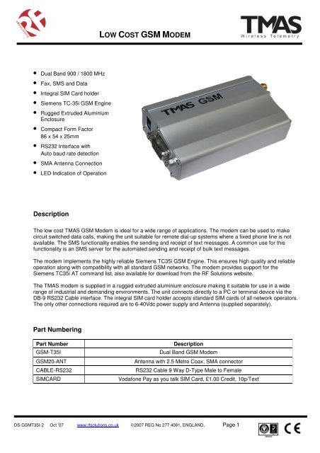
• Dual Band 900 / 1800 MHz<br />
• Fax, SMS and Data<br />
• Integral SIM Card holder<br />
• Siemens TC-35i <strong>GSM</strong> Engine<br />
• Rugged Extruded Aluminium<br />
Enclosure<br />
• Compact Form Factor<br />
86 x 54 x 25mm<br />
• RS232 Interface with<br />
Auto baud rate detection<br />
• SMA Antenna Connection<br />
• LED Indication of Operation<br />
Description<br />
<strong>LOW</strong> <strong>COST</strong> <strong>GSM</strong> <strong>MODEM</strong><br />
The low cost TMAS <strong>GSM</strong> Modem is ideal for a wide range of applications. The modem can be used to make<br />
circuit switched data calls, making the unit suitable for remote dial-up systems where a fixed phone line is not<br />
available. The SMS functionality enables the sending and receipt of text messages. A common use for this<br />
functionality is an SMS server for the automated sending and receipt of bulk text messages.<br />
The modem implements the highly reliable Siemens TC35i <strong>GSM</strong> Engine. This ensures high quality and reliable<br />
operation along with compatibility with all standard <strong>GSM</strong> networks. The modem provides support for the<br />
Siemens TC35i AT command list, also available for download from the RF Solutions website.<br />
The TMAS modem is supplied in a rugged extruded aluminium enclosure making it suitable for use in a wide<br />
range of industrial and demanding environments. The unit connects directly to a PC or terminal device via the<br />
DB-9 RS232 Cable interface. The integral SIM card holder accepts standard SIM cards of all network operators.<br />
The only other connections required are to 6-40Vdc power supply and Antenna (supplied separately).<br />
Part Numbering<br />
Part Number Description<br />
<strong>GSM</strong>-T35I Dual Band <strong>GSM</strong> Modem<br />
<strong>GSM</strong>20-ANT Antenna with 2.5 Metre Coax, SMA connector<br />
CABLE-RS232 RS232 Cable 9 Way D-Type Male to Female<br />
SIMCARD Vodafone Pay as you talk SIM Card, £1.00 Credit, 10p/Text<br />
DS-<strong>GSM</strong>T35I-2 Oct ’07 www.rfsolutions.co.uk ©2007 REG No 277 4001, ENGLAND. Page 1
Table of Contents<br />
<strong>LOW</strong> <strong>COST</strong> <strong>GSM</strong> <strong>MODEM</strong><br />
1 Key Features ..................................................................................................................................................3<br />
2 Interface description.......................................................................................................................................4<br />
2.1 Power Supply..................................................................................................................................4<br />
2.2 RS232 Interface..............................................................................................................................4<br />
2.3 SIM Interface ..................................................................................................................................5<br />
2.4 Radio Interface ...............................................................................................................................5<br />
3 Operating Modes............................................................................................................................................6<br />
3.1 Status LED......................................................................................................................................6<br />
4 Basic Setup Information .................................................................................................................................7<br />
4.1 Modem functionality Test................................................................................................................7<br />
4.2 Basic AT Command List.................................................................................................................9<br />
5 Mechanical Characteristics ..........................................................................................................................10<br />
DS-<strong>GSM</strong>T35I-2 Oct ’07 www.rfsolutions.co.uk ©2007 REG No 277 4001, ENGLAND. Page 2
1 Key Features<br />
<strong>LOW</strong> <strong>COST</strong> <strong>GSM</strong> <strong>MODEM</strong><br />
Features Implementation<br />
Transmission Data, SMS, Fax<br />
Power supply<br />
<strong>GSM</strong> class Small MS<br />
Frequency bands<br />
Transmit power<br />
SIM card reader Internal<br />
Single supply voltage<br />
Min: 6Vdc<br />
Max: 40Vdc<br />
• Dual Band E-<strong>GSM</strong> 900 and <strong>GSM</strong> 1800<br />
• Compliant to <strong>GSM</strong> Phase 2/2+<br />
• Class 4 (2W) for E<strong>GSM</strong>900<br />
• Class 1 (1W) for <strong>GSM</strong>1800<br />
External antenna Connected via antenna SMA connector<br />
SMS MT, MO, CB, Text and PDU mode<br />
CSD DATA<br />
FAX Group 3: Class 1, Class 2<br />
Serial interface<br />
Supported SIM card 3V<br />
• CSD transmission rates: 2.4, 4.8, 9.6, 14.4<br />
kbps, nontransparent,V.110<br />
• Unstructured Supplementary Services Data<br />
(USSD) support<br />
• RS-232 interface, bi-directional bus for AT<br />
commands and data<br />
• Multiplex ability according to <strong>GSM</strong> 07.10<br />
Multiplexer protocol<br />
• Baud rates from 300bps to 115,200bps<br />
• Autobauding supports: 1,200, 2,400, 4,800,<br />
9,600, 19,200, 38,400, 57,600 and 115,200bps<br />
Phonebook management Supported phonebook types: FD, LD, MC, RC, ON, ME<br />
Reset of Terminal TMAS <strong>GSM</strong> Reset via AT command<br />
Real time clock Implemented (clock frequency 32.768kHz)<br />
Environmental Temperature:<br />
• Normal operation: -20°C to +55°C<br />
• Humidity: max. 80% relative humidity<br />
Size 86mmx54mmx25mm (Casing Dimension)<br />
Weight 82g (Approx.)<br />
DS-<strong>GSM</strong>T35I-2 Oct ’07 www.rfsolutions.co.uk ©2007 REG No 277 4001, ENGLAND. Page 3
2 Interface description<br />
<strong>LOW</strong> <strong>COST</strong> <strong>GSM</strong> <strong>MODEM</strong><br />
The TMAS <strong>GSM</strong> Terminal provides the following connectors for power supply, interfacing and antenna:<br />
• 2.1mm DC power connector (centre/inner pin is positive)<br />
• 9-pin (female) D-SUB plug for RS-232 serial interface<br />
• SMA connector for antenna (radio interface)<br />
• SIM card holder<br />
2.1 Power Supply<br />
The power supply of the TMAS <strong>GSM</strong> Terminal has to be a single voltage source of Vin=6V providing a peak<br />
current of up to 500mA during transmission.<br />
The terminal can be turned on by just plug in a 6VDC power supply. The terminal power supply circuit<br />
automatically generates a low pulse signal not less than 100ms in order to wake up the Siemens TC35i <strong>GSM</strong><br />
engine.<br />
In order for the terminal to shut down properly, wait for 10s after sending AT^SMSO before switching off the<br />
power supply. This time is needed for the module to be safely logged off from the network and finish saving<br />
data to the internal memory.<br />
Each time the terminal is shut down, data will be written from the volatile memory to flash memory. The<br />
guaranteed maximum number of write cycles is limited to 100,000.<br />
2.2 RS232 Interface<br />
Via RS-232 interface, the host controller controls the TMAS <strong>GSM</strong>/GPRS Terminal and transports data. The<br />
table below shows the pin assignment of RS-232 (D-SUB 9-pin female).<br />
Pin no. Signal name I/O Function<br />
1 /DCD O Data Carrier Detected<br />
2 /RXD O Receive Data<br />
3 /TXD I Transmit Data<br />
4 /DTR I Data Terminal Ready<br />
5 GND - Ground<br />
6 /DSR O Data Set Ready<br />
7 /RTS I Request To Send<br />
8 /CTS O Clear To Send<br />
9 /RI O Ring Indication<br />
TMAS <strong>GSM</strong>/GPRS Terminal is designed for use as DCE. Based on the conventions for DCE-DTE connection,<br />
it communicates with the user application (DTE) using the following signals:<br />
DS-<strong>GSM</strong>T35I-2 Oct ’07 www.rfsolutions.co.uk ©2007 REG No 277 4001, ENGLAND. Page 4
<strong>LOW</strong> <strong>COST</strong> <strong>GSM</strong> <strong>MODEM</strong><br />
• Pin TxD @ application sends data to TxD of TMAS <strong>GSM</strong>/GPRS Terminal<br />
• Pin RxD @ application receives data from RxD of TMAS <strong>GSM</strong>/GPRS Terminal<br />
The RS-232 interface is implemented as a serial asynchronous transmitter and receiver conforming to ITU-T<br />
V.24 Interchange Circuits DCE. It is configured for 8 data bits, no parity and 1 stop bit, and can be operated at<br />
bit rates from 300bps to 115Kbps. Autobauding supports bit rates from 4.8Kbps to 115Kbps. Hardware<br />
handshake using the /RTS and /CTS signals and XON/XOFF software flow control are supported.<br />
In addition, the modem control signals /DTR, /DSR, /DCD and /RING are available. The modem control signal<br />
RING (Ring Indication) can be used to indicate to the cellular device application, that a call or Unsolicited Result<br />
Code (URC) is received. There are different modes of operation, which can be set with AT commands.<br />
2.3 SIM Interface<br />
The SIM interface is intended for 3V SIM cards in accordance with <strong>GSM</strong> 11.12 Phase 2. The card holder is a 5<br />
wire interface according to <strong>GSM</strong> 11.11. A sixth pin has been added to detect whether or not a SIM card is<br />
inserted.<br />
Removing and inserting the SIM card during operation requires the software to be reinitialized. Therefore, after<br />
reinserting the SIM card it is necessary to restart the terminal.<br />
Note:<br />
• No guarantee can be given, nor nay liability accepted, if loss of data is encountered after removing the<br />
SIM card during operation.<br />
• No guarantee can be given for properly initializing any SIM card that the user inserts after having<br />
removed a SIM card during operation. In this case, the application must restart the terminal.<br />
2.4 Radio Interface<br />
An internal RF cable is connected from the antenna reference point (antenna connector type GSC from Murata)<br />
to the SMA (female) connector. To attach the antenna to the TMAS <strong>GSM</strong>/GPRS Terminal, turn smoothly and<br />
slowly to the SMA (male) connector of antenna at clockwise direction.<br />
DS-<strong>GSM</strong>T35I-2 Oct ’07 www.rfsolutions.co.uk ©2007 REG No 277 4001, ENGLAND. Page 5
<strong>LOW</strong> <strong>COST</strong> <strong>GSM</strong> <strong>MODEM</strong><br />
Both single band and dual band antenna can be used for TMAS <strong>GSM</strong>/GPRS Terminal as long as it comes with<br />
the SMA (male) connector.<br />
3 Operating Modes<br />
The table below briefly summarizes the various operating modes of the TMAS <strong>GSM</strong> terminal<br />
Mode Function<br />
SLEEP Various power saving modes set by AT+CFUN command.<br />
Software is active to minimum extent. If the Terminal was registered to the <strong>GSM</strong><br />
network in IDLE mode, it remains, in SLEEP mode, registered and pageable from<br />
the BTS.<br />
Power saving can be chosen at different levels. The NON-CYCLIC SLEEP mode<br />
(AT+CFUN=0) disables the AT interface. The CYCLIC SLEEP mode AT+CFUN=5,<br />
6, 7 and 8 alternatively activate and deactivate the AT interface to allow permanent<br />
access to all AT commands.<br />
<strong>GSM</strong> IDLE Software is active. Once registered to the <strong>GSM</strong> network, paging with BTS<br />
Is carried out. The Terminal is ready to send and receive.<br />
<strong>GSM</strong> TALK Connection between two subscribers is in progress. Power consumption depends<br />
on network coverage individual settings, such as DTX off/on, FR/EFR/HR, hopping<br />
sequences, antenna.<br />
3.1 Status LED<br />
A red LED displays the operating status of the terminal.<br />
The table below summarizes the coding of the red LED status<br />
Operating status LED<br />
Power Down Off<br />
Not registered to the net (missing SIM, PIN, net) Fast Blinking<br />
Standby (registered to the net) Slow Flash (75ms On / 3s Off)<br />
Sleep mode (Power save mode, registered to the net) Off<br />
Talk mode, GPRS data On<br />
DS-<strong>GSM</strong>T35I-2 Oct ’07 www.rfsolutions.co.uk ©2007 REG No 277 4001, ENGLAND. Page 6
4 Basic Setup Information<br />
4.1 Modem functionality Test<br />
<strong>LOW</strong> <strong>COST</strong> <strong>GSM</strong> <strong>MODEM</strong><br />
On the first time power-up you can use terminal communications program to communicate with the modem<br />
through the RS-232 serial port. Following example is using the HyperTerminal in Windows XP.<br />
4.1.1 Select Hyperterminal from the Start Menu<br />
4.1.2 Start the HyperTerminal program and assign any name for a new session.<br />
DS-<strong>GSM</strong>T35I-2 Oct ’07 www.rfsolutions.co.uk ©2007 REG No 277 4001, ENGLAND. Page 7
<strong>LOW</strong> <strong>COST</strong> <strong>GSM</strong> <strong>MODEM</strong><br />
4.1.3 Choose the Com port connected to the modem. The unit features auto bauding so any baud rate from<br />
1.2 to 115.2 Kbps can be used, 8bits, no parity bit, 1 stop bit)<br />
4.1.4 On the terminal screen, type “AT” to check the “OK” response from the modem<br />
DS-<strong>GSM</strong>T35I-2 Oct ’07 www.rfsolutions.co.uk ©2007 REG No 277 4001, ENGLAND. Page 8
4.2 Basic AT Command List<br />
<strong>LOW</strong> <strong>COST</strong> <strong>GSM</strong> <strong>MODEM</strong><br />
The commands in the table below can be used for basic control of the <strong>GSM</strong> modem.<br />
Description AT commands Modem response Comments<br />
Network Registration<br />
Checking<br />
AT+CREG? CREG=,1 Modem registered to the network<br />
CREG=,2 Registration lost, re-registration<br />
attempt<br />
CREG=,0 Modem not registration on the<br />
network, no registration attempt<br />
Receiving signal AT+CSQ +CSQ: 20,0 The first parameter has to be at<br />
strength<br />
least 15 for normal communication<br />
Receiving an<br />
incoming call<br />
RING An incoming call is waiting<br />
ATA<br />
OK<br />
Answer the call<br />
Make a call ATD1234567; Don’t forget the « ; » at the end for<br />
« voice » call<br />
Make an emergency<br />
call<br />
OK Communication established<br />
CME ERROR : 11 PIN code not entered (with + CMEE<br />
= 1 mode)<br />
CME ERROR : 3 AOC credit exceeded or a<br />
communication is already<br />
established<br />
CME ERROR : 10 Cannot read the SIM card<br />
ATD 112; Don’t forget the « ; » at the end for<br />
« voice » call<br />
OK<br />
Communication loss NO CARRIER<br />
Hang up ATH<br />
OK<br />
Enter PIN code AT+CPIN=1234<br />
OK PIN Code accepted<br />
Saves parameters in<br />
non-volatile memory<br />
AT&W<br />
+CME ERROR : 16 Incorrect PIN Code (with +CMEE =<br />
1 mode)<br />
+CME ERROR : 3 PIN already entered (with +CMEE =<br />
1 mode)<br />
OK The configuration settings are<br />
stored<br />
DS-<strong>GSM</strong>T35I-2 Oct ’07 www.rfsolutions.co.uk ©2007 REG No 277 4001, ENGLAND. Page 9
5 Mechanical Characteristics<br />
<strong>LOW</strong> <strong>COST</strong> <strong>GSM</strong> <strong>MODEM</strong><br />
Weight 82g<br />
Dimension 86mmx54mmx25mm<br />
Temperature range -20°C to +55°C<br />
Air humidity Maximum 80% relative humidity<br />
Casing material Aluminium alloy<br />
For more information or general enquiries contact:<br />
R F Solutions Ltd.<br />
Unit 21, Cliffe Industrial Estate,<br />
South Street, Lewes, BN8 6JL, England.<br />
Email: sales@rfsolutions.co.uk Web: http://www.rfsolutions.co.uk<br />
Tel: +44 (0)1273 898 000 Fax: +44 (0)1273 480 661<br />
DS-<strong>GSM</strong>T35I-2 Oct ’07 www.rfsolutions.co.uk ©2007 REG No 277 4001, ENGLAND. Page 10