Rixson Duo Floor Closer Installation Instructions - Epivots
Rixson Duo Floor Closer Installation Instructions - Epivots
Rixson Duo Floor Closer Installation Instructions - Epivots

You also want an ePaper? Increase the reach of your titles
YUMPU automatically turns print PDFs into web optimized ePapers that Google loves.
®<br />
RIXSON<br />
ASSA ABLOY<br />
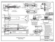
Template<br />
1-7/16<br />
1-1/32<br />
7/8" Dia. Hole<br />
Jamb<br />
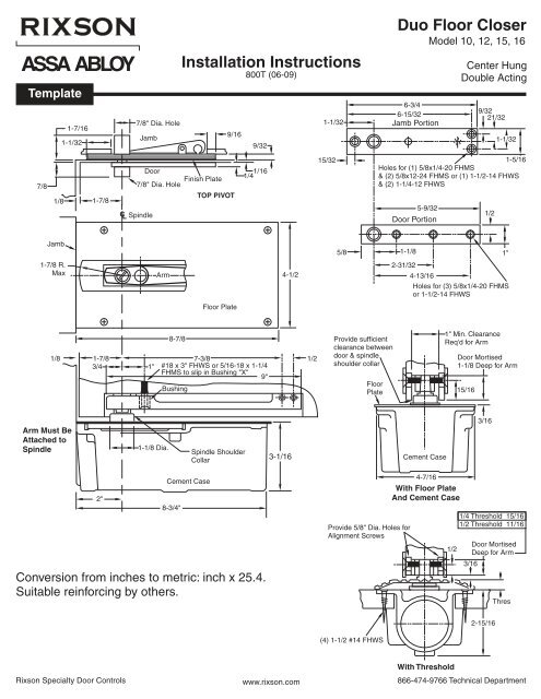
<strong>Installation</strong> <strong>Instructions</strong><br />
800T (06-09)<br />
9/16<br />
9/32<br />
1-1/32<br />
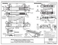
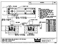
<strong>Duo</strong> <strong>Floor</strong> <strong>Closer</strong><br />
Model 10, 12, 15, 16<br />
6-3/4<br />
6-15/32<br />
Jamb Portion<br />
Center Hung<br />
Double Acting<br />
7/8<br />
1/8<br />
1-7/8<br />
Door<br />
Finish Plate<br />
7/8" Dia. Hole<br />
TOP PIVOT<br />
C L Spindle<br />
1/16<br />
1/4<br />
15/32<br />
9/32<br />
21/32<br />
1-1/32<br />
1-5/16<br />
Holes for (1) 5/8x1/4-20 FHMS<br />
& (2) 5/8x12-24 FHMS or (1) 1-1/2-14 FHWS<br />
& (2) 1-1/4-12 FHWS<br />
5-9/32<br />
Door Portion<br />
1/2<br />
Jamb<br />
5/8 1-1/8<br />
1"<br />
1-7/8 R.<br />
Max<br />
Arm<br />
4-1/2<br />
2-31/32<br />
4-13/16<br />
Holes for (3) 5/8x1/4-20 FHMS<br />
or 1-1/2-14 FHWS<br />
<strong>Floor</strong> Plate<br />
8-7/8<br />
1/8 1-7/8 7-3/8 1/2<br />
3/4<br />
1" #18 x 3" FHWS or 5/16-18 x 1-1/4<br />
FHMS to slip in Bushing "X"<br />
9"<br />
Bushing<br />
Provide sufficient<br />
clearance between<br />
door & spindle<br />
shoulder collar<br />
<strong>Floor</strong><br />
Plate<br />
1" Min. Clearance<br />
Req'd for Arm<br />
Door Mortised<br />
1-1/8 Deep for Arm<br />
15/16<br />
Arm Must Be<br />
Attached to<br />
Spindle<br />
1-1/8 Dia.<br />
Spindle Shoulder<br />
Collar<br />
3-1/16<br />
Cement Case<br />
3/16<br />
2"<br />
Cement Case<br />
8-3/4"<br />
Conversion from inches to metric: inch x 25.4.<br />
Suitable reinforcing by others.<br />
Provide 5/8" Dia. Holes for<br />
Alignment Screws<br />
4-7/16<br />
With <strong>Floor</strong> Plate<br />
And Cement Case<br />
1/2<br />
1/4 Threshold 15/16<br />
1/2 Threshold 11/16<br />
Door Mortised<br />
Deep for Arm<br />
3/16<br />
Thres<br />
2-15/16<br />
(4) 1-1/2 #14 FHWS<br />
With Threshold<br />
<strong>Rixson</strong> Specialty Door Controls www.rixson.com 866-474-9766 Technical Department
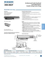
PAGE 2<br />
Face of Jamb<br />
WARNING: Do not strike closer with a hammer. The closer<br />
can be made completely inoperative by denting the closer<br />
tube with a hammer blow.<br />
1-3/32<br />
2-3/16<br />
Center<br />
of Spindle 1-9/16<br />
3-1/8<br />
1-7/8<br />
15/16<br />
1-9/16<br />
2"<br />
2-5/8<br />
DOOR MUST NOT BE PERMITTED TO OPEN BEYOND<br />
105°.<br />
Top Pivot Jamb Portion<br />
Top Pivot Door Portion<br />
Centerline<br />
Between Jambs<br />
6-1/8<br />
Bushing (X)<br />
Alignment Screws<br />
1-5/8<br />
13/16<br />
3/4 Dia. Typ.<br />
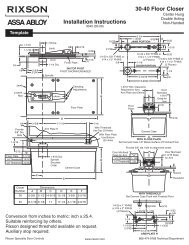
<strong>Installation</strong> <strong>Instructions</strong><br />
1. Locating <strong>Closer</strong><br />
Door<br />
Jamb<br />
Spindle Position<br />
Centerline of Door<br />
and Spindle<br />
2” From Face of<br />
Jamb to C L of Spindle<br />
A. Measure 2” out from door jamb on centerline of door. This<br />
is the location of the spindle center.<br />
2. Install <strong>Closer</strong> in <strong>Floor</strong><br />
LEVEL IN BOTH<br />
DIRECTIONS<br />
A. For floor plate application: the top of the closer case (or<br />
cement case as both are the same level) is set 1/16"<br />
below finished floor.<br />
B. For threshold application: the closer case is set flush with<br />
the finished floor.<br />
C. CEMENT FLOOR INSTALLATION:<br />
1. Set Cement case in floor and block in position.<br />
2. Case should be parallel with centerline of door.<br />
3. CEMENT CASE SHOULD BE LEVEL. Place levels per<br />
illustration.<br />
4. Grout in cement case with closer. Cement should not<br />
get between closer and case.<br />
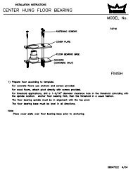
D. WOOD FLOOR INSTALLATION:<br />
1. Locate center line of closer 2" out from face of frame.<br />
Using dimensioned outline of closer locate and bore (8)<br />
3/4" diameter holes. Cut out the floor using these bored<br />
holes and the dimensioned outline as a guide.<br />
2. Place arm on spindle of closer<br />
and set closer into opening, with Door Bushing (x)<br />
center of arm on line with center<br />
to C L of spindle<br />
of door. Draw a line around<br />
on C L of door<br />
overlapping square top of casting.<br />
Spindle<br />
Mortise for this overlap allowing<br />
1/16" for floor plate thickness. Top of closer case will be<br />
1/16" below finished floor.<br />
3. CLOSER CASE SHOULD BE LEVEL. Place levels per<br />
illustration.<br />
4. Fasten closer securely with screws furnished.<br />
5. Place floor plate on closer, mark around it and mortise<br />
into floor. Fasten with screws furnished.<br />
<strong>Rixson</strong> Specialty Door Controls www.rixson.com 866-474-9766 Technical Department
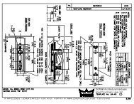
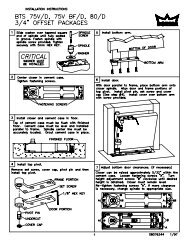
3. Install Top Pivot and <strong>Closer</strong> Arm<br />
PAGE 3<br />
A. Install top pivot in door per template.<br />
B. Install top pivot in jamb per template.<br />
C. Centerline of pivot should line up with centerline of<br />
closer. Use a plumb line to assure accuracy.<br />
D. Mortise door to receive arm. (Mortise varies if<br />
threshold is used–refer to template).<br />
E. Secure bushing to bottom of door with screw<br />
furnished.<br />
F. Drill two 5/8" holes for alignment screws.<br />
4. Hang Door<br />
Top Pivot<br />
Pin<br />
Centerline<br />
of Door<br />
Pin Retracting<br />
Screw<br />
A. Turn valve screw down. NEVER FORCE VALVE<br />
SCREW DOWN AS THIS WILL DAMAGE TIP<br />
SEATING.<br />
B. Fasten arm to closer spindle then turn spindle right<br />
(or left) until spindle and arm reach a door opening<br />
position of about 30°.<br />
C. Set door on arm and engage the top pivot pin by<br />
turning pin retracting screw up.<br />
D. Turn in arm alignment screws lightly.<br />
E. Open stroke valve (counter-clockwise) one turn.<br />
F. Adjust arm alignment screws until door rests in<br />
center of doorway.<br />
30°<br />
Adjusting Screw<br />
Alignment Screws<br />
<strong>Rixson</strong> Specialty Door Controls www.rixson.com 866-474-9766 Technical Department
<strong>Closer</strong> Adjustment<br />
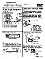
PAGE 4<br />
Closing speeds can be adjusted to suit local conditions and<br />
requirements. Turn the adjusting screw that projects<br />
through the floor plate or threshold, either in or out as the<br />
case may be until the desired action is attained. Turn this<br />
valve screw to the right, clockwise, to decrease closing<br />
speed and to the left to increase the closing speed.<br />
FORCING THIS SCREW DOWN WILL IMPAIR ITS<br />
OPERATION.<br />
Spring Power Adjustments<br />
There is no spring power adjustment. If the spring power is<br />
not adequate a heavier duo-check should be installed. All<br />
duo-checks PH10, PH12, 15, 16 are interchangeable.<br />
<strong>Rixson</strong>® is a registered trademark of Yale Security Inc., an ASSA ABLOY Group company. Copyright© 2002, 2009, Yale Security Inc., an ASSA ABLOY Group company.<br />
All rights reserved. Reproduction in whole or in part without the express written permission of Yale Security Inc. is prohibited.<br />
RIXSON®<br />
ASSA ABLOY<br />
<strong>Rixson</strong> Specialty Door Controls www.rixson.com 866-474-9766 Technical Department