CoolMOS Power MOSFET in ECO-PAC 2
CoolMOS Power MOSFET in ECO-PAC 2
CoolMOS Power MOSFET in ECO-PAC 2

Create successful ePaper yourself
Turn your PDF publications into a flip-book with our unique Google optimized e-Paper software.
VHM 40-06P1<br />
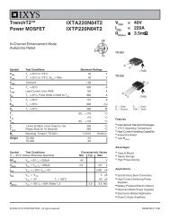
<strong>CoolMOS</strong> <strong>Power</strong> <strong>MOSFET</strong><br />
<strong>in</strong> <strong>ECO</strong>-<strong>PAC</strong> 2<br />
N-Channel Enhancement Mode<br />
Low R DSon , High V DSS <strong>MOSFET</strong><br />
Package with Electrically Isolated Base<br />
I D25 = 38 A<br />
V DSS = 600 V<br />
R DSon = 70 mΩ<br />
1)<br />
Prelim<strong>in</strong>ary data<br />
L 4<br />
L 6<br />
K 12<br />
L 9<br />
NTC<br />
P 18<br />
R 18<br />
F 10<br />
K 13<br />
X 15<br />
T 18<br />
V 18<br />
X 18<br />
K 10<br />
P<strong>in</strong> arrangement see outl<strong>in</strong>es<br />
<strong>MOSFET</strong><br />
Symbol Conditions Maximum Rat<strong>in</strong>gs<br />
V DSS T VJ = 25°C to 150°C 600 V<br />
V GS<br />
± 20 V<br />
I D25<br />
I D90<br />
T C = 25°C<br />
T C = 90°C<br />
d V /dt<br />
V DS < V DSS ; I F < 50 A; | di F /dt | < 200 A/µs<br />
T VJ = 150°C<br />
E AS<br />
E AR<br />
I D = 10 A; T C = 25°C<br />
I D = 20 A; T C = 25°C<br />
38<br />
25<br />
1.8<br />
1<br />
A<br />
A<br />
6 V/ns<br />
Symbol Conditions Characteristic Values<br />
J<br />
mJ<br />
(T VJ = 25°C, unless otherwise specified)<br />
m<strong>in</strong>. typ. max.<br />
R DSon V GS = 10 V; I D = I D90 70 mW<br />
V GS(th) V DS = 20 V; I D = 3 mA 3.5 5.5 V<br />
I DSS V DS = V DSS ; V GS = 0 V; T VJ = 25°C<br />
25 µA<br />
T VJ = 125°C 60<br />
µA<br />
I GSS V GS = ± 20 V; V DS = 0 V 100 nA<br />
Q g<br />
Q gs<br />
Q gd<br />
t d(on)<br />
t r<br />
t d(off)<br />
t f<br />
V GS = 10 V; V DS = 350 V; I D = 50 A<br />
V GS = 10 V; V DS = 380 V<br />
I D = 25 A; R G = 1.8 Ω<br />
220<br />
55<br />
125<br />
30<br />
95<br />
100<br />
10<br />
R thJC per <strong>MOSFET</strong> 0.45 K/W<br />
Data accord<strong>in</strong>g ot IEC 60747 refer to a s<strong>in</strong>gle diode or transistor unless otherwise stated<br />
nC<br />
nC<br />
nC<br />
ns<br />
ns<br />
ns<br />
ns<br />
Applications<br />
• <strong>ECO</strong>-<strong>PAC</strong> 2 with DCB Base<br />
- Electrical isolation towards the heats<strong>in</strong>k<br />
- Low coupl<strong>in</strong>g capacitance to the<br />
heats<strong>in</strong>k for reduced EMI<br />
- High power dissipation<br />
- High temperature cycl<strong>in</strong>g capability<br />
of chip on DCB<br />
- solderable p<strong>in</strong>s for DCB mount<strong>in</strong>g<br />
• fast <strong>CoolMOS</strong> power <strong>MOSFET</strong><br />
- High block<strong>in</strong>g capability<br />
- Low on resistance<br />
- Avalanche rated for unclamped<br />
<strong>in</strong>ductive switch<strong>in</strong>g (UIS)<br />
- Low thermal resistance<br />
due to reduced chip thickness<br />
• Enhanced total power density<br />
Applications<br />
• Switched mode power supplies (SMPS)<br />
• Un<strong>in</strong>terruptible power supplies (UPS)<br />
• <strong>Power</strong> factor correction (PFC)<br />
• Weld<strong>in</strong>g<br />
• Inductive heat<strong>in</strong>g<br />
1) <strong>CoolMOS</strong> is a trademark of Inf<strong>in</strong>eon Technologies AG.<br />
IXYS reserves the right to change limits, test conditions and dimensions.<br />
© IXYS 2009 All rights reserved<br />
20091214a<br />
1 - 3
VHM 40-06P1<br />
Source-Dra<strong>in</strong> Diode<br />
Symbol Conditions Characteristic Values<br />
(T VJ = 25°C, unless otherwise specified)<br />
m<strong>in</strong>. typ. max.<br />
I S Inverse diode forward current 47 A<br />
I SM Inverse diode direct current pulsed 141 A<br />
V SD<br />
t rr<br />
Inverse diode forward voltage<br />
1 1.2 V<br />
V GS = 0 V; I F = I S<br />
580 ns<br />
Q rr<br />
V R = 350 V<br />
23 µC<br />
I RM<br />
I F = I S<br />
di F /dt = 100 A/µs<br />
73 A<br />
di rr /dt 900 A/µs<br />
Reverse diodes (FRED)<br />
Symbol Conditions Maximum Rat<strong>in</strong>gs<br />
I F25<br />
I F80<br />
T = 25°C<br />
T = 80°C<br />
18.5<br />
12.0<br />
Symbol Conditions Characteristic Values<br />
V F<br />
I F = 15 A; T = 25°C<br />
T = 125°C<br />
I RM<br />
t rr<br />
I F = 10 A; di F /dt = 400 A/µs; T = 125°C<br />
V R = 300 V; V GE = 0 V<br />
m<strong>in</strong>. typ. max.<br />
11.2<br />
11.2<br />
7<br />
70<br />
R thJC<br />
R thJH with heats<strong>in</strong>k compound (0.42 K/m.K; 50 µm) 7<br />
A<br />
A<br />
mm<br />
mm<br />
A<br />
ns<br />
0.35 K/W<br />
K/W<br />
Temperature Sensor NTC<br />
Symbol Conditions Characteristic Values<br />
m<strong>in</strong>. typ. max.<br />
R 25 T = 25°C 4.75 5.0<br />
B 25/50 3375<br />
5.25 kΩ<br />
K<br />
Module<br />
Symbol Conditions Maximum Rat<strong>in</strong>gs<br />
T VJ<br />
T stg<br />
-40...+150<br />
-40...+125<br />
V ISOL I ISOL < 1 mA; 50/60 Hz; t = 1 s 3600 V~<br />
M d mount<strong>in</strong>g torque (M4) 1.5 - 2.0<br />
14 - 18<br />
°C<br />
°C<br />
Nm<br />
lb.<strong>in</strong><br />
a Max. allowable acceleration 50 m/s 2<br />
Symbol Conditions Characteristic Values<br />
d S<br />
d A<br />
Creepage distance on surface (p<strong>in</strong> to heats<strong>in</strong>k)<br />
Strike distance <strong>in</strong> air (p<strong>in</strong> to heats<strong>in</strong>k)<br />
© IXYS 2009 All rights reserved<br />
m<strong>in</strong>. typ. max.<br />
11.2<br />
11.2<br />
mm<br />
mm<br />
Weight 24 g<br />
20091214a<br />
2 - 3
VHM 40-06P1<br />
Dimensions <strong>in</strong> mm (1 mm = 0.0394")<br />
© IXYS 2009 All rights reserved<br />
20091214a<br />
3 - 3