THYRISTOR MODULES Medium power general use Insulated type
THYRISTOR MODULES Medium power general use Insulated type
THYRISTOR MODULES Medium power general use Insulated type

Create successful ePaper yourself
Turn your PDF publications into a flip-book with our unique Google optimized e-Paper software.
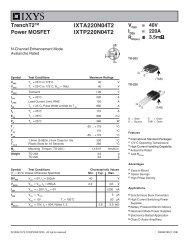
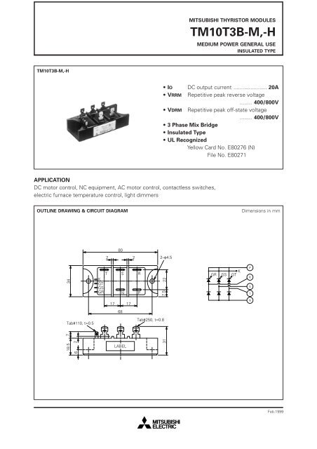
MITSUBISHI <strong>THYRISTOR</strong> <strong>MODULES</strong>TM10T3B-M,-HMEDIUM POWER GENERAL USEINSULATED TYPETM10T3B-M,-H• IO DC output current ...................... 20A• VRRM Repetitive peak reverse voltage........ 400/800V• VDRM Repetitive peak off-state voltage........ 400/800V• 3 Phase Mix Bridge• <strong>Insulated</strong> Type• UL RecognizedYellow Card No. E80276 (N)File No. E80271APPLICATIONDC motor control, NC equipment, AC motor control, contactless switches,electric furnace temperature control, light dimmersOUTLINE DRAWING & CIRCUIT DIAGRAMDimensions in mm802 22–φ4.534T S RKGTGSGR N P227.5KGR GS GTPRST17 17N68Tab#110, t=0.5Tab#250, t=0.818.5 726LABEL31Feb.1999
MITSUBISHI <strong>THYRISTOR</strong> <strong>MODULES</strong>TM10T3B-M,-HMEDIUM POWER GENERAL USEINSULATED TYPEABSOLUTE MAXIMUM RATINGSSymbolParameterMVoltage classHUnitVRRMRepetitive peak reverse voltage400800VVRSMNon-repetitive peak reverse voltage480960VVR (DC)DC reverse voltage320640VVDRMRepetitive peak off-state voltage400800VVDSMNon-repetitive peak off-state voltage480960VVD (DC)DC off-state voltage320640VSymbolParameterConditionsRatingsUnitIODC output current3-phase fullwave rectified, TC=79°C20AITSM, IFSMI 2 tSurge (non-repetitive) currentI 2 t for fusingOne half cycle at 60Hz, peak valueValue for one cycle of surge current2001.7 × 10 2AA 2 sdi/dtCritical rate of rise of on-state currentVD=1/2VDRM, IG=0.5A, Tj=125°C50A/µsPGMPeak gate <strong>power</strong> dissipation5.0WPG (AV)Average gate <strong>power</strong> dissipation0.5WVFGMPeak gate forward voltage10VVRGMPeak gate reverse voltage5.0VIFGMPeak gate forward current2.0ATjJunction temperature–40~125°CTstgStorage temperature–40~125°CVisoIsolation voltageCharged part to case2500V—Mounting torqueMounting screw M40.98~1.4710~15N·mkg·cm—WeightTypical value130gELECTRICAL CHARACTERISTICSSymbolParameterTest conditionsMin.LimitsTyp.Max.UnitIRRMIDRMVTM, VFMdv/dtVGTVGDIGTRth (j-c)Rth (c-f)Repetitive peak reverse currentRepetitive peak off-state currentForward voltageCritical rate of rise of off-state voltageGate trigger voltageGate non-trigger voltageGate trigger currentThermal resistanceContact thermal resistanceTj=125°C, VRRM appliedTj=125°C, VDRM appliedTj=125°C, ITM=IFM=20A, instantaneous meas.Tj=125°C, VD=2/3VDRMTj=25°C, VD=6V, RL=2ΩTj=125°C, VD=1/2VDRMTj=25°C, VD=6V, RL=2ΩJunction to case (per 1/6 module)Case to fin, Conductive grease applied (per 1/6 module)———500—0.2510———————————4.04.01.3—2.0—504.50.6mAmAVV/µsVVmA°C/W°C/W—Insulation resistanceMeasured with a 500V megohmmeter between main terminaland case10——MΩNote: Items of the above table applies to the Thyristor part and the Diode part as circled in the following tables.Feb.1999
MITSUBISHI <strong>THYRISTOR</strong> <strong>MODULES</strong>TM10T3B-M,-HMEDIUM POWER GENERAL USEINSULATED TYPEMAXIMUM RATINGSItemVRRM VRSM VR (DC) VDRMVDSMVD (DC)IT (RMS)IF (RMS)IT (AV)IF (AV)ITSMIFSMI 2 tdi/dtThyristorDiode————ItemPGMPG (AV)VFGMIFGMTjTstgThyristorDiode————ELECTRICAL CHARACTERISTICSItemIRRMIDRMVTMVFMdv/dtVGTVGDIGTRth (j-c)Rth (c-f)ThyristorDiode—————PERFORMANCE CURVESMAXIMUM FORWARD CHARACTERISTICRATED SURGE (NON-REPETITIVE)CURRENTCURRENT (A)10 3753210 27532Tj=125°CSURGE (NON-REPETITIVE)CURRENT (A)200160120804010 10.8 1.0 1.2 1.4 1.6 1.8FORWARD VOLTAGE (V)01 2 3 5 7 10 20 30 50 70100CONDUCTION TIME(CYCLE AT 60Hz)Feb.1999
MITSUBISHI <strong>THYRISTOR</strong> <strong>MODULES</strong>TM10T3B-M,-HMEDIUM POWER GENERAL USEINSULATED TYPEMAXIMUM TRANSIENT THERMALIMPEDANCE (JUNCTION TO CASE)(PER SINGLE ELEMENT)MAXIMUM POWER DISSIPATION(THREE PHASE FULLWAVE RECTIFIED)TRANSIENT THERMAL IMPEDANCE(°C/W)10 0 2 3 5 71015.04.03.02.01.0POWER DISSIPATION (W)8070605040302010RESISTIVE, INDUCTIVE LOADθ=30°60°120°90°010 –3 2 3 5 710 –2 2 3 5 7 10 –1 2 3 5 710 00 0 5 10 15 20TIME (s)DC OUTPUT CURRENT(A)LIMITING VALUE OF THE DC OUTPUT CURRENT(THREE PHASE FULLWAVE RECTIFIED)CASE TEMPERATURE (°C)130120110100908070605040θ=30° 60° 90° 120°30 0 5 10 15 20DC OUTPUT CURRENT (A)Feb.1999