model t24100 1 hp 230v 1-phase magnetic switch - Grizzly.com
model t24100 1 hp 230v 1-phase magnetic switch - Grizzly.com
model t24100 1 hp 230v 1-phase magnetic switch - Grizzly.com

You also want an ePaper? Increase the reach of your titles
YUMPU automatically turns print PDFs into web optimized ePapers that Google loves.
MODEL T24100<br />
1 HP 230V 1-PHASE<br />
MAGNETIC SWITCH<br />
INSTRUCTIONS<br />
Electrocution or fire<br />
could occur if this<br />
<strong>switch</strong> is not installed<br />
by an electrician or<br />
qualified service personnel!<br />
230 Volt<br />
Single-Phase<br />
Power Source<br />
1L1<br />
3L2 5L3 13NO<br />
Contactor TECO<br />
CU-16 (230V Coil)<br />
TECO<br />
CU-<br />
16<br />
NO<br />
53<br />
ON<br />
54<br />
NO<br />
Ground<br />
COLOR KEY<br />
BLACK<br />
GREEN<br />
RED<br />
YELLOW<br />
Bk<br />
Gn<br />
Rd<br />
2T1 4T2 6T3 14NO<br />
Thermal Overload<br />
Relay TECO RHU-10K1<br />
(7.2–10A)<br />
TRIP IND.<br />
TEST<br />
O R<br />
A<br />
OFF RESET<br />
97 NO 98 NO 95 NC 96 NC<br />
2T1 4T2 6T3<br />
M<br />
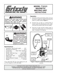
Figure 1. Model T24100 <strong>magnetic</strong><br />
<strong>switch</strong>.<br />
1 HP 230V Motor<br />
OPERATION: When pushed, the green ON button on the outside cover of the <strong>magnetic</strong> <strong>switch</strong> energizes<br />
a <strong>magnetic</strong> coil, which pulls the contactor closed. The main current then passes through the contactor<br />
and thermal overload relay to the motor. The red OFF button breaks the <strong>magnetic</strong> field, which opens the<br />
contactor and disconnects the current to the motor. A motor overload or an interruption of the power supply<br />
will also break the <strong>magnetic</strong> field and release the contactor and disconnect current to the motor. The motor<br />
will not re-start until the overload is reset and/or the ON button is pushed.<br />
Copyright © October, 2011 By <strong>Grizzly</strong> Industrial, Inc.<br />
Warning: No portion of this manual may be reproduced in any shape<br />
Or form without the written approval of <strong>Grizzly</strong> Industrial, inc.<br />
#ST14413 printed in TAIWAN
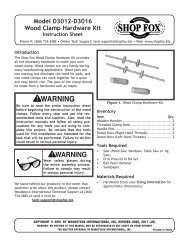
Thermal Relay Overload Amp<br />
Adjustment Dial: Turn this dial<br />
to the amperage setting specified<br />
by the motor manufacturer.<br />
Typically, this setting is 100–<br />
110% of the amperage load listed<br />
on the motor data plate. Please<br />
note that turning this dial has<br />
no effect on increasing motor<br />
horsepower. If turned too high,<br />
the motor can overheat and be<br />
damaged before the relay trips.<br />
Trip Indicator: If this window<br />
turns yellow, the thermal relay<br />
has tripped.<br />
Manual Contactor Override<br />
Lug: When pushed, the contactor<br />
is manually closed for troubleshooting<br />
purposes only.<br />
ON Button: When pushed,<br />
power is sent to the <strong>magnetic</strong><br />
field coil, closing the contactor<br />
and sending power to the motor.<br />
Manual/Auto Reset Lever: In<br />
the up position, the thermal relay<br />
is in manual reset mode. This<br />
means you must re-install the<br />
outside cover and push the red<br />
OFF button, then push the green<br />
ON button to reset the thermal<br />
relay. In the down position, the<br />
thermal relay will automatically<br />
reset when it has cooled.<br />
Manual Trip Test Lever: If the<br />
thermal relay function is in question,<br />
run the motor and use a<br />
wooden toot<strong>hp</strong>ick to slide the<br />
yellow test lever to the left. If the<br />
motor shuts off, the thermal relay<br />
has tripped and is functional.<br />
Reset Button: When pushed,<br />
the thermal relay is reset, clearing<br />
the yellow trip indicator window.<br />
OFF Button: When pushed, the current going to the <strong>magnetic</strong> field<br />
coil is cut, which opens the contactor and cuts power to the motor.<br />
10<br />
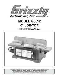
Parts Breakdown<br />
3<br />
4<br />
8<br />
12<br />
11<br />
6<br />
7<br />
1<br />
9<br />
5<br />
2<br />
Parts breakdown provided for reference only. Not all parts shown are available for purchase.<br />
REF DESCRIPTION REF DESCRIPTION<br />
1 SWITCH BOX 7 PHLP HD SCR M3-.5 X 10<br />
2 SWITCH BOX COVER ASSEMBLY 8 CAPTURED GROUND SCR M4-.7 X 10<br />
3 CONTACTOR TECO CU-16 230V 9 PHLP HD SCR 10-24 X 1-1/2<br />
4 FIELD SWITCH TECO CNA-1 10 LIQUID-TITE STRAIN RELIEF<br />
5 OL RELAY TECO RHU-10K1 7.2-10A 11 RUBBER SEAL<br />
6 GROUNDING PLATE 12 PLASTC SCREW M10-1.5 X 20 GRAY<br />
-2- T24100 Magnetic Switch