Eaton Axle and Brake Service Manual. Single Reduction Axles with ...
Eaton Axle and Brake Service Manual. Single Reduction Axles with ...
Eaton Axle and Brake Service Manual. Single Reduction Axles with ...

Create successful ePaper yourself
Turn your PDF publications into a flip-book with our unique Google optimized e-Paper software.
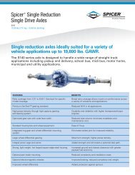
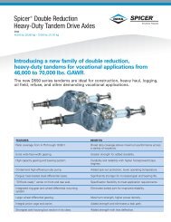
Spicer ® <strong>Single</strong> Drive <strong>Axle</strong>s<br />
<strong>Service</strong> <strong>Manual</strong><br />
AXSM0047<br />
September 2007
Spicer <strong>Axle</strong> <strong>Service</strong> <strong>and</strong> Maintenance Instructions<br />
Spicer Controlled Traction Differentials<br />
Introduction<br />
Dana presents this publication to aid in<br />
maintenance <strong>and</strong> overhaul of Spicer<br />
single reduction axles equipped <strong>with</strong> a<br />
biasing-type, controlled traction differential.<br />
In this manual, this unit is termed Controlled<br />
Traction Differential (or CTD).<br />
Two design types are available: mediumduty<br />
<strong>and</strong> heavy-duty.<br />
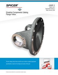
Medium-duty CTD.<br />
Designed for singledrive<br />
axels 19,000 to<br />
22,000 lbs. <strong>and</strong><br />
tadems 34,000 to<br />
45,000 lbs. capacity<br />
(see chart below).<br />
In this manual, instructions for both CTD<br />
design types are the same except where<br />
specified otherwise. This manual includes<br />
specific instructions for single reduction,<br />
differential carriers (both single drive <strong>and</strong><br />
t<strong>and</strong>em axles) equipped <strong>with</strong> Controlled<br />
Traction Differentials. For service instructions<br />
covering other axle parts <strong>and</strong> adjustments,<br />
refer to the appropriate Spicer axle service<br />
manuals (see back cover).<br />
Medium-duty CTD.<br />
Designed for singledrive<br />
axels 23,000 to<br />
30,000 lbs. <strong>and</strong><br />
tadems 44,000 to<br />
52,000 lbs. capacity<br />
(see chart below).<br />
Driver-Controlled<br />
Type Illustrated.<br />
Controlled<br />
Traction Differential (CTD) Applications<br />
<strong>Axle</strong> Models<br />
Medium Duty CTD<br />
Friction Plates (qty.)<br />
Clutch Pack Kit<br />
17401, 17421, 21421, 22421 (8) Splined O.D. (7) Splined I.D. Total Plates 15<br />
DC381 (P), DC401-P Part No. 111027 Part No. 111028 Part No. 118291<br />
DC402(P), DC451-P<br />
Heavy Duty CTD<br />
23105C, 26105C, 30105C (9) Tanged O.D. (8) Splined I.D. Total Plates 17<br />
Part No. 113972 Part No, 113971 Part No. 121704<br />
*23421 , 26421, 23085 (13) Tanged O.D. (12) Splined I.D. *Total Plates 25<br />
DC460-P, DC480-P Part No. 82446 Part No, 82445 Part No. 211361<br />
DC461-P, DC521-P<br />
(11) Tanged O.D. (10) Splined I.D. *Total Plates 21<br />
Part No, 82446 Part No. 82445 Part No, 084827<br />
*NOTE: Original equipped clutch pack may Include 21 or 25 friction plates. The packs are Interchangeable.<br />
Individual plates are identical in both clutch packs. The 25-plate clutch pack will produce a higher biasing<br />
torque. Spicer recommends using the 25-plate clutch pack for replacement.<br />
2 Price $3.50
Contents<br />
Model Variations<br />
Description <strong>and</strong> Operation.<br />
Checking Effectiveness of Controlled Traction Differential<br />
Clutch Pack Lubrication<br />
Driver-Controlled CTD Shift Unit<br />
CTD Adjustments<br />
Shifting Seasonal CAD<br />
Fastener Tightening Specifications<br />
All Types<br />
Remove Differential Carrier Assembly from <strong>Axle</strong> Housing<br />
Remove Differential <strong>and</strong> Clutch Pack Assembly from Carrier<br />
Medium-Duty CTD<br />
Remove <strong>and</strong> Disassemble Clutch Pack<br />
Assemble <strong>and</strong> install Clutch Pack<br />
Heavy-Duty CTD<br />
Remove <strong>and</strong> Disassemble Clutch Pack .<br />
Assemble <strong>and</strong> install Clutch Pack<br />
All Types<br />
install Differential <strong>and</strong> Clutch Pack Assembly in Carrier<br />
Adjust Differential Bearing Preload<br />
Install Differential Carrier Assembly in <strong>Axle</strong> Housing<br />
Functional CTD Check (After Repair or Overhaul)<br />
Driver-Controlled Type<br />
CTD Shift System (<strong>Single</strong> <strong>Axle</strong>s)<br />
Troubleshooting (<strong>Single</strong> <strong>Axle</strong>s)<br />
CTD Shift System (T<strong>and</strong>em <strong>Axle</strong>s)<br />
Troubleshooting (T<strong>and</strong>em <strong>Axle</strong>s)<br />
Selector Valves<br />
Air Shift Unit<br />
For <strong>Service</strong> Instructions covering other <strong>Axle</strong> Parts <strong>and</strong> Adjustments,<br />
refer to the appropriate Spicer <strong>Axle</strong> <strong>Service</strong> <strong>Manual</strong>...<br />
See back cover.<br />
3
Spicer Controlled Traction Differentials (All Types)<br />
Description <strong>and</strong> Operation<br />
Spicer Controlled Traction<br />
Differentials (or CTD) incorporate a<br />
friction plate assembly designed to<br />
transfer torque from the slipping<br />
wheel to the one <strong>with</strong> traction.<br />
Engaged, the Spicer CTD converts<br />
to a biasingdifferential <strong>and</strong> assists<br />
in overcoming adverse operating<br />
conditions.Disengaged, it restores<br />
conventional differential action for<br />
normal road conditions.<br />
The CTD unit is basically multipledisc<br />
clutch designed to slip above<br />
predetermined torque values. This<br />
controlled slipping characteristic<br />
at higher torque values enables the<br />
vehicle to negotiate turns in a normal<br />
manner. Resistance to slippage<br />
at lower torque values enables the<br />
vehicle to maintain an appreciable<br />
amount of tractive effort when one<br />
wheel encounters relatively poor<br />
traction.<br />
The Controlled Traction Differential<br />
friction plate assembly (clutch pack)<br />
is under constant spring pressure.<br />
The Heavy-duty CTD clutch pack<br />
includes tanged <strong>and</strong> splined friction<br />
plates. The tanged plates, attached<br />
to the differential case, drive both<br />
axle shafts through the splined<br />
plates, thereby limiting differential<br />
action.<br />
The Medium-duty CTD clutch<br />
pack includes internal-splined<br />
<strong>and</strong> external-splined plates. The<br />
external-splined plates (engaged<br />
<strong>with</strong> internal teeth of the ring gear)<br />
drive the axle shafts through the<br />
internal-splined plates, thereby<br />
limiting differential action.<br />
In operation, the clutch pack resists<br />
spin-out <strong>and</strong> directs torque to the<br />
wheel <strong>with</strong> better traction.<br />
Operating Types<br />
The CTD is available in three<br />
operating types:<br />
1. Driver-Controlled CTD.<br />
Engagement is controlled by a<br />
cab-mounted air valve using a<br />
Spicer straight-air shift system.<br />
See Shift System Section of<br />
this <strong>Manual</strong> for description,<br />
service <strong>and</strong> maintenance.<br />
2. Seasonal Engagement. <strong>Manual</strong><br />
adjustment in the shop.<br />
3. Permanent Engagement.<br />
Constantly engaged.<br />
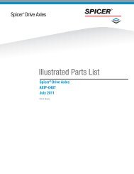
Medium-Duty CTD <strong>with</strong> Optional<br />
Fork for Seasonal or Driver-<br />
Controlled Engagement.<br />
Heavy-Duty CTD <strong>with</strong> Optional<br />
Fork for Seasonal or Driver-<br />
Controlled Engagement.<br />
Checking Effectiveness of Controlled Traction Differentials<br />
(to determine friction plate condition)<br />
The bias torque of a new unit will Check bias torque values as follows: d. Using a torque wrench, rotate<br />
check out at approximately 4,000<br />
pinion <strong>and</strong> note torque reading.<br />
a. Disconnect drive shaft at drive<br />
ft-lbs. (or higher) for Heavy-duty pinion.<br />
e. Formula: Torque times axle ratio<br />
CTD, 3,000 ft-lbs. (or higher) for<br />
Medium-duty CTD. If bias torque b. Block one wheel or otherwise<br />
equals bias differential torque.<br />
value drops to 1,500 ft-lbs. (or less), restrain vehicle.<br />
replace the clutch pack.<br />
c. Jack up other wheel free of the<br />
ground.<br />
AS ADDITIONAL SUPPORT OF<br />
VEHICLE TO PREVENT PER-<br />
SONAL INJURY OR VEHICLE<br />
DAMAGE.
Lubrication<br />
Clutch Pack Lubrication<br />
<strong>Axle</strong> lube provides lubrication for<br />
the clutch pack through a unique<br />
system of distribution channels.<br />
The diagram (to the right) illustrates<br />
how the lube is forced<br />
through the wheel differential<br />
<strong>and</strong> clutch pack.<br />
Controlled Traction<br />
Differential Lube System<br />
Driver-Controlled CTD Shift Unit<br />
The driver-controlled type traction<br />
differential is usually engaged <strong>and</strong><br />
disengaged by an air-type shift unit,<br />
operated from the vehicle cab.<br />
Shift units are activated by air.<br />
For details, see Shift System<br />
Section of this manual.<br />
Typical Air Shift Unit<br />
for Driver-Controlled<br />
Traction Differential<br />
Shift Unit Lubrication<br />
Use SAE 10 motor oil for temperatures<br />
above 0 o F (-18 o C). For temperatures<br />
below 0 o F (-18 o C), mix<br />
three parts of SAE 10 motor oil<br />
<strong>with</strong> one part of kerosene. This cold<br />
weather mixture can be safely used<br />
up to 32 o F (O o C).<br />
NOTE: Commercially available<br />
automatic transmission fluid may<br />
be used in place of SAE 10 motor<br />
oil. Automatic transmission fluid<br />
can be used for all temperatures.<br />
Do not mix kerosene <strong>with</strong> automatic<br />
transmission fluid.<br />
Lubricant Check <strong>and</strong> Level<br />
Each 20,000 miles or 6 months,<br />
remove pipe plug in shift unit<br />
housing cover to check lubricant<br />
level. Oil should be level <strong>with</strong><br />
bottom of filler hole.<br />
Lubricant Change<br />
At least once a year, remove shift<br />
unit housing cover <strong>and</strong> drain old<br />
lubricant. Wash parts thoroughly<br />
<strong>and</strong> air dry. Reinstall cover.<br />
Remove pipe plug in cover. Fill<br />
through pipe plug opening until<br />
lubricant is level <strong>with</strong> bottom of<br />
filler hole.<br />
Air-Shift<br />
Unit Oil<br />
Filler Hole<br />
5
Adjustments<br />
CTD Adjustments<br />
No specific adjustments are required for the controlled traction differential unit itself. If clutch plates are worn<br />
excessively, replace clutch pack.<br />
Shifting Seasonal C T D<br />
Provisions are made for engaging<br />
or disengaging this type CTD <strong>with</strong><br />
a simple manual shop adjustment.<br />
Procedure for Engaging <strong>and</strong><br />
Disengaging Seasonal CTD<br />
Engaging — To engage, remove the shift fork cover<br />
retainer. Push the protruding end of the shift fork<br />
away from the carrier. If the shift fork will not move,<br />
lift both wheels off the ground (leave vehicle transmission<br />
in gear <strong>and</strong> release parking brake). While<br />
pushing on the shift fork, rotate the wheel on the<br />
shift fork side of the carrier very slowly. The shift<br />
fork should now be in the engaged position.<br />
To reassemble cover retainer, the adjusting screw<br />
must be backed out several turns. This is done so<br />
that the shift fork cover retainer bolt holes align <strong>with</strong><br />
the studs on the carrier. Once the shift fork cover<br />
retainer is in place (adjusting screw facing carrier),<br />
tighten the shift fork cover retainer nuts to the specified<br />
torque (see chart). Now turn the adjusting screw<br />
in until it contacts the shift fork. While holding the<br />
adjusting screw <strong>with</strong> a wrench, tighten the locknut<br />
to the torque specified (see chart).<br />
Disengaging — To disengage, remove the shift fork<br />
cover retainer. Push the protruding end of the shift<br />
fork toward the carrier. If the shift fork will not move,<br />
lift both wheels off the ground (leave vehicle transmission<br />
in gear <strong>and</strong> release parking brake), then<br />
push on the shift fork. The shift fork should now<br />
move to the disengaged position.<br />
To reassemble, place the shift fork cover retainer on<br />
the carrier so that the adjusting screw is facing away<br />
from the carrier. The adjusting screw may need to<br />
be backed out of the shift fork cover retainer several<br />
turns so that the shift fork cover bolt holes align <strong>with</strong><br />
the studs on the carrier. Once the shift fork cover is<br />
in place, tighten the shift fork cover nuts to the specified<br />
torque (see chart). Now turn the adjusting screw<br />
in until it contacts the shift fork. while holding the<br />
adjusting screw <strong>with</strong> a wrench tighten the locknut<br />
to the torque specified (see chart).<br />
Fastener Tightening Specifications<br />
Size Ft-lbs. N.m<br />
Ring Gear to Support Case<br />
Bolt/Nut . . . . . . . . . . . . . . . . . . . . . . . . . . . 3/4-16 (Grade 8) 275-300 373-407<br />
5/8-18 (Grade 8) 195-245 264-332<br />
Shift Unit Stud/Nut . . . . . . . . . . . . . . . . . 7/16-20 (Grade 8) 55-61 74-82<br />
Shift Fork Cover Cap Screw . . . . . . . . . 7/16-14 (Grade 5) 35-45 47-61<br />
(Permanent CTD only)<br />
Shift Fork Cover Retainer Stud/Nut . . . 7/16-20 (Grade 8) 55-61 74-82<br />
(Seasonal CTD only)<br />
Adjusting Screw Locknut . . . . . . . . . . . . 1/2-20 30-40 41-54<br />
(Seasonal CTD only)<br />
Other <strong>Axle</strong> Parts . . . . . . . . . . . . . . . . . . . .<br />
Refer to appropriate Spicer <strong>Service</strong> <strong>Manual</strong> (See back cover).<br />
6
CTD Overhaul (All Type.)<br />
Remove Differential Carrier Assembly from <strong>Axle</strong> Housing<br />
IMPORTANT: Detailed procedures for each type, capacity or<br />
model axle may vary. For specific service instructions on your<br />
axle, refer to the appropriate Spicer <strong>Service</strong> <strong>Manual</strong>. The following<br />
instructions are applicable to axles equipped <strong>with</strong> Controlled<br />
Traction Differentials.<br />
1. Driver-Controlled CTD: Remove 2. Seasonal CTD Remove nuts<br />
shift unit nuts <strong>and</strong> flat washers. Dis- <strong>and</strong> washers from shift fork cover<br />
connect air line to permit removal retainer, then remove cover retainer.<br />
of shift unit. Place sliding clutch Place sliding clutch in the engaged<br />
in the engaged position. (Sliding position. (Sliding clutch must be<br />
clutch must be engaged to allow engaged to allow removal of carrier<br />
removal of carrier from housing. ) from housing.)<br />
3. Permanent CTD: This type CTD<br />
is always engaged. No procedure<br />
is necessary.<br />
4. All Types CTD: Drain lubricant.<br />
Disconnect drive shaft <strong>and</strong> remove<br />
axle shafts. Remove differential<br />
carrier to axle housing cap screws<br />
<strong>and</strong> lockwashers or stud nuts.<br />
Remove differential carrier.<br />
Remove Differential <strong>and</strong> Clutch Pack Assembly from Carrier<br />
NOTE: If the gear set is to be<br />
reused, check tooth contact pattern<br />
<strong>and</strong> ring gear backlash before<br />
beginning disassembly. Best overhaul<br />
results are obtained when<br />
used gearing is adjusted to run<br />
in established wear patterns. Omit<br />
this step if the gear set is to be<br />
replaced.<br />
When reusing the gear set, remove<br />
the left-h<strong>and</strong> bearing cap, adjuster<br />
<strong>and</strong> lock as a unit. This will help<br />
return the gear set to its original<br />
adjustment during reassembly.<br />
Removing Shift Fork Shaft<br />
Removing Sliding Clutch<br />
1. Mount the differential carrier in<br />
a repair st<strong>and</strong>.<br />
2. Driver-Controlled <strong>and</strong> Seasonal<br />
CTD Only: Remove shift fork seal<br />
<strong>and</strong> spring. Remove expansion<br />
plugs, then working at the lower<br />
(or small) plug hole, drive out the<br />
shift fork shaft.<br />
WARNING: WHEN USING A<br />
DRIFT, PUNCH OR SIMILAR<br />
TOOL, WEAR SAFETY GLASSES.<br />
3. Driver-Controlled <strong>and</strong> Seasonal<br />
CTD Only: Disengage shift fork<br />
yoke from sliding collar. Then<br />
remove clutch <strong>and</strong> shift fork.<br />
7
CTD Overhaul (All Types)<br />
Remove Differential <strong>and</strong> Clutch Pack Assembly from Carrier (Cont'd)<br />
4. If reusing gear set, punch mark<br />
bearing adjusters for reference<br />
during assembly.<br />
5. On teeth-side of ring gear, cut<br />
lockwire <strong>and</strong> remove bearing cap<br />
screws. Remove cap, adjuster <strong>and</strong><br />
lock.<br />
6. On back-side of ring gear, cut<br />
lockwire <strong>and</strong> remove bearing cap<br />
screws. If the gear set is to be<br />
reused, remove bearing cap,<br />
adjuster <strong>and</strong> lock as an assembly.<br />
This will facilitate correct positioning<br />
of ring gear during reassembly.<br />
7. Remove bearing cups, then lift<br />
ring gear <strong>and</strong> differential assembly<br />
out of carrier.<br />
Remove Drive Pinion<br />
1. For pinion instructions, refer<br />
to appropriate Spicer <strong>Axle</strong><br />
<strong>Service</strong> <strong>Manual</strong> covering your<br />
specific axle model. (see back<br />
cover)<br />
8
CTD Overhaul (Medium-duty Type)<br />
Remove <strong>and</strong> Disassemble Clutch Pack<br />
1. Place differential assembly 2. Remove two self-locking nuts<br />
(clutch pack up) on workbench. <strong>and</strong> bolts (180 o apart) fastening<br />
WARNING: TAKE PRECAUTION- support case cover, then temporarily<br />
install two clamping bolts <strong>and</strong><br />
ARY MEASURES TO PREVENT<br />
PERSONAL INJURY OR PARTS nuts (see photo).<br />
DAMAGE DURING REMOVAL OF NOTE: These clamping bolts will<br />
GEAR SUPPORT COVER (Step 2) hold cover in position while removing<br />
the other cover self-locking<br />
THE COVER IS UNDER SPRING<br />
PRESSURE AND MAY POP OFF bolts <strong>and</strong> nuts.<br />
WHEN THE LAST LOCKNUT IS Remove cover self-locking bolts<br />
REMOVED.<br />
<strong>and</strong> nuts.<br />
Removing Case Cover<br />
(<strong>with</strong> clamping nuts<br />
<strong>and</strong> bolts installed)<br />
9
CTD Overhaul (Medium-duty Type)<br />
Remove <strong>and</strong> Disassemble Clutch Pack (ContÍd)<br />
3. With cover self-locking bolts<br />
<strong>and</strong> nuts removed, alternately<br />
loosen <strong>and</strong> remove the two clamping<br />
nuts <strong>and</strong> bolts.<br />
Removing Clamping Nuts <strong>and</strong><br />
Bolts<br />
4. Lift off cover <strong>and</strong> remove springs.<br />
Removing Support Case Cover<br />
5. Driver-Controlled <strong>and</strong> Seasonal<br />
CTDs Only: With cover <strong>and</strong> springs<br />
removed, the pressure plate <strong>and</strong><br />
clutch pack (friction plates) can be<br />
<strong>with</strong>drawn or lifted out of ring gear<br />
bore. If difficulty is experienced,<br />
first remove pressure plate then lift<br />
out friction plates individually.<br />
6. Permanent CTDs Only: This<br />
type unit includes a driver to engage<br />
internal-splined friction plates<br />
to the differential side gear. With<br />
cover <strong>and</strong> springs removed, the<br />
pressure plate, clutch plate <strong>and</strong><br />
driver can be <strong>with</strong>drawn or lifted<br />
out of the ring gear bore. The individual<br />
parts can then be separated.<br />
The snap ring on the friction plate<br />
driver acts as a stop for the plates.<br />
Remove snap ring if replacement<br />
is necessary.<br />
Removing Clutch Pack<br />
7. If necessary, the ring gear can<br />
be removed from its mounting on<br />
the differential <strong>and</strong> gear support<br />
case (flanged case half). If difficulty<br />
is encountered, loosen gear by tapping<br />
on opposite sides <strong>with</strong> a softnosed<br />
hammer.<br />
8. If necessary, remove bearing<br />
cone from support case cover using<br />
suitable puller.<br />
NOTE: Holes are provided in the<br />
cover to enable removal of bearing<br />
cone <strong>with</strong> a punch. Tap alternately<br />
through each hole until cone is<br />
removed.<br />
9. Inspect Friction Plates. With<br />
plates removed, inspect surfaces<br />
for deeply scored or burned condition.<br />
If a faulty condition is found<br />
or if torque check indicates a worn<br />
condition (see "Checking Effectiveness<br />
of the Controlled Traction<br />
Differential," page 4), replace<br />
t h e c l u t c h pac k :<br />
1. For procedure, refer to the<br />
appropriate Spicer <strong>Axle</strong> <strong>Service</strong><br />
<strong>Manual</strong> covering your specific axle<br />
model (see back cover).<br />
10
Assemble <strong>and</strong> Install Clutch Pack<br />
NOTE: The clutch pack can be installed in differential <strong>and</strong> gear support<br />
case <strong>with</strong> wheel differential assembled or disassembled. With differential<br />
assembled, proceed as follows:<br />
1. All Medium-duty CTD. Place differential<br />
assembly on a work bench<br />
(clutch pack mounting area up).<br />
Install ring gear on support case<br />
flange, aligning bolt holes <strong>with</strong> two<br />
temporarily-installed alignment<br />
bolts.<br />
Remove alignment bolts.<br />
2. Install Friction Plates <strong>and</strong> Driver<br />
(Permanent CTD Only).<br />
NOTE: Brush surface of each plate,<br />
as it is assembled, <strong>with</strong> heavy application<br />
of axle lube (SAE 90).<br />
NOTE: To assemble friction plates,<br />
one of two procedures can be used:<br />
Install driver <strong>and</strong> plates individually<br />
(Step 3) or install driver <strong>and</strong> clutch<br />
pack as an assembly (Step 4).<br />
Installing Clutch Plates Individually<br />
(Permanent CTD Only)<br />
3. Install Friction Plates Individually<br />
(Permanent CTD Only).<br />
a. If removed, install snap ring on<br />
friction plate driver. Then, install<br />
driver assembly (snap ring down)<br />
in bore of support case, engaging<br />
teeth of differential side gear.<br />
b. Place one external-splined plate<br />
in ring gear bore (engaging gear<br />
internal teeth). Brush plate <strong>with</strong><br />
lube.<br />
c. Place one internal-splined plate<br />
on driver splines <strong>and</strong> on top of the<br />
external-splined plate. Brush plate<br />
<strong>with</strong> lube.<br />
d. Repeat this procedure until<br />
fourteen (14) friction plates (seven<br />
internal-splined <strong>and</strong> seven externalsplned)<br />
are installed.<br />
e. Install the last external-splined<br />
plate <strong>and</strong> pressure plate. Then install<br />
springs <strong>and</strong> cover (see Step 6).<br />
installing Clutch Pack <strong>and</strong> Driver<br />
Assembly (Permanent CTD Only)<br />
4. Install Driver <strong>and</strong> Clutch Pack<br />
as an Assembly (Permanent CTD<br />
Only).<br />
a. If removed, install snap ring<br />
on friction plate driver. Then, place<br />
driver (snap ring down) on work<br />
bench.<br />
b. Place one external-splined plate<br />
on driver. Brush plate <strong>with</strong> lube.<br />
c. Place one internal-splined plate<br />
on top of the external-splined plate.<br />
Brush plate <strong>with</strong> lube.<br />
d. Repeat this procedure until<br />
fourteen (14) friction plates (seven<br />
external-splined <strong>and</strong> seven internalsplined)<br />
are installed. Then install<br />
the last external-splined plate <strong>and</strong><br />
pressure plate.<br />
e. Rotate external-splined plates as<br />
necessary to align the teeth. Then<br />
grasp the entire assembly by h<strong>and</strong><br />
(see photo) <strong>and</strong> install it in the<br />
ring gear.<br />
NOTE: As the assembly is installed,<br />
maneuver plates <strong>with</strong> external<br />
splines to align them <strong>with</strong> the ring<br />
gear teeth. Also make sure the<br />
driver engages teeth of the differential<br />
side gear.<br />
f. Install compression springs<br />
<strong>and</strong> case cover (Step 6).<br />
11
I<br />
CTD Overhaul (Medium-duty Type<br />
Assemble <strong>and</strong> Install Clutch Pack (Cont'd)<br />
5. Install Friction Plates (Driver-Controlled <strong>and</strong> Seasonal CTD Only).<br />
NOTE: During friction plate (internal-splines) installation, align each<br />
plate as it is installed in ring gear, using the sliding clutch. If plates are<br />
not in alignment, it will be difficult to install sliding clutch, after clutch<br />
pack is assembled. Also, as each plate is installed, brush top of plate<br />
<strong>with</strong> a heavy application of axle lube (SAE 90). Proceed as follows:<br />
a. Place one external-splined plate<br />
in ring gear bore (engaging gear<br />
internal teeth). Brush plate <strong>with</strong><br />
lube.<br />
b. Place one internal-splined plate<br />
on top of the external-splined plate<br />
<strong>and</strong> brush plate <strong>with</strong> lube. For<br />
alignment purposes, temporarily<br />
insert sliding clutch to engage<br />
side gear <strong>and</strong> plate splines.<br />
Remove clutch.<br />
c. Repeat this procedure until<br />
fourteen (14) friction plates (seven<br />
Installing External-Splined Friction<br />
internal-splined <strong>and</strong> seven external-<br />
Plate<br />
splined) are installed.<br />
d. Install the last external-splined<br />
plate <strong>and</strong> the pressure plate. And,<br />
again, insert sliding clutch to make<br />
sure internal-splined plates are in<br />
alignment. Install springs <strong>and</strong> case<br />
cover (see Step 6).<br />
AIigning internal-Splined Friction<br />
Plate <strong>with</strong> Sliding Clutch<br />
6. Install Compression Springs <strong>and</strong> Cover (All Types CTD).<br />
a. Install springs on pressure plate,<br />
positioning them in the smallest<br />
circle possible (see photo).<br />
b. Place support case cover over springs <strong>and</strong> temporarily install two<br />
alignment bolts (heads up).<br />
c. Temporarily, install two clamping<br />
nuts <strong>and</strong> bolts (nuts up). Remove<br />
alignment bolts. Alternately, tighten<br />
clamping nuts until cover is in<br />
mounting position on ring gear.<br />
d. Install bolts <strong>and</strong> self-locking<br />
nuts that fasten cover to ring gear.<br />
Remove the temporarily-installed<br />
clamping nuts <strong>and</strong> bolts <strong>and</strong> install<br />
the remaining cover bolts <strong>and</strong> self-<br />
Iocking nuts. Torque nuts to<br />
275-300 ft-lbs. (373-407 N.m).<br />
12
CTD Overhaul (Heavy-duty Type)<br />
Remove <strong>and</strong> Disassemble Clutch Pack<br />
1. Place differential <strong>and</strong> gear<br />
support case (clutch pack up) on<br />
workbench.<br />
WARNING: EXERCISE CARE<br />
DURING DISASSEMBLY PROCE-<br />
DURE (Step 2 below). THE GEAR<br />
SUPPORT CASE COVER IS<br />
UNDER SPRING PRESSURE AND<br />
THE RING GEAR MAY FALL OFF<br />
THE SUPPORT CASE AFTER THE<br />
LAST LOCKNUT IS REMOVED.<br />
TAKE PRECAUTIONARY<br />
MEASURES TO PREVENT PER-<br />
SONAL INJURY OR PARTS<br />
DAMAGE DURING PROCEDURE<br />
IN STEP 2, BELOW.<br />
2. Remove self-locking nuts <strong>and</strong><br />
bolts, then lift off gear support case<br />
cover <strong>and</strong> compression springs.<br />
Removing Gear Support Case Cover<br />
13
CTD Overhaul (Heavy-duty Type)<br />
Remove <strong>and</strong> Disassemble Clutch Pack (ContÍd)<br />
(Heavy-duty Type)<br />
Removing Clutch Pack<br />
3. Lift up <strong>and</strong> remove clutch pack<br />
assembly from the differential <strong>and</strong><br />
gear support case (see photo),<br />
4. If ring gear had an interference<br />
fit <strong>and</strong> did not fall off as previously<br />
mentioned in the warning note for<br />
Step 2, tap ring gear alternately<br />
on opposite sides <strong>with</strong> soft-nosed<br />
hammer until ring gear is free of<br />
gear support case flange.<br />
Compressing Clutch Pack in a<br />
Press (<strong>with</strong> clutch pack installed<br />
in support case)<br />
5. Disassemble Clutch Pack. To<br />
disassemble clutch pack, use a<br />
press <strong>and</strong> suitable adapters.<br />
NOTE: This procedure can be<br />
accomplished <strong>with</strong> clutch pack<br />
removed from or installed in support<br />
case (see photo).<br />
Compress clutch pack, then remove<br />
"round" snap ring. Remove pressure<br />
plate, then alternately remove<br />
tanged <strong>and</strong> splined friction plates<br />
from friction plate driver.<br />
Removing Tanged <strong>and</strong> Splined<br />
Friction Plates<br />
6. If necessary, remove "rectangular"<br />
snap ring from friction plate<br />
driver.<br />
7. If necessary to remove bearing<br />
cone from differential case cover,<br />
place pilot punch in holes provided<br />
<strong>and</strong> tap on bearing cone inner race<br />
alternately through each hole until<br />
cone is removed.<br />
8. Inspect Friction Plates. With plates removed, inspect surfaces for<br />
deeply scored or burned condition. If a faulty condition is found or if<br />
torque check indicates a worn condition (see "Checking Effectiveness<br />
of the Controlled Traction Differential," page 4), replace the clutch<br />
pack.<br />
Disassemble <strong>and</strong> Reassemble Wheel Differential<br />
1. For procedure, refer to the<br />
appropriate Spicer <strong>Axle</strong> <strong>Service</strong><br />
<strong>Manual</strong> covering your specific<br />
axle model (see back cover).<br />
.<br />
14
Assemble <strong>and</strong> Install Clutch Pack<br />
NOTE: The clutch pack can be installed in gear support case <strong>with</strong><br />
wheel differential assembled or disassembled. With differential<br />
assembled, proceed as follows:<br />
NOTE: Ring gear may fit loosely or have an interference fit on the gear<br />
support case. Proceed as necessary to assemble ring gear to support<br />
case (Step 1 or 2).<br />
1. Install Ring Gear <strong>with</strong> interference<br />
Fit. Place gear support case<br />
assembly on bench <strong>with</strong> clutch<br />
pack side down. Position ring gear<br />
(gear teeth up) on gear support<br />
case <strong>and</strong> align bolt holes. Temporarily,<br />
install two ring gear bolts<br />
to assure alignment, then tap ring<br />
gear alternately on opposite sides<br />
<strong>with</strong> a soft-nosed hammer until<br />
gear is fully seated against gear<br />
support case flange. Turn assembly<br />
over, then place in press (gear teeth<br />
down) on hard wood blocks. Position<br />
blocks to the outside of the<br />
ring gear to allow clearance for<br />
installation of two alignment bolts.<br />
Install alignment bolts, then proceed<br />
<strong>with</strong> reassembly procedures<br />
in Step 3.<br />
2. Install Ring Gear <strong>with</strong> Loose Fit.<br />
Place ring gear in press (gear teeth<br />
down) on hard wood blocks. Position<br />
blocks to the outside of the<br />
ring gear to allow clearance for<br />
installation of the gear support case<br />
assembly <strong>and</strong> two alignment bolts.<br />
Place gear support case assembly<br />
in ring gear <strong>and</strong> align bolt holes.<br />
Install two alignment bolts in<br />
mounting holes, then proceed <strong>with</strong><br />
reassembly procedures in Step 3.<br />
Installing Friction Plate Driver<br />
3. Install snap ring in square ring<br />
groove of friction plate driver. Place<br />
friction plate driver (<strong>with</strong> snap ring<br />
down) in center of gear support<br />
case.<br />
4. Place one tanged friction plate<br />
over friction plate driver, positioning<br />
tangs into slots in gear support<br />
case (see photo). Brush top of friction<br />
plate <strong>with</strong> a heavy application<br />
of axle lube (SAE 90). Place one<br />
splined friction plate over friction<br />
plate driver <strong>and</strong> brush top of this<br />
plate <strong>with</strong> lube.<br />
5. Repeat procedures in Step 4<br />
until there are an equal amount of<br />
friction plates of each (tanged <strong>and</strong><br />
splined) mounted on the friction<br />
plate driver (see note below).<br />
NOTE: Clutch pack friction plates<br />
vary <strong>with</strong> axle models (see chart<br />
on page 2 for detailed information).<br />
Installing Friction Plates<br />
15
CTD Overhaul (Heavy-duty Type)<br />
Assemble <strong>and</strong> Install Clutch Pack (ContÕd)<br />
(Heavy-duty CTD)<br />
6. Place last tanged friction plate<br />
<strong>and</strong> pressure plate over friction<br />
plate driver. Then using a press<br />
<strong>and</strong> suitable adapters, compress<br />
clutch pack <strong>and</strong> install round snap<br />
ring in groove of friction plate<br />
driver.<br />
7. If removed, press bearing cone<br />
on gear support case cover.<br />
Compressing Clutch Pack<br />
in a Press<br />
Positioning Compression Springs on Pressure<br />
Plate<br />
8. Place compression springs in<br />
smallest possible circle on pressure<br />
plate. Place gear support case<br />
cover over springs <strong>and</strong> temporarily<br />
install two alignment bolts. Reach<br />
through hole in gear support case<br />
cover <strong>and</strong> move compression<br />
springs radially outward as far<br />
as they will go.<br />
Compressing Springs to Assemble Ring Gear,<br />
Case <strong>and</strong> Cover<br />
9. Compress springs until gear<br />
case cover bottoms against gear<br />
support case. With press pressure<br />
still applied, install ring gear bolts<br />
(all bolt heads on ring gear side)<br />
<strong>and</strong> locknuts. Remove assembly<br />
from press, then tighten locknuts<br />
to correct torque (195-245 ft-lbs.,<br />
264-332 N.m).<br />
16
CTD Overhaul (All Types)<br />
Install Drive Pinion<br />
NOTE: If the drive pinion was removed, refer to the appropriate<br />
Spicer <strong>Service</strong> <strong>Manual</strong> covering your specific axle for instructions.<br />
Install Differential <strong>and</strong> Clutch Pack Assembly in Carrier (All Types CTD) Ñ<br />
NOTE: Lubricate bearings during<br />
the following assembly procedure:<br />
1. Place ring gear <strong>and</strong> differential<br />
assembly in carrier Insure that<br />
ring gear <strong>and</strong> drive pinion mesh<br />
properly.<br />
During installation, tilt carrier to<br />
allow support case pilot to rest in<br />
carrier bore, then install bearing<br />
cup as shown in photo. Also<br />
install bearing cup on opposite<br />
side of differential<br />
2. If the same gear set is used,<br />
install the assembled bearing cap,<br />
adjuster <strong>and</strong> lock on the backface<br />
side of the ring gear. Otherwise<br />
install adjuster <strong>and</strong> cap separately.<br />
NOTE: When installing cap, it may<br />
be necessary to tap it lightly <strong>with</strong> a<br />
hammer. Be sure cap is fully<br />
seated <strong>and</strong> threads are aligned<br />
properly. If trouble is encountered,<br />
check for cross-threading of bearing<br />
adjuster <strong>and</strong> carrier threads.<br />
On teeth side of ring gear, install<br />
the other adjuster <strong>and</strong> bearing<br />
cap, observing same precautions<br />
to avoid cross-threading.<br />
3. Install <strong>and</strong> tighten bearing cap<br />
screws finger-tight. If this is difficult,<br />
use h<strong>and</strong> wrench.<br />
NOTE: The assembly is now ready<br />
for adjustment of differential bearing<br />
preload, ring gear backlash<br />
<strong>and</strong> gear tooth contact.<br />
17
CTD Overhaul (All Types)<br />
Adjust Differential Bearing Preload:<br />
1. At the teeth-side of ring gear, position bearing adjuster until its first<br />
thread is visible.<br />
2. At the back-face side of ring gear, tighten adjuster until there is no<br />
backlash.<br />
3. At the teeth-side of ring gear, tighten adjuster until it contacts the<br />
bearing cup. Continue tightening adjuster two or three notches. This<br />
will preload bearings <strong>and</strong> provide backlash.<br />
4. Check Ring Gear Backlash. Measure backlash <strong>with</strong> a dial indicator.<br />
Specifications are listed below.<br />
Ring Gear Backlash Specifications<br />
USED GEARING - Reset to backlash recorded before disassembly.<br />
NEW GEARING - Backlash should be as follows:<br />
<strong>Axle</strong>s <strong>with</strong> 16 1/2" (419.10 mm) or smaller<br />
ring gear diameter . . . . . . . . . . . . . . . . . . . . . . . . . . . . ..0.006" to 0.016"<br />
(0.152 to 0.406 mm)<br />
<strong>Axle</strong>s <strong>with</strong> 18" (457.20 mm) ring gears . . . . . . . . . . . ...0.008" to 0.018"<br />
(0.203 to 0.457 mm)<br />
5. Check Ring Gear Tooth Contact. Paint ring gear teeth <strong>and</strong> check<br />
tooth contact pattern. Correct tooth patterns are illustrated below.<br />
NOTE: For detailed instructions on checking <strong>and</strong> adjusting procedures,<br />
refer to the appropriate Spicer service manual covering your specific axle.<br />
Adjusting Bearing Adjuster<br />
Checking Ring Gear Backlash<br />
6. With ring gear <strong>and</strong> pinion adjusted correctly, align<br />
adjusters <strong>and</strong> locks, then tighten differential bearing<br />
cap screws to correct torque. Install cotter pin in one<br />
adjuster lock. Install cap screws in opposite adjuster<br />
lock <strong>and</strong> tighten to correct torque. Lockwire bearing<br />
<strong>and</strong> adjuster lock cap screws.<br />
7. Seasonal <strong>and</strong> Driver-Controlled CTD Only: Position<br />
shift fork in carrier opening, then install-sliding<br />
clutch. With clutch installed, engage shift fork yoke<br />
<strong>with</strong> clutch collar. Then install shift fork shaft. Install<br />
expansion plugs to seal openings. Install shift fork<br />
seal <strong>and</strong> spring over end of shift fork. Move shift fork<br />
to place sliding clutch in engaged position. (Sliding<br />
clutch must be engaged to allow installation of carrier<br />
on housing. )<br />
18
Install Differential Carrier Assembly in <strong>Axle</strong> Housing (All Types)<br />
IMPORTANT: The following instructions cover single drive axles <strong>and</strong><br />
t<strong>and</strong>em rear axles. For t<strong>and</strong>em forward axles (cliff. <strong>with</strong> power divider),<br />
refer to the appropriate Spicer <strong>Axle</strong> <strong>Service</strong> <strong>Manual</strong>.<br />
IMPORTANT: Before installing carrier assembly, inspect <strong>and</strong> thoroughly<br />
clean interior of axle housing.<br />
NOTE: Use silicone rubber gasket compound on axle housing mating<br />
surface as shown in the illustration. Compound will set in 20 minutes.<br />
Install carrier before compound sets or reapply.<br />
1. Install differential carrier assembly in axle housing. Install stud nuts<br />
<strong>and</strong> lockwashers, tighten to correct torque.<br />
2. Install axle shafts <strong>and</strong> stud nuts. (If used, also install lockwashers <strong>and</strong><br />
taper dowels.)<br />
3. Connect driveline.<br />
4. Fill axle <strong>with</strong> correct lube to correct level.<br />
5. Driver-Controlled CTD: Install shift unit on carrier, engaging swivel<br />
<strong>with</strong> slot in shift fork shaft. Install mounting nuts <strong>and</strong> flat washers.<br />
Torque nuts (see chart). Connect air line to unit.<br />
6. Seasonal CTD: Position sliding clutch in the engaged or disengaged<br />
position, then install shift fork cover retainer <strong>and</strong> secure <strong>with</strong> self-<br />
Iocking nuts <strong>and</strong> washers. Torque nuts (see chart).<br />
NOTE: Shift fork cover retainer can be installed in two different positions;<br />
one to keep the sliding clutch engaged <strong>and</strong> the other to keep<br />
it disengaged. In the engaged position the shift fork cover retainer will<br />
have the adjusting screw facing the carrier, <strong>and</strong> away from the carrier in<br />
the disengaged position. Refer to page 6 for adjusting procedure.<br />
Silicone Gasket Compound<br />
Pattern Differential Carrier<br />
Mating Surface.<br />
Torque Chart<br />
Ft-lbs.<br />
Shift Unit<br />
STUD/NUT<br />
7/16-20 55-61<br />
(Grade 8)<br />
Shift Fork Cover<br />
(Permanent CTD only)<br />
CAP SCREW<br />
7/16-14 35-45<br />
(Grade 5)<br />
Shift Fork Cover Retainer<br />
(Seasonal CTD only)<br />
STUD/NUT<br />
7/16-20 55-61<br />
(Grade 8)<br />
Adjusting Screw<br />
(Seasonal CTD only)<br />
LOCKNUT<br />
1/2-20 30-40<br />
N.m<br />
74-82<br />
47-61<br />
74-82<br />
41-54<br />
Functional CTD Check (After Repair or Overhaul) (<strong>Single</strong> Or T<strong>and</strong>em <strong>Axle</strong>s)<br />
NOTE: This is an operational<br />
check during or after servicing all<br />
single <strong>and</strong> t<strong>and</strong>em CTD equipped<br />
axles.<br />
The following procedure can be<br />
used to determine whether the<br />
CTD is shifting in <strong>and</strong> out of the<br />
engaged mode. This functional<br />
check should be performed at any<br />
time the shift system components<br />
or axle CTD components are<br />
repaired or replaced.<br />
1. Block the vehicle wheels to prevent<br />
rolling.<br />
2. Place transmission in neutral<br />
<strong>and</strong> release parking brake.<br />
3. Jack up both rear wheels of the<br />
drive axle.<br />
4. With CTD selector valve in the<br />
disengaged position, the wheels<br />
will roll independent of one<br />
another.<br />
5. With the CTD selector valve<br />
moved to the engaged position, the<br />
wheels will not turn independent<br />
of one another.<br />
6. If the wheels turn independently<br />
in Step 5, the CTD is not functioning.<br />
Proceed to check for full system<br />
air pressure at shift unit.<br />
NOTE: The unit operates at full<br />
reservoir pressure.<br />
7. Remove shift unit <strong>and</strong> check to<br />
see if the shift unit pin <strong>and</strong> block<br />
were properly positioned into the<br />
shift fork opening.<br />
NOTE: It is possible to install the<br />
shift unit <strong>and</strong> miss the fork opening.<br />
If this occurs, the CTD will be<br />
locked in either the engaged or disengaged<br />
position <strong>and</strong> will not shift.<br />
If this situation is found, reinstall<br />
the unit while carefully aligning pin<br />
into fork. Then repeat Steps 5 <strong>and</strong><br />
6 to verify proper function.<br />
8. If shift unit installation <strong>and</strong> alignment<br />
was correct in Step 7, check<br />
the unit itself for proper functioning.<br />
With the shift unit removed,<br />
check it for proper travel by cycling<br />
the CTD selector valve. Travel<br />
should be 15/16” (23.8 mm). With<br />
pin in each position, pry <strong>with</strong> a<br />
screwdriver against the pin. This<br />
pin should not move when applying<br />
moderate force.<br />
9. if all of the above checks are<br />
made <strong>and</strong> found satisfactory, the<br />
failure of the CTD to properly<br />
engage involves internal axle parts.<br />
With the shift unit removed, the<br />
CTD can be shifted in <strong>and</strong> out of<br />
engagement manually. With the<br />
shift fork away from the carrier<br />
(engaged) the wheels should not<br />
rotate together.<br />
19
CTD Shift System (<strong>Single</strong> <strong>Axle</strong>)<br />
CTD Shift System (<strong>Single</strong> <strong>Axle</strong>s)<br />
Description <strong>and</strong> Operation<br />
This system provides the option of operating <strong>with</strong><br />
the Controlled Traction Differential engaged or<br />
disengaged <strong>with</strong> the use of an in-cab mounted<br />
pneumatic selector valve.<br />
Engagement. When the selector valve lever is moved<br />
to the engaged position, the selector valve is opened<br />
<strong>and</strong> air pressure is applied to the shift unit. The shift<br />
unit is connected to a shift fork <strong>and</strong> sliding clutch.<br />
The sliding clutch moves to engaged the Controlled<br />
Traction Differential. In the engaged position, the<br />
wheel differential acts a biasing differential.<br />
Disengagement. When the selector valve lever is<br />
moved to the disengaged position, the selector valve<br />
is closed. Air pressure in the shift unit is exhausted.<br />
The sliding clutch retracts <strong>and</strong> disengages the Controlled<br />
Traction Differential. In the disengaged position,<br />
the wheel differential functions <strong>with</strong> conventional<br />
differential action.<br />
. . .<br />
Troubleshooting (<strong>Single</strong> <strong>Axle</strong> Shift System)<br />
IMPORTANT: Before starting a<br />
system check, operate engine until<br />
full system air pressure (reservoir<br />
pressure) is built up in the system.<br />
CAUTION: HIGH AIR PRESSURE<br />
MAY BE PRESENT WHEN DIS-<br />
CONNECTING AIR LINES DUR-<br />
ING SYSTEM CHECK. EXERT<br />
CAUTION TO PREVENT POSSl-<br />
BLE PERSONAL INJURY.<br />
Check for Air Pressure <strong>and</strong> Air<br />
Leaks<br />
A simple method for quickly locating<br />
trouble in a shift system can be<br />
accomplished by listening for possible<br />
air leaks <strong>and</strong> for sound (or<br />
feel by h<strong>and</strong>) which would indicate<br />
mechanical shifting,<br />
Check Controlled Traction<br />
Differential System<br />
1. Start the system check by placing<br />
the controlled traction selector<br />
valve in the disengaged position.<br />
Release the parking brake <strong>and</strong><br />
place transmission in neutral.<br />
2. Lift the wheel on the shift unit<br />
side of the axle off the ground. Turn<br />
the wheel. Both the wheel <strong>and</strong> the<br />
drive shaft should rotate. If the<br />
wheel rotates, go to Step 6. If<br />
wheel will not rotate, proceed to<br />
the next step.<br />
3. Verify that there is no air pressure<br />
at the shift unit by disconnecting<br />
the air line. If air pressure at the<br />
shift unit is present, check for possible<br />
exhaust port blockage at the<br />
CTD selector valve. If no blockage<br />
is found, the CTD selector valve is<br />
defective <strong>and</strong> needs replacement.<br />
4. If there is no air pressure at the<br />
shift unit, remove the shift unit <strong>and</strong><br />
have an assistant move the CTD<br />
selector valve back <strong>and</strong> forth. The<br />
shift unit linkage should move<br />
accordingly. If linkage does not<br />
move, disassemble shift unit <strong>and</strong><br />
repair (see page 26). If the shift<br />
unit functions properly, proceed<br />
to Step 5.<br />
5. With the shift unit removed,<br />
move the protruding end of the<br />
shift fork from side to side. If shift<br />
fork will not move, the problem is<br />
in the carrier assembly. Remove<br />
carrier <strong>and</strong> inspect components.<br />
6. Have an assistant move the<br />
selector valve to the engaged position.<br />
Turn the wheel that is off the<br />
ground. Neither the wheel or the<br />
drive shaft should rotate. If the<br />
wheel rotates, proceed to next step.<br />
7. Verify that there is full system air<br />
pressure at the shift unit. If no air<br />
pressure is present, selector valve is<br />
defective <strong>and</strong> needs replacement.<br />
8. If there is air pressure at shift<br />
unit, remove the shift unit by first<br />
placing the selector valve in the<br />
disengaged position. Then have an<br />
assistant move the selector valve<br />
back <strong>and</strong> forth. The shift unit linkage<br />
should move accordingly. If<br />
linkage does not move, disassembly<br />
shift unit <strong>and</strong> repair (see page 26).<br />
If the shift unit functions properly,<br />
move the protruding end of the shift<br />
fork from side to side. If the shift<br />
fork will not move, remove differential<br />
carrier <strong>and</strong> check components.<br />
NOTE: For CTD Functional<br />
Check, see page 19.<br />
20
CTD Shift System <strong>Axle</strong>s)<br />
Description <strong>and</strong> Operation<br />
The CTD Shift System provides the option of operation <strong>with</strong> the Controlled Traction Differential engaged or<br />
disengaged <strong>with</strong> the use of an in-cab pneumatic valve.<br />
Two shift units (one on each axle) engage or disengage the Controlled Traction Differentials. A quick release<br />
valve in the system provides fast release of air pressure from the shift units.<br />
There are two types of CTD Shift Systems for t<strong>and</strong>em axles: (1) a One-Selector Valve System controlling<br />
operation of the Inter-<strong>Axle</strong> Differential <strong>and</strong> both Controlled Traction Differentials, or (2) a Two-Selector Valve<br />
System which offers independent control of the Inter-Ax/e Differential <strong>and</strong> the Controlled Traction Differentials.<br />
These systems are illustrated on the next page.<br />
Instruction in this manual are the same for both systems unless specified otherwise.<br />
Disengagement. When the selector valve lever is<br />
moved to the disengaged position, the selector valve<br />
is closed. Air pressure in the shift unit (or units) is<br />
exhausted. The sliding clutch retracts <strong>and</strong> disengag-<br />
es the Controlled Traction Differential. in the disen-<br />
gaged position, the wheel differential functions <strong>with</strong><br />
conventional differential action.<br />
Engagement. When the selector valve lever is moved<br />
to the engaged position, the selector valve is opened<br />
<strong>and</strong> air pressure is applied to the shift unit (or units).<br />
Each shift unit is connected to a shift fork <strong>and</strong> sliding<br />
clutch. The sliding clutch moves to engage the Controlled<br />
Traction Differential. In the engaged position,<br />
the wheel differential acts a biasing differential.<br />
in the One-Selector Valve System, both CTD wheel<br />
differentials <strong>and</strong> Inter-<strong>Axle</strong> Differential are disen-<br />
gaged when the selector valve is in the disengaged<br />
position.<br />
In the One-Selector Valve System, the CTD <strong>and</strong><br />
Inter-<strong>Axle</strong> Differential are controlled by one valve <strong>and</strong><br />
both are engaged when the selector valve is in the<br />
engaged position.<br />
In the Two-Selector Valve System, both CTD differ-<br />
entials <strong>and</strong> the Inter-<strong>Axle</strong> Differential are disengaged<br />
independently.<br />
In the Two-Selector Valve System, both CTD differentials<br />
<strong>and</strong> the Inter-<strong>Axle</strong> Differential are engaged<br />
independently.<br />
CTD Shift Unit. For detailed description <strong>and</strong> operation, refer to page 25.<br />
Inter-<strong>Axle</strong> Differential Lockout Shift Unit. For detailed description <strong>and</strong> operation, refer to the appropriate<br />
Spicer <strong>Axle</strong> <strong>Service</strong> <strong>Manual</strong> covering your axle model (see back cover).<br />
21
CTD Shift System (T<strong>and</strong>em <strong>Axle</strong>s)<br />
One-Selector Valve CTD Shift System<br />
In the One-Selector Valve System,<br />
all three differentials are engaged<br />
or disengaged by a single selector<br />
valve .<br />
Two-Selector Valve CTD Shift System<br />
The Two-Selector Va/ve System<br />
provides independent control of<br />
both CTD Differentials <strong>and</strong> Inter-<br />
<strong>Axle</strong> Differential Operation.<br />
22
Except where specified otherwise,<br />
the following instructions cover<br />
Controlled Traction Shift Systems<br />
<strong>with</strong> one or two selector valves.<br />
IMPORTANT: Before starting a<br />
system check, make sure the interaxle<br />
differential is disengaged.<br />
Also, operate engine until full<br />
system air pressure (reservoir<br />
pressure) is built up in the system.<br />
Check for Air Pressure <strong>and</strong> Air<br />
Leaks<br />
A simple method for quickly locating<br />
trouble in a shift system can be<br />
accomplished by listening for possible<br />
air leaks <strong>and</strong> for sound (or<br />
feel by h<strong>and</strong>) which would indicate<br />
mechanical shifting.<br />
Disengage Inter-<strong>Axle</strong> Differential<br />
(One-Selector Valve System)<br />
For vehicles equipped <strong>with</strong> a system<br />
that engages both CTD differentials<br />
when the inter-axle differential<br />
is engaged, the following<br />
steps must be taken to make sure<br />
the inter-axle differential is disengaged<br />
before checking the CTD<br />
shift system.<br />
1. Start the system check by releasing<br />
the parking brake <strong>and</strong> place<br />
transmission in neutral.<br />
2. Place the inter-axle differential<br />
selector valve in the disengaged<br />
position.<br />
3. Lift both wheels of the rear axle<br />
off the ground.<br />
4. Rotate the inter-axle drive shaft.<br />
If drive shaft turns, the inter-axle<br />
differential is disengaged. If it does<br />
not turn, the inter-axle differential<br />
shift mechanism is not functioning<br />
properly. Refer to appropriate<br />
Spicer <strong>Axle</strong> <strong>Service</strong> <strong>Manual</strong> for<br />
disassembly <strong>and</strong> repair.<br />
5. After confirming that the interaxle<br />
differential is disengaged, disconnect<br />
the air line connected to<br />
the inter-axle differential lockout<br />
shift unit <strong>and</strong> plug the end of the<br />
line.<br />
CAUTlON: HIGH PRESSURE<br />
MAY BE PRESENT WHEN DIS-<br />
CONNECTING AIR LINE. EXERT<br />
CAUTION TO PREVENT POSSl-<br />
BLE PERSONAL INJURY.<br />
Disengage Inter-<strong>Axle</strong> Differential<br />
(Two-Selector Valve System)<br />
For vehicles equipped <strong>with</strong> two<br />
selector valves, one for operating<br />
the inter-axle differential shift unit<br />
<strong>and</strong> the other for the CTD shift<br />
units, the following steps must be<br />
taken to make sure the inter-axle<br />
differential is disengaged.<br />
1. Release the parking brake <strong>and</strong><br />
place the vehicle transmission in<br />
neutral.<br />
2. Place the inter-axle differential<br />
selector valve in the disengaged<br />
position.<br />
3. Lift both wheels of the rear axle<br />
off the ground.<br />
4. Rotate the inter-axle drive shaft.<br />
If the shaft turns, the inter-axle<br />
differential is disengaged. If it does<br />
not turn, the inter-axle differential<br />
shift mechanism is not functioning<br />
properly. Refer to the appropriate<br />
Spicer <strong>Axle</strong> <strong>Service</strong> <strong>Manual</strong> for<br />
disassembly <strong>and</strong> repair.<br />
Check Controlled Traction<br />
Differential Shift System)<br />
1. Two-Valve System. Start the<br />
system check by placing the CTD<br />
selector valve in the disengaged<br />
position (the inter-axle differential<br />
selector valve should still be in the<br />
disengaged position).<br />
One-Valve System. Make sure the<br />
inter-axle differential selector valve<br />
is still in the disengaged position.<br />
Both Systems. Make sure the parking<br />
brake is released <strong>and</strong> the transmission<br />
is in neutral.<br />
2. Lift the wheel on the shift unit<br />
side of rear axle off the ground.<br />
Turn the wheel. Both the wheel<br />
<strong>and</strong> the inter-axle drive shaft should<br />
rotate. If the wheel rotates, go to<br />
Step 6. If wheel will not rotate,<br />
proceed to the next step.<br />
CAUTION: HIGH PRESSURE MAY<br />
BE PRESENT WHEN DISCON-<br />
NECTING AIR LINE. EXERT<br />
CAUTION TO PREVENT POSSl-<br />
BLE PERSONAL INJURY.<br />
3. Verify that there is no air pressure<br />
at the rear axle shift unit by<br />
removing the air line. If air pressure<br />
is present, check for blockage of<br />
exhaust port at selector valve. If<br />
none is found, the CTD selector<br />
valve (or inter-axle differential<br />
selector valve) is defective <strong>and</strong><br />
needs replacement.<br />
4. If no air pressure is present at<br />
the shift unit, remove the shift unit<br />
<strong>and</strong> have an assistant move the<br />
CTD selector valve back <strong>and</strong> forth.<br />
The shift unit linkage should move<br />
accordingly. If the linkage does<br />
not move, disassemble shift unit<br />
<strong>and</strong> repair (see page 26). If the shift<br />
unit functions properly, proceed to<br />
Step 5.<br />
5. With the shift unit removed,<br />
move the protruding end of the<br />
shift fork from side to side. If the<br />
shift fork will not move, the problem<br />
is in the differential carrier assembly.<br />
Remove carrier <strong>and</strong> inspect<br />
components.<br />
6. Two-Valve System. Move the<br />
CTD selector valve to the engaged<br />
position.<br />
One-Valve System. Move inter-axle<br />
differential selector valve to the<br />
engaged position.<br />
Both Systems. Turn the wheel that<br />
is off the ground. Neither wheel or<br />
the inter-axle drive shaft should<br />
rotate.<br />
7. If the wheel rotates, check to<br />
make sure that there is full system<br />
air pressure at the rear axle shift<br />
unit by removing the air line. If no<br />
air pressure is present, the CTD<br />
selector valve (or inter-axle differential<br />
selector valve) is defective<br />
<strong>and</strong> needs replacement.<br />
8. If air pressure is present at<br />
the shift unit, remove the unit by<br />
first placing the CTD selector valve<br />
in the disengaged position. Once<br />
the shift unit is removed, have an<br />
assistant move the CTD selector<br />
valve back <strong>and</strong> forth. The shift unit<br />
linkage should move accordingly.<br />
If the linkage does not move, disassemble<br />
the shift unit <strong>and</strong> repair<br />
(see page 26). If the shift unit<br />
functions properly, move the protruding<br />
end of the shift fork from<br />
side to side. If the shift fork will not<br />
move, remove differential carrier<br />
<strong>and</strong> check components.<br />
9. Use same procedure to troubleshoot<br />
forward axle controlled traction<br />
differential.<br />
NOTE: For CTD Functional<br />
Check, see page 19.<br />
23
CTD Shift System Components<br />
Selector Valves<br />
Controlled<br />
Traction<br />
Differential<br />
Selector<br />
Valve<br />
Plate<br />
Typical Selector Valve<br />
for Driver-Controlled CTD or<br />
Inter-<strong>Axle</strong> Differential Lockout.<br />
Controlled Traction Diff.<br />
Operating Instructions<br />
Engage at any speed but never when<br />
wheels are spinning<br />
Do not operate engaged on dry pavement<br />
Use only when additional traction I S<br />
needed under adverse road conditions<br />
CTD<br />
Instruction<br />
Plate<br />
Inter-<strong>Axle</strong><br />
Differential<br />
Selector<br />
Valve Plate<br />
Lockout Instructions<br />
Engage lockout only when stopped or al<br />
slow speeds <strong>and</strong> never when wheels are<br />
spinning<br />
Do not operate lockout on dry pavement<br />
for prolonged duration Use only when<br />
additional traction IS needed under<br />
adverse road conditions<br />
Inter-<strong>Axle</strong><br />
Differential<br />
Lockout<br />
Instruction<br />
Plate<br />
Inter-<strong>Axle</strong> Differential Lockout Shift Unit<br />
For information <strong>and</strong> service<br />
instructions, refer to the appropriate<br />
Spicer <strong>Axle</strong> <strong>Service</strong><br />
<strong>Manual</strong> (see back cover).<br />
24
Air Shift Unit (<strong>Single</strong> or T<strong>and</strong>em Drive <strong>Axle</strong>s)<br />
Identification <strong>and</strong> Mounting<br />
CTD-Equipped <strong>Single</strong> <strong>Axle</strong>s <strong>and</strong> T<strong>and</strong>em Rear <strong>Axle</strong>s - Part No. 73503.<br />
NOTE: This unit is the same as the st<strong>and</strong>ard Spicer 2-Speed <strong>Single</strong> <strong>Axle</strong>s.<br />
When installed, the shift unit cylinder will be positioned away from the carrier. In this application, the shift<br />
mechanism is sprung to disengagement <strong>and</strong> will be shifted to engage the CTD <strong>with</strong> air application.<br />
CTD-Equipped T<strong>and</strong>em Forward <strong>Axle</strong>s - Part No. 73507.<br />
NOTE: This unit is the same as the st<strong>and</strong>ard Spicer Dual Range T<strong>and</strong>em Forward <strong>Axle</strong>s.<br />
When installed, the shift unit cylinder will also be positioned away from the carrier. In this application, the<br />
shift mechanism is sprung to disengagement <strong>and</strong> will be shifted to engage the CTD <strong>with</strong> air application.<br />
Description <strong>and</strong> Operation <strong>and</strong> sliding clutches to engage or ward against a compression spring,<br />
The Piston Air Shift Units are disengage CTD. transferring motion through a push<br />
engineered for efficient per-<br />
rod <strong>and</strong> actuating lever to the shift<br />
formance <strong>and</strong> built for reliable, The unit consists of an air cham- fork, engaging CTD. Exhaust of air<br />
service-free operation. her, piston, compression spring pressure permits the heavy-duty<br />
Operation of each unit is as fol- <strong>and</strong> mechanical linkage. When air spring to return the CTD to the<br />
lows: The shift units are mechani- is admitted to the chamber or disengaged position.<br />
tally connected to the shift forks cylinder, the piston travels down-<br />
25
CTD Shift System Components<br />
Air Shift Unit Replacement<br />
Remove Unit<br />
Disconnect air line at shift unit<br />
cover. Remove nuts, flat washers<br />
<strong>and</strong> piston air-shift unit from differential<br />
carrier.<br />
NOTE: When shift unit is removed,<br />
provide container to catch oil that<br />
escapes from reservoir. Remove<br />
shift fork seal <strong>and</strong> spring.<br />
Install Unit<br />
1. Lubricate shift fork. Slide seal<br />
<strong>and</strong> spring assembly over fork <strong>and</strong><br />
seal on differential carrier studs.<br />
Shift axle into Low Range.<br />
2. Place shift unit on mounting<br />
studs <strong>and</strong> make certain shift fork<br />
actuating lever engages slot in shift<br />
fork. Install flat washers <strong>and</strong> stud<br />
nuts. Tighten nuts to 55-61 ft-lbs.<br />
(74-82 N.m).<br />
3. When axle is installed in vehicle,<br />
fill shift unit housing to level<br />
of filler plug <strong>with</strong> SAE 10 oil or<br />
automatic transmission fluid (see<br />
Lubrication on following page).<br />
Coat threads of filler plug <strong>with</strong><br />
sealer <strong>and</strong> install plug.<br />
4. Connect air lines to shift unit<br />
cover.<br />
Air Shift Unit Overhaul<br />
Disassemble Unit<br />
1. Remove cap screws, lock<br />
washers, cover <strong>and</strong> gasket from<br />
housing. Drain lubricant.<br />
2. Remove bolts, locknuts, cover<br />
at piston end of housing.<br />
Remove "O" ring.<br />
CAUTION: DURING THE<br />
FOLLOWING PROCEDURE, THE<br />
PISTON WILL POP OUT OF<br />
HOUSING UNDER SPRING<br />
PRESSURE. EXERCISE CAUTION<br />
TO PREVENT POSSIBLE INJURY.<br />
3. Remove locknut, flat washer,<br />
<strong>and</strong> piston from push rod.<br />
Remove "O" ring <strong>and</strong> felt oilers<br />
from piston.<br />
4. Remove compression spring<br />
<strong>and</strong> piston stop from bore of shift<br />
unit housing.<br />
5. Remove clevis pin, then remove<br />
push rod from shift unit housing.<br />
Remove "O" Ring from push rod.<br />
Parts Inspection<br />
Shift Fork Seal - Inspect shift fork<br />
seal for defects <strong>and</strong> tight fit on<br />
shift fork. A spring is used to<br />
assure a closer fit of seal around<br />
shift fork. If this spring is not<br />
present on axle being serviced,<br />
install one when reassembling unit.<br />
"O" Rings, Felt Oilers <strong>and</strong> Gasket -<br />
Replace "O" rings, felt oilers<br />
<strong>and</strong> cover gasket when piston airshift<br />
unit is disassembled for repair.<br />
Compression Spring - Inspect<br />
spring for distortion, cracks, or<br />
other visual defects. Replace a<br />
faulty spring.<br />
Actuating Lever <strong>and</strong> Pins -<br />
Inspect lever pins <strong>and</strong> bearings<br />
for worn or grooved condition.<br />
Inspect actuating lever <strong>and</strong> push<br />
rod for worn or elongated holes<br />
at point where they are connected.<br />
Replace faulty parts.<br />
Piston - Inspect piston friction<br />
surface for worn, grooved or<br />
damaged condition which will<br />
affect the piston movement in<br />
cylinder. Replace a faulty piston.<br />
6. Remove actuating lever <strong>and</strong> pin<br />
assembly from shift unit housing.<br />
Do not disassemble actuating lever.<br />
26
Air Shift Unit Overhaul (Contêd)<br />
Assemble Unit<br />
NOTE: Prior to assembly, the<br />
piston felt oilers should be soaked<br />
in SAE 10 oil for one hour. Lubricate<br />
"O" rings <strong>with</strong> a high-viscosity<br />
silicone oil or barium grease "O"<br />
ring lubricant.<br />
1. Assemble pin to actuating lever<br />
<strong>and</strong> install this assembly in shift<br />
unit housing.<br />
2. Assemble "O" ring <strong>and</strong> piston<br />
to push rod <strong>and</strong> fasten <strong>with</strong> flat<br />
washer <strong>and</strong> locknut. Tighten nut<br />
to a torque of 120-150 IN-LBS.<br />
(14-17 N.m). Install felt oilers <strong>and</strong><br />
"O" ring in piston.<br />
CAUTION: DURING THE<br />
FOLLOWING PROCEDURE<br />
USING A PRESS, MAKE CERTAIN<br />
COMPONENTS ARE PROPERLY<br />
ALIGNED IN PRESS TO PREVENT<br />
POSSIBLE PERSONAL INJURY<br />
OR DAMAGE TO PARTS.<br />
3. Insert piston stop <strong>and</strong> compression<br />
spring in shift unit housing.<br />
Place piston <strong>and</strong> push rod assembly<br />
in housing. Position housing<br />
assembly in arbor press.<br />
4. Apply pressure to piston until<br />
actuating lever is in alignment<br />
<strong>with</strong> push rod end. Install clevis<br />
pin. Release press.<br />
5. Place cover gasket in position<br />
on shift unit housing then install<br />
cover <strong>and</strong> bearing assembly <strong>and</strong><br />
fasten <strong>with</strong> cap screw <strong>and</strong> lockwashers.<br />
If necessary, use a sealer<br />
on threads of cap screws to prevent<br />
any leaking. Tighten screws<br />
to a torque of 90-110 IN-LBS.<br />
(10-12 N.m).<br />
6. Place "O" ring in groove of<br />
shift unit housing, then install<br />
housing cover <strong>and</strong> secure <strong>with</strong><br />
bolts <strong>and</strong> locknuts. Tighten locknuts<br />
evenly to a torque of 108-132<br />
IN-LBS. (12-15 N.m).<br />
7. Fill shift unit <strong>with</strong> SAE 10 oil or<br />
automatic transmission fluid (see<br />
Lubrication) when axle is installed<br />
in vehicle.<br />
Shift Unit Housing in Press.<br />
Installing Push Rod Clevis Pin.<br />
Lubrication<br />
Lubricant - Use SAE 10 motor oil*<br />
for temperature above 0 o F (-18 o C).<br />
For temperatures below 0 o F<br />
(-18 o C), mix three parts of SAE<br />
10 motor oil <strong>with</strong> one part of kerosene.<br />
This cold weather mixture<br />
can be safely used up to 32 o F<br />
(0 o C).<br />
*NOTE: Commercially available<br />
automatic transmission fluid may<br />
be used in place of SAE 10 motor<br />
oil. Automatic transmission fluid<br />
can be used for all temperatures.<br />
Do not mix kerosene <strong>with</strong> automatic<br />
transmission fluid.<br />
Lubricant Check <strong>and</strong> Level -<br />
Each 20,000 miles or six months,<br />
remove pipe plug in shift unit housing<br />
cover to check lubricant level.<br />
Lube should be level <strong>with</strong> bottom<br />
of filler hole.<br />
Lubricant Change - At least once<br />
a year remove shift unit housing<br />
cover <strong>and</strong> drain old lubricant.<br />
Wash parts thoroughly <strong>and</strong> air dry.<br />
Reinstall cover. Remove pipe plug<br />
in cover. Fill through pipe plug<br />
opening until lube is level <strong>with</strong><br />
bottom of filler hole.<br />
27
<strong>Single</strong> <strong>Axle</strong> Model No. Variation<br />
Current Production Example:<br />
Older Model Example:<br />
NOTE: Controlled Traction<br />
Differentials can be Identified by CT<br />
before the production assembly<br />
number on the carrier,<br />
T<strong>and</strong>em <strong>Axle</strong> Model No. Variation<br />
Current Production Example:<br />
Older Model No:<br />
DS381-P*<br />
“S” indicated single reduction <strong>and</strong> an<br />
asterisk(*) was used to identify<br />
Controlled Traction Differential.
For spec‘ing or service assistance, call 1-877-777-5360 or visit our website at www.dana.com<br />
Dana Commercial Vehicle Products Group<br />
3939 Technology Drive<br />
Maumee, Ohio, USA 43537<br />
www.dana.com<br />
All applications must be approved by the Application Engineering Department. Specifications <strong>and</strong>/or design are subject to change <strong>with</strong>out notice or obligation. Printed in USA AXSM-0047 09/07