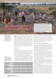
LNG savings of burners - Institute for Industrial Productivity
LNG savings of burners - Institute for Industrial Productivity
LNG savings of burners - Institute for Industrial Productivity

You also want an ePaper? Increase the reach of your titles
YUMPU automatically turns print PDFs into web optimized ePapers that Google loves.
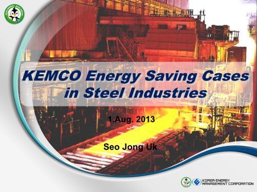
KEMCO Energy Saving Cases<br />
in Steel Industries<br />
1.Aug. 2013<br />
Seo Jong Uk
Ⅱ<br />
Ⅰ<br />
<strong>LNG</strong> saving by adjusting the zone load at heating furnace<br />
<strong>LNG</strong> saving by optimizing the heating furnace pressure<br />
Ⅲ<br />
Increasing power production by preheating BFG<br />
Saving cooling water pump power by installing fluid<br />
Ⅳ coupling system<br />
Ⅴ Increasing combustion air temperature and steam generation<br />
by improving the heat recovery<br />
Preventing the temperature drop <strong>of</strong> preheating zone at furnace<br />
Ⅵ by installing the partition wall<br />
Ⅷ<br />
Ⅶ<br />
<strong>LNG</strong> saving by optimizing the location <strong>of</strong> <strong>burners</strong> in the <strong>for</strong>ge furnace<br />
<strong>LNG</strong> saving <strong>of</strong> <strong>burners</strong> by preheating combustion air
Ⅰ<br />
2/24
▶ Type, Capacity, Size: Pusher Type Heating Furnace, 50ton/h, 6,110W× 2,300L× 4,278H<br />
▶ Number Process <strong>of</strong> block <strong>burners</strong>: diagram Heating Zone 7 Units(Top 5units, Bottom 2 units), Soaking Zone 5 Units<br />
Stack<br />
Combustion<br />
Blower<br />
Exhaust<br />
Blower<br />
Recuperator<br />
Soaking Zone<br />
Burner(5Units)<br />
Top Burner<br />
(5units)<br />
Soaking Zone Heating Zone Preheating Zone<br />
← Charging<br />
Hole<br />
← Out<br />
FL± 0<br />
Bottom Burner<br />
(2units)
▶ [ Process Field measurements flow <strong>for</strong> target shall process] be conducted with test material as follows.<br />
▶ 6 measurement points: ambient temp’(1 point), longitudinal temp’(3 points),<br />
top and bottom temp’(2 points)<br />
Charging<br />
Direction<br />
Ambient Temp’<br />
(Material Top 50mm)<br />
[Instrument<br />
installation]<br />
[Charging]<br />
[Measurement]<br />
Material Top<br />
Surface Temp’<br />
Material Bottom<br />
Surface Temp’<br />
Material Longitudinal<br />
Temp’(Right)<br />
Material Longitudinal<br />
Temp’(Middle )<br />
Material Longitudinal<br />
Temp’(Left)<br />
[Analysis]<br />
[Instrument recovery]<br />
[Extraction]
▶<br />
[ Process<br />
The analysis<br />
flow <strong>for</strong><br />
<strong>of</strong> field<br />
target<br />
measurements<br />
process]<br />
using test material shows that temperature distribution<br />
in the longitudinal side presents a uni<strong>for</strong>m pr<strong>of</strong>ile.<br />
▶ But, the top and bottom temperature range indicates more than 40℃.<br />
Control temp’:<br />
1180℃<br />
Control<br />
temp’ :<br />
1130℃<br />
Preheating Heating Soaking<br />
[Figure: Total Temp’ Pr<strong>of</strong>ile(6points)]<br />
[Figure: Ambient temperature]<br />
Top<br />
Bottom<br />
1120℃<br />
1110℃<br />
Preheating Heating Soaking Preheating Heating Soaking<br />
[Figure: Longitudinal temperature]<br />
[Figure: Top and bottom temperature]
▶ Lower the burner load <strong>of</strong> soacking zone and increase the burner load <strong>of</strong> bottom heating zone<br />
to reduce the top and bottom temperature deviation.<br />
Division<br />
Heating Zone<br />
Top Burner Load(%)<br />
Heating Zone<br />
Bottom Burner Load(%)<br />
Soacking Zone Burner<br />
Load(%)<br />
Be<strong>for</strong>e 57 17 26<br />
After 57 20(Increase) 23(Decrease)<br />
O 2 :Less than 6%<br />
O 2 :5~6%<br />
Decrease the burner load <strong>of</strong><br />
Soaking zone.<br />
O 2 :5~6%<br />
←<br />
Extraction<br />
Soacking Zone Heating Zone Preheating Zone<br />
← Charging<br />
Hole<br />
Increase the burner load <strong>of</strong><br />
heating zone.<br />
O 2 :9%
Energy Savings<br />
(Toe/yr)<br />
Saving Cost<br />
(k$/yr)<br />
Investments<br />
(k$)<br />
Payback<br />
(year)<br />
CO2<br />
Reduction<br />
(tCO2/yr)<br />
259 157 - - 605<br />
• Adjusting the Zone load at heating furnace brings 3% efficiency<br />
improvement.<br />
• Annual <strong>LNG</strong> <strong>savings</strong> <strong>of</strong> <strong>burners</strong>: 246,665Nm3/yr<br />
• <strong>LNG</strong> toe conversion factor: 1.05 toe/kNm3<br />
• <strong>LNG</strong> price per Nm3 : 0.727 $/Nm3<br />
• <strong>LNG</strong> carbon dioxide emission factor per toe: 2.3357tCO2/toe
Ⅱ
▶ Type, Capacity: Large Rolling Heating Furnace, 150ton/h<br />
▶ Burner Process type: block Regenerative diagram burner 21 sets<br />
[Table: Large Rolling Heating Furnace Spec Data]<br />
Divi<br />
sion<br />
Capa(T/h)<br />
Burner<br />
(set)<br />
Lenghth<br />
(m)<br />
FD FAN<br />
ID FAN<br />
Maker<br />
Large<br />
Mill<br />
#1<br />
150<br />
21(+1)<br />
36<br />
43820 m3<br />
1100 mmAq<br />
186 Kw<br />
73620 m3<br />
1250 mmAq<br />
220 Kw<br />
Combustech<br />
FD FAN<br />
ID FAN<br />
Soaking Zone<br />
Heating Zone<br />
Preheating Zone<br />
Regenerative<br />
burner<br />
1265℃ 1250℃ 1230℃
▶ [ Process Large Rolling flow <strong>for</strong> Heating target process] Furnace is operated at a negative pressure(-0.2~0.4mmH2O)<br />
▶ It causes heat loss by invaded fresh air, so the heat loss <strong>of</strong> body exhaust gas<br />
increase.<br />
Stack<br />
Exhaust heat loss from<br />
body accounts <strong>for</strong> 80%<br />
<strong>of</strong> total heat loss.<br />
Current furnace<br />
pressure PV value:<br />
-0.35 mmH2O<br />
Temp : 694℃<br />
O2 : 10.8 %<br />
CO2 : 5.63ppm<br />
Temp :<br />
846.6℃<br />
O2 : 6.7%<br />
CO2 : 0 ppm<br />
Temp : 109 ℃<br />
O2 : 16.1 %<br />
CO2 : 2.78<br />
ppm<br />
Exhaust gas<br />
from body<br />
Exhaust gas<br />
from burner<br />
[Figure: Comparison <strong>of</strong> exhaust gas heat loss ]<br />
[Figure: Current furnace pressure control screen]
▶ The below table shows flue gas temperature and <strong>LNG</strong> usage depending on the furnace<br />
pressure. Those data are obtained through field testing.<br />
[Table: <strong>LNG</strong> usage <strong>of</strong> large rolling heating furnace depending on the furnace pressure changes ]<br />
Time<br />
Furnace<br />
Pressure<br />
Main <strong>LNG</strong><br />
Usage<br />
MAIN Exhaust gas<br />
from body<br />
Exhaust gas<br />
from regenerative burner<br />
2007.9.5 mmAq Nm3/h 온도(℃) O2(%) 온도(℃) O2(%)<br />
16:17 -0.6 1609 875.6 5 122.9 13.8<br />
16:18 -0.4 1758 870(880) 4.2 14.6<br />
16:21 -0.2 1965 828.2 7.4 145.7 13.9<br />
16:26 -0.24 1689 835 4.7 130.8 13.9<br />
16:47 0 1456 831 6 119.6 14.1<br />
16:58 0 1355 833.8 5.4 120.2 14.5<br />
17:16 0.33 1439 831.7 5.2 124.8 14<br />
17:27 0.24 1377 823.2 5.9 124.6 14<br />
17:39 0.3 1301 826.9 5.2 124.1 14<br />
18:00 0.3 1301 821.5 4.9 124.8 13.5<br />
Remark<br />
Main Exhaust<br />
Damper<br />
40% Open<br />
Main Exhaust<br />
Damper<br />
30% Open<br />
Main Exhaust<br />
Damper<br />
28.2% Open
▶ By changing furnace pressure from -0.35mmAq to 0.18 mmAq, <strong>LNG</strong> consumption is reduced<br />
from 1,775Nm3/h to 1,393Nm3/h.<br />
<strong>LNG</strong><br />
Consumption <strong>LNG</strong>사용량<br />
(Nm3/h)<br />
1,900.0<br />
1,700.0<br />
1,500.0<br />
1,300.0<br />
1,100.0<br />
900.0<br />
700.0<br />
로내압 변경에 따른 <strong>LNG</strong> 사용추이<br />
<strong>LNG</strong> Consumption comparison with furnace<br />
pressure changes<br />
(0.35) 0.18 로내압(단위:mmAq)<br />
Furnace<br />
Pressure(mmAq)<br />
main Main <strong>LNG</strong>량<br />
Consumption
▶ We must adjust furnace pressure in order to minimize the heat loss by invaded fresh air<br />
and blow <strong>of</strong>f <strong>of</strong> furnace gas.<br />
▶ Optimum furnace pressure: About 1 mmAq<br />
[Figure: Heat loss table book with furnace pressure changes ]
Energy Savings<br />
(Toe/yr)<br />
Saving Cost<br />
(k$/yr)<br />
Investments<br />
(k$)<br />
Payback<br />
(year)<br />
CO2<br />
Reduction<br />
(tCO2/yr)<br />
2,171 1,503 - - 5,071<br />
• Applied data to calculate improvement effects is as below.<br />
and we apply safety factor to 0.7 considering disturbance.<br />
• Operating hours per year: 8,160h/yr<br />
Furnace<br />
pressure<br />
Main <strong>LNG</strong><br />
consumption<br />
MAIN exhaust<br />
Regenerative burner exhaust<br />
mmAQ Nm3/h Temp’(℃) O2(%) Temp’(℃) O2(%)<br />
-0.35 1,755.3 846.3 5.3 133.1 14.1<br />
0.18 1,393.0 828.0 5.4 123.0 14.0<br />
Distinction 362.3 18.3 -0.1 10.1 0.0
Ⅲ
▶ BLR uses waste gas(BFG, FOG, COG) generated in the smelting process as fuel gas.<br />
But fuel gas is supplied at 20℃ without preheating.<br />
▶ The flue gas from APH is discharged to 185℃ into the atmosphere.<br />
High Pressure<br />
Steam<br />
Exhaust<br />
Gas<br />
B-C<br />
Burner<br />
Extraction<br />
Steam<br />
Power<br />
639GWh<br />
BFW Heater<br />
BFW Pump<br />
* BFG: Blast Furnace Gas, FOG: Finex Off Gas, COG: Coke Oven Gas<br />
[Figure: Power system using BFG]
▶ Power generation increases from 639GWh to 645GWh by preheating BFG.<br />
▶ Heat pipe heat exchanger is installed to preheat BFG with flue gas.<br />
▶ Flue gas temp’ drops from 185℃ to 154℃. but BFG temp’ increases from 20℃ to 80℃.<br />
BFG Preheating<br />
System<br />
High Pressure<br />
Steam<br />
Exhaust<br />
Gas<br />
B-C<br />
Burner<br />
Extraction<br />
Steam<br />
Power<br />
645GWh<br />
BFW Heater<br />
BFW Pump<br />
[Figure: Power system installed with BFG Preheating Heat Exchanger]
▶ Heat pipe exchanger using water as heat exchanger material is installed to preheat BFG.<br />
▶ The water in evaporator is vaporized with flue gas heat and is condensed at condenser<br />
by heating BFG.<br />
To BLR<br />
보일러<br />
BFG<br />
80℃<br />
응축기<br />
Condenser<br />
Stack<br />
배GAS<br />
154℃<br />
Flue Gas<br />
154℃<br />
증기<br />
Steam<br />
증발기<br />
Evaporator<br />
BFG<br />
20℃<br />
BFG배관<br />
BFW Pipe<br />
Condensate<br />
응축액<br />
배GAS<br />
185℃<br />
Flue Gas<br />
185℃<br />
보일러<br />
From BLR<br />
[Figure: Heat Exchanger System to preheat BFG]
Energy Savings<br />
Saving Cost<br />
Investments<br />
Payback<br />
CO2 Reduction<br />
(MWh/yr)<br />
(k$/yr)<br />
(k$)<br />
(yr)<br />
(tCO2/yr)<br />
6,257 563 1,507 2.7 1,507<br />
• Additional power production: 6,256,664 kWh/yr<br />
• Power unit: 0.09$/kWh<br />
• Carbon dioxide emission factor <strong>for</strong> power: 0.8 tCO2/MWh
Ⅳ
▶ 7 cooling water pumps are installed to supply cooling water <strong>for</strong> rolling equipment.<br />
5 cooling water pumps always operate regardless <strong>of</strong> load change.<br />
▶ Cooling Water Pump Design Data: 1,400kW, 6,600V, 125A, 28m3/min, 20kg/cm2g<br />
Roll Cooling Water Pump<br />
Cooling Water Line<br />
Cooing Water Pump: 7 EA<br />
(5 Centrifugal pumps are always operating)<br />
Cooling Water Pipe<br />
Rough rolling Finish rolling Winder<br />
[Figure: Cooling water supply system]
▶ Cooling water pump power can be saved by installing fluid coupling which automatically<br />
adjust motor speed according to the cooling water load.<br />
▶ 4 <strong>of</strong> 7 cooling water pumps should install fluid coupling <strong>for</strong> cooling water load variations.<br />
Roll Cooling Water Pump<br />
Cooling Water Pipe<br />
4 <strong>of</strong> 7 cooling water pumps are<br />
installed with fluid coupling system<br />
Cooling Water Line<br />
Rough rolling<br />
Finish rolling<br />
Winder<br />
[Figure: Cooling water supply system installed with fluid coupling]
▶ Fluid coupling is additionally installed to the existing motors and pumps.<br />
▶ Fluid coupling specifications: variable speed type(20%~80%), direct connection type, 15 sec<br />
acceleration time(lowest RPM → maximum RPM)<br />
Inlet Valve<br />
Cooling Water<br />
Motor<br />
(Existing)<br />
Fluid Coupling (New)<br />
Pump (Existing)<br />
Improvement<br />
Be<strong>for</strong>e/After<br />
[Figure: Fluid coupling system]
Energy Savings<br />
Saving Cost<br />
Investments<br />
Payback<br />
CO2 Reduction<br />
(MWh/yr)<br />
(k$/yr)<br />
(k$)<br />
(yr)<br />
(tCO2/yr)<br />
5,041 458 2,279 5.0 4,033<br />
• Power consumption be<strong>for</strong>e improvement: 41,748,742 kWh/yr<br />
• Power consumption after improvement: 36,707,669 kWh/yr<br />
• Power unit: 0.09$/kWh<br />
• Carbon dioxide emission factor <strong>for</strong> power: 0.8 tCO2/MWh
Ⅴ<br />
25/24
▶ NOF exhaust air volume supplied to recuperator is reduced due to providing part <strong>of</strong><br />
NOF exhaust air to the cleaning dryer<br />
▶ Air leak <strong>of</strong> recuperator tube side causes the temperature drop <strong>of</strong> combustion air<br />
Steam production is<br />
reduced due to the decrease<br />
<strong>of</strong> exhaust air flow.<br />
Recuperator tubes are<br />
damged<br />
Cold Air<br />
Part <strong>of</strong> NOF exhaust air is<br />
provided to cleaning dryer.<br />
[Figure: NOF zone supply and exhaust air system]
▶ Through the supply and exhaust air balance analysis, we know that 15% <strong>of</strong> supply air leaks<br />
at recuperator tubes.<br />
▶ 48% <strong>of</strong> the hot exhaust air is supplied to the cleaning dryer.<br />
[Table: NOF zone supply and exhaust air balance]<br />
Division<br />
Volume<br />
(Nm 3 /h)<br />
Percent<br />
(%)<br />
Temp’<br />
(℃)<br />
NOF Comb’ Air 4,800 36.9 200<br />
Remark<br />
After Burner 900 6.9 200<br />
Supply<br />
Air Balance<br />
Air Curtain 4,800 36.9 20<br />
Air Leak 2,000 15.4 20 O2% : 4%→7%(Increase)<br />
Exhaust<br />
Air Balance<br />
By-Pass 500 3.8 200<br />
Sub Total 13,000 100.0<br />
To Recup' 3,222 51.8 634<br />
To Cleaning Dryer 3,000 48.2 634<br />
Sub Total 6,222 100.0<br />
O2% <strong>of</strong> Hot Air supplied to cleaning<br />
dryer O2% is about 15.5%.
▶ According to linear regression analysis <strong>of</strong> steam generation compared to burner <strong>LNG</strong><br />
consumption, #1 CGL steam generation is half <strong>of</strong> #2 CGL.<br />
▶ As part <strong>of</strong> hot exhaust air is supplied to the pretreatment cleaning dryer,<br />
We confirm that the reduced exhaust airflow is the main reason.<br />
2.50<br />
2.00<br />
1.50<br />
1.00<br />
0.50<br />
#1 CGL 폐열BLR 스팀생산량(m 3 /h)<br />
(ton/h) VS <strong>LNG</strong> 분석 Consumption(Nm3/h)<br />
#1 CGL Waste Heat Boiler Steam Generation<br />
y = 0.0006x<br />
R²= 0.5024<br />
2.50<br />
2.00<br />
1.50<br />
1.00<br />
0.50<br />
#2 CGL 폐열BLR 스팀생산량(m 3 /h)<br />
(ton/h) VS <strong>LNG</strong> 분석 Consumption(Nm3/h)<br />
#2 CGL Waste Heat Boiler Steam Generation<br />
y = 0.0011x<br />
R²= 0.3976<br />
0.00<br />
- 200 400 600 800 1,000 1,200<br />
Steam Generation<br />
Line(Steam<br />
스팀생산량(m3/h)<br />
(ton/h)<br />
线 性 (스팀생산량(m3/h))<br />
Generation(ton/h))<br />
0.00<br />
- 500 1,000 1,500 2,000<br />
Steam Generation<br />
Line(Steam<br />
스팀생산량(m3/h) 线 性 (스팀생산량(m3/h))<br />
(ton/h)<br />
Generation(ton/h))
▶ By stop exhaust gas to cleaning dryer and replacing tubes <strong>of</strong> recuperator,<br />
the temperature <strong>of</strong> combustion air rises from 200℃ to 300℃ and the steam generation<br />
at waste heat boiler increases from 496kg/h to 1,097kg/h<br />
Exhaust gas mixed with OA is<br />
supplied to cleaning dryer.<br />
The temp’ <strong>of</strong> combustion air<br />
Increases from 200℃ to 300℃<br />
Cut <strong>of</strong>f part <strong>of</strong> NOF exhaust air<br />
provided to cleaning dryer.<br />
[Figure: NOF zone supply and exhaust air improvement system]
▶Data be<strong>for</strong>e and after improvement are shown in the table below.<br />
▶ <strong>LNG</strong> used in <strong>burners</strong> is saved and steam is additionally generated only through<br />
cutting <strong>of</strong>f NOF exhaust air supplied to cleaning dryer<br />
[Table: Operating data be<strong>for</strong>e and after improvement]<br />
Divsion Be<strong>for</strong>e After<br />
Increase<br />
And<br />
Decrease<br />
Remark<br />
NOF Combustion Air Temp’(℃) 200 300 +100 100℃ Increase<br />
Recuperator Air Leak(Nm 3 /h) 2,000 0 - 2,000 Replace recuperator tubes<br />
NOF Exhaust Airflow<br />
to Cleaning Dryer(Nm 3 /h)<br />
3,000 0 -3,000 Stop NOF exhaust air supplied to cleaning dryer<br />
Recuperator Exhaust Flow(Nm 3 /h) 3,222 6,222 +3,000<br />
Exhaust gas temp’<br />
be<strong>for</strong>e recuperator(℃)<br />
Exhaust gas temp’<br />
after recuperator (℃)<br />
#1 CGL Waste Heat Boiler<br />
Steam Generation(kg/h)<br />
634 634 - No Change<br />
219 385 +166<br />
496 1,097 +601<br />
Exhaust air increase by cutting <strong>of</strong>f NOF exhaust<br />
air to cleaning dryer.<br />
The exhaust gas temperature after recuperator<br />
rises due to the increase <strong>of</strong> exhaust airflow.<br />
The steam generation <strong>of</strong> #1 CGL waste heat<br />
boiler increases.
Energy Savings<br />
Saving Cost<br />
Investments<br />
Payback<br />
CO2 Reduction<br />
(Toe/yr)<br />
(k$/yr)<br />
(k$)<br />
(yr)<br />
(tCO2/yr)<br />
297 218 94 0.4 323<br />
• <strong>LNG</strong> <strong>savings</strong> <strong>of</strong> <strong>burners</strong>: 38,255 Nm3/yr<br />
• <strong>LNG</strong> toe conversion factor: 1.05 toe/kNm3<br />
• <strong>LNG</strong> price per Nm3 : 0.727 $/Nm3<br />
• Additional steam production: 4,760 ton/yr<br />
• Steam toe conversion factor: 0.0539 toe/ton<br />
• Steam price per ton: 40 $/ton<br />
• <strong>LNG</strong> carbon dioxide emission factor per toe: 2.3357tCO2/toe<br />
• Steam carbon dioxide emission factor per ton: 0.0491tCO2/ton
Ⅵ
▶ If door will be opened, you can see that cold air from the outside would be significantly<br />
introduced to the deep point without partition wall.<br />
▶ Influx <strong>of</strong> cold air at the bottom <strong>of</strong> the furnace increases the amount <strong>of</strong> burner <strong>LNG</strong><br />
O 2 :8~9%<br />
O 2 :16%<br />
O 2 :11~12%<br />
←<br />
Discharge<br />
Soaking zone<br />
Heating zone<br />
Preheating zone<br />
←<br />
Charging<br />
Hole<br />
Cold air from the outside is<br />
introduced to the bottom <strong>of</strong> furnace<br />
O 2 :9%<br />
[Figure: Heating Furnace Operating Diagram ]<br />
[Figure: Fluent analysis <strong>of</strong> current operating condition at heating furnace ]
[Case 1: Installing partition wall at 2 meter from charging side]<br />
▶ Partition wall cut <strong>of</strong>f the cold air supplied from the outside. but you can see that<br />
part <strong>of</strong> cold air is introduced to the bottom <strong>of</strong> preheating zone over the partition wall<br />
Part <strong>of</strong> cold air from the outside is<br />
prevented from partition wall<br />
Part <strong>of</strong> cold air from the outside is<br />
introduced to the bottom <strong>of</strong> furnace<br />
[Figure: Fluent analysis in case <strong>of</strong> installing partition wall at 2 meter from charging side]
[Case 2: Installing partition wall at 4.2 meter from charging side]<br />
▶ The rear temperature <strong>of</strong> partition wall keeps higher than case 1. you can see the<br />
uni<strong>for</strong>m temperature pr<strong>of</strong>ile at the bottom <strong>of</strong> preheating zone due to the prevention <strong>of</strong> cold air.<br />
▶ The effect to en<strong>for</strong>ce preheating with partition wall causes the <strong>LNG</strong> saving <strong>of</strong> burner<br />
The temperature pr<strong>of</strong>ile at the<br />
bottom <strong>of</strong> preheating zone is higher<br />
than case 1.<br />
[Figure: Fluent analysis in case <strong>of</strong> installing partition wall at 4.2 meter from charging side]
[Case 3: Installing partition wall at 6.3 meter from charging side]<br />
▶ Because partition wall is installed at 6.3 meter from charging hole, the front temperature <strong>of</strong><br />
charging side keeps low.<br />
▶ the preheating effect appears lower than case 2 because <strong>of</strong> the long distance(6.3meter)<br />
from charging hole.<br />
The front temperature <strong>of</strong> charging<br />
side keeps low and this results in the<br />
increase <strong>of</strong> <strong>LNG</strong> consumption at<br />
<strong>burners</strong><br />
[Figure: Fluent analysis in case <strong>of</strong> installing partition wall at 6.3 meter from charging side]
Energy Savings<br />
Saving Cost<br />
Investments<br />
Payback<br />
CO2 Reduction<br />
(Toe/yr)<br />
(k$/yr)<br />
(k$)<br />
(yr)<br />
(tCO2/yr)<br />
406 281 44 0.2 949<br />
• Annual <strong>LNG</strong> <strong>savings</strong> <strong>of</strong> <strong>burners</strong>: 386,863 Nm3/yr<br />
• <strong>LNG</strong> toe conversion factor: 1.05 toe/kNm3<br />
• <strong>LNG</strong> price per Nm3 : 0.727 $/Nm3<br />
• <strong>LNG</strong> carbon dioxide emission factor per toe: 2.3357tCO2/toe
Ⅶ
▶ Analyze results <strong>for</strong> heat flow <strong>of</strong> the <strong>for</strong>ge furnace with Fluent simulation*<br />
- Temperature pr<strong>of</strong>ile : Not uni<strong>for</strong>m (maximum temperature difference : 36 o C)<br />
[Heat pr<strong>of</strong>ile <strong>for</strong> operating conditions <strong>of</strong> the <strong>for</strong>ge furnace]<br />
□ There were 16 <strong>burners</strong><br />
Ro<strong>of</strong> burner : 4 set x 2(reft/right)<br />
Side burner :4 set x 2(reft/right)<br />
* Fluent is a flow modeling and continuous fluid dynamic simulator (CFD).<br />
□ Lower side <strong>burners</strong> are absence<br />
- Temperature pr<strong>of</strong>ile : not uni<strong>for</strong>mity<br />
- Maximum temperature difference in the <strong>for</strong>ge : 36 o C
▶ Analyze heat flow <strong>of</strong> the flue gas with Fluent simulation<br />
- Uneven flue gas distribution<br />
[Heat pr<strong>of</strong>ile <strong>for</strong> operating condition <strong>of</strong> flue gas]<br />
□ Flame direction <strong>of</strong> ro<strong>of</strong> <strong>burners</strong><br />
: biased to left side<br />
(A part <strong>of</strong> Ingots overheated)<br />
□ Gas distribution <strong>of</strong> side <strong>burners</strong><br />
: Flames are not overlapped<br />
□ Gas distribution <strong>of</strong> the upper section<br />
: active compare with the lower section<br />
□ Flue gas distribution<br />
: concentrated to the left side
▶ Comparison data <strong>of</strong> be<strong>for</strong>e and after improvement<br />
- <strong>LNG</strong> saving by optimizing <strong>burners</strong> location(<strong>LNG</strong> <strong>savings</strong>:2.7%).<br />
[ Heat pr<strong>of</strong>ile be<strong>for</strong>e and after improving]<br />
Be<strong>for</strong>e improving<br />
After improving<br />
■ Side, Ro<strong>of</strong> BNR( ) Pitch: 3,300 mm<br />
■ Relocate Ro<strong>of</strong> BNR to side(Pitch: 3,300 mm)<br />
■ Distance between Side BNR(●) and charge door :1,350mm ■ Distance between Side BNR(●) and charge door :1,000mm<br />
■ Distance between Side BNR(●) and charge door :3,000mm ■ Distance between Side BNR(●) and charge door :2,100mm<br />
■ Maximum △T <strong>of</strong> Ingots : 36℃<br />
<strong>LNG</strong> consumed : 4,183 Nm3/yr<br />
■ Maximize △T <strong>for</strong> high efficiency and quality<br />
<strong>LNG</strong> consumed : 4,070 Nm3/yr<br />
(2.7% <strong>LNG</strong> <strong>savings</strong>)<br />
■ Maximum △T <strong>of</strong> Ingots : 21℃ (15℃ decreased)<br />
■ Adjust the angle <strong>of</strong> ro<strong>of</strong> and side burner : -8 o
▶ Comparison data <strong>of</strong> be<strong>for</strong>e and after improvement<br />
- More uni<strong>for</strong>m temperature pr<strong>of</strong>ile by optimizing <strong>burners</strong> location<br />
[ Temperature pr<strong>of</strong>ile <strong>of</strong> be<strong>for</strong>e and after improvement]<br />
Be<strong>for</strong>e improvement<br />
(Side View - L ) (Side View - R )<br />
After improvement<br />
(Side View - L ) (Side View - R )<br />
(Upper View )<br />
(Upper View )<br />
(Bottom View )<br />
(Bottom View )
Energy Savings<br />
Saving Cost<br />
Investments<br />
Payback<br />
CO2 Reduction<br />
(Toe/yr)<br />
(k$/yr)<br />
(k$)<br />
(yr)<br />
(tCO2/yr)<br />
119 82 60 0.7 278<br />
• <strong>LNG</strong> toe conversion factor: 1.05 toe/kNm3<br />
• <strong>LNG</strong> price per Nm3 : 0.727 $/Nm3<br />
• <strong>LNG</strong> carbon dioxide emission factor per toe: 2.3357tCO2/toe<br />
Energy saving items As Is To Be Savings Saving cost<br />
<strong>LNG</strong> consumption 4,183 kNm 3 /yr 4,070 kNm 3 /yr 113 kNm 3 /yr k$ 82/yr
Ⅷ
▶ Without preheating the combustion air, it increases the <strong>LNG</strong> consumption.<br />
▶ Heat loss happens generally by heating cold air from 20℃ to 20℃.<br />
COLD AIR (20 o C)<br />
Heat loss happens by heating air from<br />
20℃ to 20℃.<br />
Air 20C<br />
Combustion(Flam<br />
e)<br />
=> HEATING<br />
ENERGY<br />
RECUPERATIVE<br />
(500 o C)<br />
Air 500C<br />
25% saving<br />
Heat loss happens by heating<br />
air from 500℃ to 1200℃.<br />
HEATING MATERIAL<br />
AIR<br />
REGENERATIVE(1000<br />
o<br />
C)<br />
50% saving<br />
25% saving<br />
Heat loss happens by<br />
heating air from<br />
1000℃ to 1200℃.<br />
Air 1000C<br />
20C<br />
500C<br />
1000C<br />
1200C
[ Combustion air temperature be<strong>for</strong>e burner and energy saving]<br />
COLD<br />
AIR TYPE<br />
AIR PREHEATING (BY FLUE GAS)<br />
CONCENTRATIVE TYPE<br />
INDIVIDUAL TYPE<br />
RADIATION CONVECTION SELF-RECUPER REGENERATIVE<br />
AIR TEMP(@1200C) 20C 450C 600C 800C 1100C<br />
FUEL SAVING - 20% 25% 35% 45%<br />
APPLICATION<br />
OTHERS<br />
ALL<br />
HEATTREATING<br />
FORGING (~1200C)<br />
ROLLING, FORGING<br />
(OVER 1100C)<br />
HEATTREATING<br />
( ~1100C)<br />
ROLLING, FORGING<br />
(OVER 1100C)<br />
COST VERY LOW LOW MIDIUM HIGH HIGH<br />
• SIMPLE<br />
• SIMPLE<br />
• AIR PIPING SIZE UP<br />
• RECUPERATOR<br />
MAITENANCE(2YEAR)<br />
• AIR PIPING SIZE UP<br />
• EX-GAS PIPING<br />
• AIR FAN CAPA UP<br />
(1.5TIMES)<br />
• SIMPLE<br />
• COMPLEX and SIZE UP<br />
• EX-GAS PIPING<br />
• NEED ADDITIONAL IDF
1). Characteristics<br />
2). Application<br />
• Continuous Heat treatment Furnace<br />
• Forge Heat treatment Furnace<br />
• Aluminum Heat treatment Furnace<br />
• Preheat Furnace
A. REGENERATIVE BURNER B. REGENERATIVE COMBUSTION SYSTEM<br />
BURNER<br />
HEAD<br />
PILOT<br />
BURNER<br />
FUEL CYCLE<br />
VALVE<br />
1 ST AIR CYCLE<br />
VALVE<br />
REGEN BURNER<br />
B<br />
Pilot Burner & UV Scanner<br />
REGEN BURNER<br />
A<br />
MEDIA CASE<br />
2 ND AIR CYCLE<br />
VALVE<br />
EX-GAS CYCLE<br />
VALVE<br />
REGENERATIVE<br />
MEDIA<br />
FUEL.1,2AIR.EXHAUST GAS<br />
FLOW CONTROL UNIT<br />
SAFETY DEVICE<br />
EACH UTILITY,<br />
PRESSURE,FLOW,TEMPERATU<br />
RE MEASURING DEVICE
49/24