

Simple AutoCAD tutorial for beginners - Leslie Shor
Simple AutoCAD tutorial for beginners - Leslie Shor
Simple AutoCAD tutorial for beginners - Leslie Shor

You also want an ePaper? Increase the reach of your titles
YUMPU automatically turns print PDFs into web optimized ePapers that Google loves.
Principles and Applications of Microfluidic Devices<br />
<strong>AutoCAD</strong> Design Lab - COMSOL import ready<br />
Part I. Introduction<br />
<strong>AutoCAD</strong> is a computer drawing package that can allow you to define physical structures <strong>for</strong><br />
subsequent creation of a custom photolithography mask. The functions of the <strong>AutoCAD</strong> program allow<br />
you to build shapes, mirror or copy objects, align and join them together, and organize objects into<br />
defined layers.<br />
In this lab, we will be drawing a simple microfluidic device together to help you become more familiar<br />
with how to use <strong>AutoCAD</strong>. Our goal is to give you practice using a large range of different commands<br />
you will find most useful in drawing your own designs.<br />
The software is available <strong>for</strong> you to download; un<strong>for</strong>tunately UConn does not have a site license <strong>for</strong><br />
<strong>AutoCAD</strong> so we cannot use the SOE computer labs.<br />
Mask Concept<br />
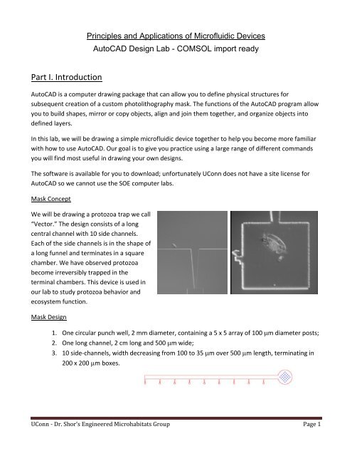
We will be drawing a protozoa trap we call<br />
“Vector.” The design consists of a long<br />
central channel with 10 side channels.<br />
Each of the side channels is in the shape of<br />
a long funnel and terminates in a square<br />
chamber. We have observed protozoa<br />
become irreversibly trapped in the<br />
terminal chambers. This device is used in<br />
our lab to study protozoa behavior and<br />
ecosystem function.<br />
Mask Design<br />
1. One circular punch well, 2 mm diameter, containing a 5 x 5 array of 100 m diameter posts;<br />
2. One long channel, 2 cm long and 500 m wide;<br />
3. 10 side‐channels, width decreasing from 100 to 35 m over 500 m length, terminating in<br />
200 x 200 m boxes.<br />
UConn - Dr. <strong>Shor</strong>’s Engineered Microhabitats Group Page 1
UConn - Dr. <strong>Shor</strong>’s Engineered Microhabitats Group Page 2
Part II. Step‐by‐Step Instructions<br />
1. Preliminaries:<br />
a. Launch <strong>AutoCAD</strong> with the default template.<br />
b. Define preferences. Type OSNAP: make sure the following are checked: Endpoint, Midpoint,<br />
Center, Intersection, Extension, and Parallel.<br />
c. Make sure hardware acceleration is on. Click button to the right of padlock icon on lower right.<br />
d. All commands are written below in caps. You need to type the command (but <strong>AutoCAD</strong> is not<br />
case‐sensitive, and some have short‐cuts). By hitting space bar or enter you will be prompted<br />
through options relating to the command. Look at the command bar at the bottom of the screen<br />
to determine the details of your prompts.<br />
e. Remember these tips:<br />
i. To cancel a selection or a command press ESC.<br />
ii. You usually need to press spacebar/enter after every input of a command<br />
iii. Mouse selection techniques: right to left selects everything touching box, left to right<br />
selects things only inside the box.<br />
2. Draw a CIRCLE radius 1000<br />
a. (Type “circle”, hit space bar, and then click on position in space, type in radius 1000. You don’t<br />
see anything, because the circle is so large. You must now zoom out. ZOOM, then type EXTENTS<br />
at the prompt)<br />
3. Draw a RECTANGLE Length 500 width 3000<br />
a. (type RECTANGLE, specify a starting point, Type “D” <strong>for</strong> dimensions, then follow inputs <strong>for</strong><br />
length and width, click to place)<br />
4. MOVE the midpoint of the top line of the rectangle on the center of the circle (make sure you have<br />
midpoint and center checked on OSNAP)<br />
a. Type MOVE, select the object(s) you want to move, click on the point you want to move in<br />
reference to, then drag and click to place your object<br />
5. Trim the rectangle out of the center of the circle so it sorta looks like a keyhole<br />
a. Type TRIM, click on circle <strong>for</strong> the cutting edge, space bar, and then click on the object you want<br />
to cut i.e. the rectangle part inside the circle, then spacebar/enter to finish.<br />
6. EXPLODE the rectangle and ERASE the bottom line and the left line<br />
UConn - Dr. <strong>Shor</strong>’s Engineered Microhabitats Group Page 3
a. The vertical line on the right shall be known as line A<br />
7. Draw a 500 unit long line to the right from the bottom of line A. This shall be line B (type LINE, click<br />
starting place, move mouse in the direction where you want it, type in 500, spacebar. The command<br />
LINE assumes you want to make a subsequent line. Just hit escape.)<br />
8. Draw a 17.5 unit long line straight up from the end of line B. This shall be line C.<br />
9. Draw a 50 unit long line straight up from the left side of line B. This is Line D<br />
a. This should overlap your previous vertical line, and you won’t be able to see it. This is ok.<br />
10. Connect the top of D with the top of C with a LINE (should be about 501.0551 long)<br />
11. MIRROR the previous line about the horizontal line<br />
a. Type MIRROR, select the object you want to duplicate, spacebar, select 2 points on B to use as<br />
the axis of reflection, choose No <strong>for</strong> deleting original line.<br />
12. Create a RECTANGLE of dimensions 200x200<br />
UConn - Dr. <strong>Shor</strong>’s Engineered Microhabitats Group Page 4
13. Align Line B with the midpoint of the left edge of the square. (MOVE, space, click midpoint of square,<br />
click end of line B.)<br />
14. ERASE lines B, C, D.<br />
15. TRIM the vertical line to the sloped line by using the sloped lines as the cutting edge.<br />
16. TRIM the part of the square between the two sloped lines using the 2 sloped lines as the cutting edges.<br />
17. Select everything but the partial circle (drag mouse from right to left but don’t touch the circle)<br />
18. Type ARRAY<br />
a. Rectangle<br />
b. Type B <strong>for</strong> Basepoint and click on the top of the vertical line where it connects to the circle<br />
c. Type C <strong>for</strong> count, 10 rows, 1 column<br />
d. Type S <strong>for</strong> spacing and then click on the left end of the bottom angled line.<br />
e. exit<br />
UConn - Dr. <strong>Shor</strong>’s Engineered Microhabitats Group Page 5
19. Draw a 500 unit horizontal LINE starting on the very bottom sloped line.<br />
20. Click the portion of the vertical line nearest to the circle previously labeled A.<br />
21. EXPLODE and select this line again.<br />
22. OFFSET this line 500 um to the left<br />
a. Type OFFSET <br />
b. 500 <br />
c. then click on the left side<br />
23. EXTEND this line down to the bottom<br />
a. Type EXTEND<br />
b. Select where you want to extend to (the line you drew in step 19)<br />
c. Click on the line you want to extend (the line you made in step 21)<br />
Your main device is DONE!<br />
This is where you have 2 choices on how to proceed, <strong>for</strong> COMSOL modeling or <strong>for</strong> mask production.<br />
When first designing a device you should do COMSOL modeling to make sure you have the right<br />
dimensions and types of flows <strong>for</strong> your needs.<br />
After perfecting your design (multiple iterations of <strong>AutoCAD</strong>/COMSOL models) you will be ready <strong>for</strong><br />
mask production.<br />
These two avenues have different requirements <strong>for</strong> the end <strong>AutoCAD</strong> product. Thus make a saved<br />
archive copy of the <strong>AutoCAD</strong> file you are currently using so you can go back to it in the future.<br />
COMSOL Production Requirements:<br />
1. Clean <strong>AutoCAD</strong> device – no extraneous lines, completely closed regions,<br />
2. Different areas the of the device that will be at different heights will need to be:<br />
a. Completely separate closed objects<br />
b. On different layers labeled well enough to know the object/height by reading just the layer<br />
name<br />
UConn - Dr. <strong>Shor</strong>’s Engineered Microhabitats Group Page 6
Customization <strong>for</strong> COMSOL<br />
Since the big circle at the top will actually be a tall punch through the PDMS and the other parts of the<br />
device are only 50 microns tall we will have to separate them into different objects and then into<br />
different layers.<br />
1. Go back to the top of the device near the circle.<br />
2. Create an arc with the same radius of curvature as the circle between the two vertical lines (HINT:<br />
ARCs always travel counterclockwise in <strong>AutoCAD</strong>, don’t ask me why) And yes this will create an arc<br />
over the existing part of the circle. You won’t be able to see your arc yet.<br />
a. ARC, then click on the top of the left vertical line<br />
b. Then type C <strong>for</strong> center, choose the center of the circle.<br />
c. Click on the top of the right vertical line.<br />
3. Type in LAYER<br />
4. Add two layers using the button in the square box in the figure below<br />
5. Make one red named 50 microns and one blue named 10000 microns<br />
UConn - Dr. <strong>Shor</strong>’s Engineered Microhabitats Group Page 7
a. Click the boxes labeled color (in the black box)<br />
b. Exit the Layer dialog box<br />
6. Select the circle and change to the blue layer by selecting the drop down menu above the word<br />
“layers” in the toolbar<br />
7. Lock the blue layer by clicking the padlock symbol in the dropdown menu<br />
8. Now hide it by clicking on the light bulb.<br />
9. Select everything else and change it to the red layer<br />
10. Now we need to make all lines continuous closed surfaces. This is essential in mask fabrication and<br />
COMSOL drawing to make sure you have continuous lines with no breaks and completely closed<br />
objects.<br />
a. Type PEDIT <br />
UConn - Dr. <strong>Shor</strong>’s Engineered Microhabitats Group Page 8
. Type m <br />
c. select all the lines in the red layer (can drag mouse on each edge) <br />
d. “Convert Lines, Arcs and Splines to polylines (Y) <br />
e. Select Join with a fuzz distance of 3 <br />
f. Make sure command line says: “x segments added to ONE polyline.”<br />
g. This command is an extremely finicky operation, and takes much patience when dealing<br />
with your created objects.<br />
h. The more you have to edit your device the more complicated this command can get. There<br />
is a lot of troubleshooting <strong>for</strong> this command. See appendix <strong>for</strong> help.<br />
11. Make sure the device is closed using the properties of the object<br />
a. Select the object, right click on the object, go to properties, and scroll all the way down.<br />
Does it say “closed”?<br />
12. To import into COMSOL you must save it as a 2010 <strong>AutoCAD</strong> .dxf file.<br />
You’re done with <strong>AutoCAD</strong> aspect of your COMSOL modeling!<br />
To import <strong>AutoCAD</strong> drawing into 3D Comsol with<br />
different heights:<br />
This is composed of two main parts: <strong>AutoCAD</strong> set up, and Importing. If you have a problem it will most<br />
likely be in your setting up of the <strong>AutoCAD</strong> drawing, as the COMSOL is relatively straight <strong>for</strong>ward.<br />
Part I <strong>AutoCAD</strong> file Setup<br />
1. Make your design in <strong>AutoCAD</strong>.<br />
- For every different height in the 3D model you need to create a different layer in <strong>AutoCAD</strong>.<br />
(i.e. your microfluidic channel is 100 microns high is one layer, your punches which are 50000<br />
microns high are another layer.) Make sure you label the layers to be easily identifiable.<br />
- You can only import closed objects (use PEDIT)<br />
-Thus when you have connections between channels or geometries of different heights, those<br />
objects in <strong>AutoCAD</strong> will need to have common overlapping lines/arcs. Sometimes COMSOL<br />
UConn - Dr. <strong>Shor</strong>’s Engineered Microhabitats Group Page 9
has a problem interpreting these overlaps due to COMSOL’s lower resolution of coordinates.<br />
Thus you might need to slightly overlap the closed objects just to be able to connect them in<br />
COMSOL.<br />
-Geometries inside your device need to be on another layer as well. i.e. posts or larger PDMS full<br />
areas. This is done so that you can extrude them separately and then do some Boolean operations<br />
to delete them from the original geometry.<br />
2. Save your <strong>AutoCAD</strong> drawing as a <strong>AutoCAD</strong> 2010 DXF file.<br />
Example: A punch with a microfluidic channel: You must close your punch and put into layer "Punch<br />
Layer". You must close off your channel and use PEDIT to join and close the entire channel and put into<br />
another layer "Channel Layer". Save as <strong>AutoCAD</strong> DXF file.<br />
Part II COMSOL Import<br />
1. Startup COMSOL<br />
2. Select 3D Dimension Space, right arrow, your physics model, right arrow, Time dependent, flag.<br />
3. Set the correct units in Geometry (usually microns)<br />
4. Right click on Geometry and select Work Plane (Do this multiple times <strong>for</strong> each different height you<br />
want)<br />
5. Then right click on Geometry under the Work Plane tab you just created and Click Import and browse<br />
<strong>for</strong> the DXF file.<br />
6. Then use the drop down menu labeled "Layers" and pick "Selected".<br />
7. Select the layer you would like to import <strong>for</strong> that work plane, and click the button “Import”<br />
- For each work plane you must import a different layer.<br />
8. Then right click each work plane and pick “Extrude” to extrude the layer a certain distance to create a<br />
3D object.<br />
a) For each extrusion pick the work plane in the drop down menu, and make sure the object you<br />
want to extrude is in the input objects box. If not then click on the object in the picture and then<br />
click on the plus button next to the input objects box.<br />
UConn - Dr. <strong>Shor</strong>’s Engineered Microhabitats Group Page 10
) Specify the height of the object using the Distances from Work Plane tab in the Extrude<br />
settings.<br />
9. Then build all in the Geometry tab. If you’re having trouble with the union try increasing the repair<br />
tolerance or see below <strong>for</strong> <strong>AutoCAD</strong> tips.<br />
For posts or inside geometries, you will extrude much more than the channel it is in. Then move it<br />
vertically so that the extrusion penetrates both top and bottom of the channel. Use the Boolean operator<br />
to subtract that extrusion from the channel. And voila you’ve got a channel minus posts.<br />
It can be a little finicky and sometimes it just will not recognize your geometries in a layer. You can try<br />
to modify the CAD drawing to fix this or if it’s a simply geometry like a cylinder you can get the info<br />
(x,y coordinate of center) from <strong>AutoCAD</strong> and manually build it in COMSOL. It uses the same<br />
coordinate system between <strong>AutoCAD</strong> and COMSOL.<br />
Now <strong>for</strong> the Mask production.<br />
Once you have your design the way you want it, and have correctly modeled it in COMSOL you will need<br />
to make the device design ok <strong>for</strong> production. This has a separate set of rules of which you can see in the<br />
appendix.<br />
DONE!<br />
UConn - Dr. <strong>Shor</strong>’s Engineered Microhabitats Group Page 11