View Brochure - Val-Matic Valve and Manufacturing Corp.
View Brochure - Val-Matic Valve and Manufacturing Corp.
View Brochure - Val-Matic Valve and Manufacturing Corp.

Create successful ePaper yourself
Turn your PDF publications into a flip-book with our unique Google optimized e-Paper software.
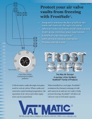
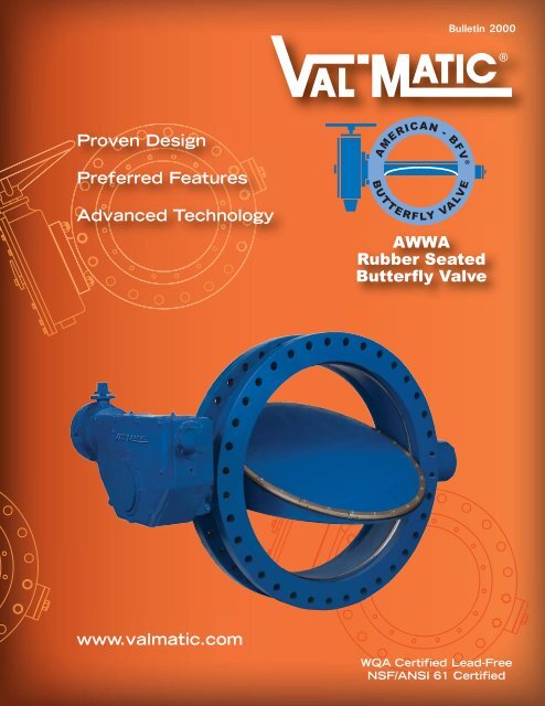
Bulletin 2000<br />
Proven Design<br />
Preferred Features<br />
Advanced Technology<br />
AMERICAN - BFV ®<br />
B U T T E R F LY VA LV E<br />
AWWA<br />
Rubber Seated<br />
Butterfly <strong>Val</strong>ve<br />
www.valmatic.com<br />
WQA Certified Lead-Free<br />
NSF/ANSI 61 Certified
Feature Highlights<br />
I<br />
J<br />
H<br />
G<br />
F<br />
K<br />
E<br />
A<br />
B<br />
C<br />
D<br />
*WQA Certified Lead Free<br />
*NSF/ANSI 61 Certified<br />
A. Body<br />
Available in Wafer, Flanged,<br />
Mechanical Joint <strong>and</strong> Flange x<br />
Mechanical Joint End Connections in<br />
AWWA Classes 150B <strong>and</strong> 250B.<br />
B. Body Seat<br />
360° uninterrupted body seat with<br />
no shaft penetration insures leak<br />
free performance. Type 316 Stainless<br />
Steel provides long life <strong>and</strong> corrosion<br />
free mating surface for resilient seat.<br />
C. Ductile Iron Disc<br />
Ductile Iron provides strength <strong>and</strong><br />
rigidity to withst<strong>and</strong> dynamic forces<br />
from flow <strong>and</strong> pressure transients.<br />
The added strength allows the disc<br />
design to have a smaller cross section<br />
providing improved headloss characteristics.<br />
D. Rubber Seat<br />
Special formulated elastomers for<br />
chemical resistance <strong>and</strong> long cycle<br />
2<br />
life. The 360° resilient seat is uninterrupted<br />
for positive seating.<br />
E. Shaft<br />
Stainless Steel shafts meet AWWA<br />
C504 diameter requirements.<br />
Through-shafts provided st<strong>and</strong>ard on<br />
sizes 3”- 24” <strong>and</strong> available on 30”<br />
<strong>and</strong> larger when specified.<br />
F. Tangential Taper Pins<br />
Stainless Steel Taper Pins with lock<br />
nut <strong>and</strong> o-ring seal utilize tangential<br />
forces of the taper pin <strong>and</strong> lock nut<br />
to provide the most secure method<br />
available of locking the disc to the<br />
shaft.<br />
G. Tri-Loc Seat<br />
Retention System<br />
With over 35 years of proven<br />
dependability the Tri-Loc Seating<br />
System is easily adjusted <strong>and</strong> field<br />
replaceable. All seat hardware is<br />
Type 316 Stainless Steel.<br />
H. Traveling Nut Actuator<br />
The traveling nut design provides<br />
characterized closure during the last<br />
half of travel. Exclusive externally<br />
adjustable stops are rated to 450 ftlbs<br />
of input torque. St<strong>and</strong>ard FA10<br />
motor mounting flange provides<br />
ease of automation.<br />
I. Shaft Seal<br />
Shaft seal is a self-adjusting/wear<br />
compensating V-Type packing. Packing<br />
is easily replaced without<br />
removal of the valve from the line.<br />
J. Sleeve Bearings<br />
Low friction bearings are self-lubricating<br />
<strong>and</strong> non-corrosive, for a<br />
long, trouble-free life.<br />
K. Thrust Bearing<br />
Factory-set bronze thrust bearing<br />
assures proper centering of valve<br />
disc. Thrust bearings are field<br />
adjustable in sizes 30” <strong>and</strong> larger.
Feature Benefits<br />
PROVEN<br />
DESIGN<br />
The American-BFV ® is designed,<br />
manufactured, <strong>and</strong> tested to meet<br />
all AWWA C504 <strong>and</strong> C516 requirements<br />
including performance<br />
tests, leakage tests, <strong>and</strong> hydrostatic<br />
testing. Third-party Proof of<br />
Design Testing was successfully<br />
completed <strong>and</strong> flow testing was<br />
performed at the Utah State<br />
Hydraulics Lab, one of the premier<br />
testing labs in the world.<br />
With thous<strong>and</strong>s of field installations<br />
throughout the world, the<br />
American-BFV ® design has proven<br />
dependable since 1971.<br />
The valves are certified for use in<br />
drinking water in accordance with<br />
NSF/ANSI 61 <strong>and</strong> are WQA<br />
Certified Lead-Free.<br />
PREFERRED<br />
FEATURES<br />
The American-BFV ® provides the<br />
features that engineers <strong>and</strong> users<br />
have requested <strong>and</strong> are included<br />
in the AWWA C504 <strong>and</strong> C516<br />
Butterfly <strong>Val</strong>ve st<strong>and</strong>ards. The<br />
American-BFV ® is designed to provide<br />
long life <strong>and</strong> trouble-free<br />
performance. If maintenance<br />
becomes necessary, the valve is<br />
also designed for easy field service.<br />
The shaft seal incorporates<br />
V-type packing which is easily<br />
replaced in the field without<br />
removal from the line. Adjustment<br />
of the resilient seat is easily<br />
performed with a torque wrench,<br />
as compared to epoxy filled seats<br />
that require special equipment<br />
<strong>and</strong> materials or bonded seats<br />
that cannot be replaced or adjusted<br />
in the field.<br />
The unique Tri-Loc seat retention<br />
system assures seat integrity<br />
by securing the seat through<br />
three different mechanical methods<br />
to assure long-term dependable<br />
service, See Figure 1. All<br />
seat designs provide excellent<br />
seating but only the Tri-Loc provides<br />
ease of adjustment or<br />
replacement in the field if ever<br />
needed.<br />
The American-BFV ® disc is ductile<br />
iron in all sizes. The added<br />
strength allows the disc design to<br />
have a smaller cross section providing<br />
improved headloss characteristics.<br />
The American-BFV ® will<br />
withst<strong>and</strong> flow rates <strong>and</strong> pressure<br />
transients beyond the maximum<br />
AWWA pressure rating.<br />
RUBBER SEAT<br />
THROUGH SEAT<br />
BOLTING<br />
NYLOK<br />
PLUG<br />
CAP SCREW<br />
DISC<br />
ADVANCED<br />
TECHNOLOGY<br />
Incorporating the latest in valve<br />
technology assures a high-quality<br />
valve that will provide long service.<br />
The design process utilized<br />
Solid Modeling <strong>and</strong> Finite Element<br />
Analysis (FEA) of the key structural<br />
components. Flow <strong>and</strong> torque<br />
data was derived from flow tests,<br />
mathematical models <strong>and</strong> Computational<br />
Fluid Dynamics (CFD).<br />
<strong>Manufacturing</strong> technology uses<br />
automated process control in the<br />
foundry <strong>and</strong> ISO 9001 controlled<br />
manufacturing processes. Every<br />
valve is tested in accordance with<br />
AWWA C504 <strong>and</strong> C516.<br />
Figure 1. Tri-Loc Seat Retention System<br />
SEAT RETAINING RING<br />
US Patent No: 6,244,567<br />
The Tri-Loc seat retention system provides reliable sealing<br />
<strong>and</strong> positive mechanical retention of the valve seat while<br />
allowing easy adjustment or replacement in the field.<br />
The seat is secured by three methods: 1) clamp force, 2)<br />
through the seat bolting <strong>and</strong> 3) opposing machined registers<br />
in the disc <strong>and</strong> seat retaining ring. Clamp force is provided by<br />
tightening the Nylok* cap screws. Tightening the screws<br />
applies pressure to the serrated seat retaining ring which in<br />
turn creates a “clamp force” on the rubber molded seat.<br />
These same cap screws provide through-bolting seat retention<br />
by passing through precision molded holes in the rubber seat.<br />
Finally, molded shoulders in the rubber seat are captured by<br />
machined registers in the disc <strong>and</strong> retention ring preventing<br />
outward movement of the seat.<br />
*Nylok is a registered trademark of Nylok corporation. 3
30<br />
<strong>Val</strong>ve Construction<br />
PRESSURE RATINGS<br />
SERIES<br />
MAXIMUM PRESSURE RATINGS<br />
CONNECTION<br />
AWWA<br />
Class<br />
Headloss Chart<br />
CWP<br />
(psig)<br />
2000 ANSI 125# Gray Iron Flange 150B 150<br />
2100 AWWA MJ Gray Iron 150B 150<br />
2200 ANSI 250# Ductile Iron Flange 250B 250<br />
2300 AWWA MJ Ductile Iron 250B 250<br />
2400 ANSI 125# Ductile Iron Flange 250B 250<br />
2500 ANSI 125# Gray Iron Wafer 150B 150<br />
2600 ANSI 125# FLG x MJ Gray Iron 150B 150<br />
MATERIALS OF CONSTRUCTION<br />
COMPONENT STANDARD OPTIONAL<br />
150B Body<br />
3”-72”<br />
150B Body<br />
78”-108”<br />
250B Body<br />
3”-108”<br />
Disc<br />
150B Shaft<br />
3”-72”<br />
150B Shaft<br />
78”-108”<br />
250B Shaft<br />
3”-108”<br />
Cast Iron ASTM<br />
A126, Class B<br />
Ductile Iron ASTM A536<br />
Gr. 65-45-12<br />
Ductile Iron ASTM A536<br />
Gr. 65-45-12<br />
Stainless Steel ASTM<br />
A276 Type 304<br />
Stainless Steel ASTM<br />
A564 Type 630, H1150<br />
Ductile Iron, Bronze<br />
Stainless Steel<br />
Steel<br />
Bronze<br />
Stainless Steel<br />
Steel<br />
Bronze<br />
Stainless Steel<br />
Steel<br />
Stainless Steel<br />
Type 316, Monel<br />
Monel<br />
Resilient Seat Buna-N EPDM, Viton<br />
Body, Seat <strong>and</strong><br />
Hardware<br />
Type 316 Stainless Steel Monel<br />
Shaft Bearings<br />
3” - 24”<br />
Nylatron<br />
Teflon, Bronze<br />
Teflon-Lined,<br />
Shaft Bearings Teflon-Lined, Fiberglass-<br />
Stainless Steel or<br />
30” <strong>and</strong> Larger Backed<br />
Bronze Backed<br />
Flow<br />
Coefficients<br />
Size Cv<br />
3 380<br />
4 590<br />
6 1,430<br />
8 2,750<br />
10 4,300<br />
12 6,550<br />
14 8,350<br />
16 11,800<br />
18 15,000<br />
20 18,600<br />
24 27,000<br />
30 42,000<br />
36 61,900<br />
42 87,100<br />
48 114,000<br />
54 144,000<br />
60 180,000<br />
66 221,000<br />
72 266,500<br />
78 316,000<br />
84 366,000<br />
90 420,500<br />
96 478,500<br />
102 540,000<br />
108 605,500<br />
HEADLOSS IN FEET OF WATER<br />
10<br />
8<br />
7<br />
6<br />
5<br />
4<br />
3<br />
2<br />
1<br />
.8<br />
.7<br />
.6<br />
.5<br />
.4<br />
.3<br />
.2<br />
.1<br />
.08<br />
.07<br />
.06<br />
100<br />
40<br />
50<br />
60<br />
70<br />
80<br />
100<br />
AMERICAN - BFV ®<br />
BU T T E R F LY VA LV E<br />
200<br />
300<br />
400<br />
3”<br />
200<br />
500<br />
600<br />
700<br />
800<br />
1,000<br />
4”<br />
300<br />
400<br />
CUBIC METERS PER HOUR<br />
2,000<br />
500<br />
600<br />
700<br />
800<br />
6”<br />
3,000<br />
4,000<br />
1,000<br />
8”<br />
10”<br />
2,000<br />
5,000<br />
6,000<br />
7,000<br />
8,000<br />
10,000<br />
3,000<br />
4,000<br />
12”<br />
14”<br />
5 FEET/SECOND<br />
VELOCITY<br />
4 FEET/SECOND<br />
VELOCITY<br />
20,000<br />
5,000<br />
6,000<br />
7,000<br />
8,000<br />
16”<br />
18”<br />
30,000<br />
40,000<br />
10,000<br />
20,000<br />
20 FEET/SECOND<br />
VELOCITY<br />
15 FEET/SECOND<br />
VELOCITY<br />
10 FEET/SECOND<br />
VELOCITY<br />
20”<br />
24”<br />
30”<br />
50,000<br />
60,000<br />
70,000<br />
80,000<br />
36”<br />
100,000<br />
30,000<br />
40,000<br />
50,000<br />
60,000<br />
70,000<br />
80,000<br />
100,000<br />
42” 54” 66”<br />
48”<br />
16 FEET/SECOND<br />
VELOCITY<br />
FLOW OF WATER IN GALLONS PER MINUTE<br />
5<br />
200,000<br />
60”<br />
10<br />
300,000<br />
400,000<br />
15<br />
84”<br />
TYPICAL VALVE<br />
SIZING RANGE<br />
20<br />
200,000<br />
72” 96”<br />
78”<br />
90” 102”<br />
108”<br />
500,000<br />
600,000<br />
700,000<br />
800,000<br />
1,000,000<br />
3<br />
2<br />
1<br />
.8<br />
.7<br />
.6<br />
.5<br />
.4<br />
.3<br />
.2<br />
.1<br />
.08<br />
.07<br />
.06<br />
.05<br />
.04<br />
.03<br />
.02<br />
METERS OF WATER<br />
4
Actuation/Controls<br />
<strong>Val</strong>-<strong>Matic</strong> manufactures a wide variety of manual <strong>and</strong> power actuators that include traveling nut actuators, worm<br />
gears, cylinders <strong>and</strong> motors. In addition <strong>Val</strong>-<strong>Matic</strong> valves are easily adaptable for mounting custom actuators such<br />
as: vane, spring-return, rack <strong>and</strong> pinion, electro-hydraulic, air/oil <strong>and</strong> other specified cylinder or electric motor<br />
actuators.<br />
<strong>Val</strong>-<strong>Matic</strong> control systems provide reliable power <strong>and</strong> control of hydraulic actuated butterfly valves. <strong>Val</strong>-<strong>Matic</strong> control<br />
panels use the highest quality components <strong>and</strong> provide field adjustable operation of valves. Oil accumulator<br />
systems provide hydraulic power for valves even after power failure. Electrical panels provide for remote monitoring<br />
of valve operation <strong>and</strong> alarm conditions.<br />
SLOTTED LEVER<br />
TRAVELING NUT ACTUATOR<br />
LINK AND LEVER<br />
WORM GEAR MANUAL ACTUATOR<br />
<strong>Val</strong>-<strong>Matic</strong>'s traveling nut manual actuators are designed to specifically<br />
match the torque characteristics of <strong>Val</strong>-<strong>Matic</strong> Butterfly <strong>Val</strong>ves <strong>and</strong> are built<br />
in accordance with AWWA St<strong>and</strong>ards. The traveling nut actuator provides<br />
characterized closure which allows the valve to slowly close during the last<br />
half of travel to reduce pipeline surges. <strong>Val</strong>-<strong>Matic</strong> actuators have the exclusive<br />
feature of externally adjustable stops rated to 450 ft-lbs of input<br />
torque.<br />
ELECTRIC MOTOR<br />
ACTUATION<br />
<strong>Val</strong>-<strong>Matic</strong>'s motorized<br />
traveling nut <strong>and</strong> worm<br />
gear actuators are<br />
designed to match the<br />
torque characteristics<br />
of quarter turn valves.<br />
The actuators are built<br />
in accordance with<br />
AWWA St<strong>and</strong>ard C542<br />
for Electric Actuators<br />
<strong>and</strong> are equipped with<br />
thermal overloads,<br />
torque switches <strong>and</strong><br />
limit switches to protect<br />
the actuator <strong>and</strong> valve.<br />
AIR, OIL AND WATER<br />
CYLINDER ACTUATOR<br />
<strong>Val</strong>-<strong>Matic</strong>'s cylinder<br />
actuators are<br />
designed <strong>and</strong> built<br />
in accordance with<br />
AWWA C541 for<br />
Hydraulic Actuators. They<br />
provide reliable characterized<br />
closure <strong>and</strong> feature<br />
externally adjustable<br />
closed stops. Cylinders are<br />
constructed of stainless<br />
steel for air, oil or water<br />
supply media to 150 psig.<br />
Cylinder actuators can be<br />
equipped with limit<br />
switches, positioners, solenoid<br />
valves, <strong>and</strong> flow control<br />
valves to provide control<br />
functions.<br />
Hydraulic Control Panels<br />
operate pump control valves<br />
using air, oil, or water <strong>and</strong><br />
include solenoid <strong>and</strong> flow<br />
control valves for slow open,<br />
slow close, <strong>and</strong> emergency<br />
shutdown. The panels feature<br />
rugged corrosion resistant<br />
piping in a NEMA 4X<br />
enclosure with window,<br />
shutoff valve, <strong>and</strong> supply<br />
pressure gauge.<br />
<strong>Val</strong>-<strong>Matic</strong>'s worm gear<br />
actuators provide precise<br />
quarter turn actuation in<br />
accordance with AWWA<br />
St<strong>and</strong>ards. Worm gears<br />
include externally adjustable mechanical<br />
stops to control end of valve travel.<br />
Optional spur gear assemblies are provided<br />
to increase mechanical advantage<br />
thereby reducing the h<strong>and</strong>wheel <strong>and</strong> nut<br />
input torques.<br />
CONTROL SYSTEMS<br />
Oil Accumulator Systems<br />
consist of redundant oil<br />
pumps <strong>and</strong> air compressors<br />
piped to an ASME<br />
certified air-over-oil<br />
accumulator tank. The<br />
system provides a clean<br />
<strong>and</strong> reliable oil supply to<br />
operate all of the pump<br />
control valves even after<br />
power outages.<br />
Electric Control Panels provide<br />
the interface between<br />
the hydraulic control panel<br />
<strong>and</strong> the pump motor controls.<br />
The NEMA 4X panel<br />
displays valve position <strong>and</strong><br />
alarm conditions with<br />
heavy-duty pilot lights <strong>and</strong><br />
controls critical system functions<br />
with socket-type relays<br />
<strong>and</strong> timers.<br />
5
Installation Dimensions<br />
FLANGED END CONNECTION<br />
3” - 24”<br />
Actuator Orientation<br />
30” - 36”<br />
Actuator Orientation<br />
L (DIA.)<br />
H<br />
J<br />
G<br />
F<br />
L (DIA.)<br />
OPEN<br />
CLOSED<br />
K<br />
C<br />
OPEN<br />
P<br />
OPEN<br />
EXTERNAL STOPS<br />
CLOSED<br />
P<br />
EXTERNAL STOPS<br />
END FLANGES<br />
CONFORM TO<br />
ANSI B16.1<br />
CLASS 125 OR 250<br />
A/2<br />
A<br />
SEAT ADJUSTABLE<br />
FROM THIS SIDE<br />
E - NO. OF TAPPED HOLES (EACH FLANGE)<br />
FLANGES CONFORM TO<br />
ANSI B16.1 CLASS 125 & 250<br />
A<br />
H<br />
SEAT ADJUSTABLE<br />
FROM THIS SIDE<br />
END FLANGES<br />
CONFORM TO ANSI B16.1<br />
CLASS 125 OR 250.<br />
<strong>Val</strong>ve<br />
Size<br />
3<br />
4<br />
6<br />
8<br />
10<br />
12<br />
14<br />
16<br />
18<br />
20<br />
24<br />
30<br />
36<br />
Dimensions in Inches<br />
Pressure<br />
Class<br />
A C E F G H J K L P<br />
150B 5.00 7.50 4<br />
Turns to<br />
Open<br />
Actuator<br />
Size<br />
Weight<br />
66<br />
6.00 7.56 1.50 9.62 9.38 8 5.65 15 LS-1A<br />
250B 5.62 8.25 8 75<br />
150B 5.00 9.00<br />
71<br />
0 6.00 7.56 1.50 9.62 9.38 8 5.65 15 LS-1A<br />
250B 5.62 10.00 80<br />
150B 5.00 11.00<br />
8.25<br />
90<br />
4 7.00 1.50 10.38 9.38 8 5.65 15 LS-1A<br />
250B 5.88 12.50 8.50 130<br />
150B 6.00 13.50 0<br />
9.18<br />
125<br />
8.00 1.50 11.25 9.38 8 5.65 15 LS-1A<br />
250B 7.00 15.00 4 9.75 145<br />
150B 8.00 16.00<br />
200<br />
0 10.00 11.69 2.00 14.12 10.38 12 6.50 20 LS-2A<br />
250B 9.38 17.50 225<br />
150B 8.00 19.00<br />
0 11.06 12.75 250<br />
2.00 15.25 10.38 16 6.50 20 LS-2A<br />
250B 9.50 20.50 13.00 300<br />
150B 8.00 21.00 0<br />
400<br />
13.50 15.69 3.50 19.00 15.06 24 9.15 35 LS-3A<br />
250B 9.50 23.00 4 450<br />
150B 8.00 23.50 0<br />
480<br />
14.62 16.69 3.50 20.00 15.06 24 9.15 35 LS-3A<br />
250B 9.62 25.50 4 550<br />
150B 8.00 25.00<br />
640<br />
4 15.50 18.12 5.00 21.62 18.25 24 10.80 50 LS-4A<br />
250B 9.62 28.00 750<br />
150B 8.00 27.50<br />
775<br />
4 17.50 20.12 5.00 23.62 18.25 24 10.80 50 LS-4A<br />
250B 9.62 30.50 900<br />
150B 8.00 32.00<br />
24<br />
1085<br />
4 20.50 23.12 5.00 26.62 18.25 10.80 50 LS-4A<br />
250B 9.75 36.00 30 1350<br />
150B 12.00 38.75<br />
2435<br />
4 27.38 29.12 8.50 34.50 31.00 24.00 17.75 63 LS-5A<br />
250B 13.75 43.00 2800<br />
150B 12.00 46.00<br />
3425<br />
4 29.50 31.88 8.50 37.25 31.00 24.00 17.75 63 LS-5A<br />
250B 14.00 50.00 4000<br />
6
OPEN<br />
Installation Dimensions<br />
FLANGED END CONNECTION<br />
42” - 90”<br />
LS Actuator Orientation<br />
96” - 108”<br />
Worm Gear<br />
Actuator Orientation<br />
K<br />
P<br />
J<br />
G<br />
F<br />
P<br />
H<br />
K<br />
OPEN<br />
CLOSED<br />
H<br />
L<br />
OPEN<br />
CLOSED<br />
A/2<br />
A<br />
EXTERNAL<br />
STOPS<br />
SEAT ADJUSTABLE<br />
FROM THIS SIDE<br />
END FLANGES<br />
CONFORM TO ANSI B16.1<br />
CLASS 125 OR 250<br />
E - NO. OF TAPPED HOLES (EACH FLANGE)<br />
FLANGES CONFORM TO<br />
ANSI B16.1 CLASS 125 & 250<br />
C<br />
A/2<br />
A<br />
SEAT ADJUSTABLE<br />
FROM THIS SIDE<br />
END FLANGES<br />
CONFORM TO ANSI B16.1<br />
CLASS 125 OR 250<br />
<strong>Val</strong>ve<br />
Size<br />
Dimensions in Inches<br />
Pressure<br />
Class<br />
A C E F G H J K L P<br />
150B 12.00 53.00<br />
Turns to<br />
Open<br />
Actuator<br />
Size<br />
Weight<br />
42<br />
4544<br />
4 35.25 35.88 8.50 49.50 19.50 24.00 17.75 187 LS-5.2A<br />
250B 14.12 57.00 5200<br />
48<br />
150B 15.00 59.50<br />
6925<br />
4 39.31 41.44 10.50 57.75 24.88 24.00 21.88 290 LS-6A<br />
250B 17.50 65.00 8100<br />
54<br />
150B<br />
250B<br />
15.00 66.25 8 44.25 45.44 10.50 61.75 24.88 24.00 21.88 290 LS-6A 9255<br />
60<br />
150B<br />
250B<br />
15.00 73.00 8 48.25 53.12 10.50 70.12 24.88 24.00 21.88 290 LS-6A 12880<br />
66<br />
150B<br />
250B<br />
18.00 80.00 8 53.31 59.38 10.50 76.38 24.88 24.00 21.88 290 LS-6A 14820<br />
72<br />
150B<br />
250B<br />
18.00 86.50 8 59.00 61.00 14.00 79.25 32.25 24.00 28.75 579 LS-7A 17800<br />
78 150B 18.00 93.00 8 54.50 73.63 14.00 94.38 32.25 24.00 28.75 579 LS-7.3A 15300<br />
84 150B 19.00 99.75 8 58.75 76.25 14.00 98.50 32.25 30.00 28.75 579 LS-7.2A 16400<br />
90 150B 20.00 106.50 8 62.88 82.50 14.00 105.75 32.25 36.00 28.75 579 LS-7A 19700<br />
96 150B 21.00 113.25 8 68.50 72.00 19.69 92.47 50.00 24.00 21.3 416 3S00 24000<br />
102 150B 24.00 120.00 8 71.70 76.10 19.69 96.57 54.00 30.00 21.3 832 3T00 28000<br />
108 150B 24.00 126.75 8 75.38 79.53 19.69 100.00 56.00 36.00 21.3 832 3T00 32000<br />
7
Installation Dimensions<br />
MECHANICAL JOINT END CONNECTION<br />
4” - 24”<br />
Actuator<br />
Orientation<br />
30” - 36”<br />
Actuator<br />
Orientation<br />
42” - 48”<br />
Actuator Orientation<br />
H<br />
OPEN<br />
SEAT ADJUSTABLE<br />
FROM THIS SIDE<br />
H<br />
K1<br />
P<br />
J<br />
G<br />
F<br />
OPEN<br />
K<br />
K<br />
K<br />
H<br />
EXTERNAL<br />
STOPS<br />
P<br />
P<br />
EXTERNAL<br />
STOPS<br />
EXTERNAL<br />
STOPS<br />
C<br />
A/2<br />
A<br />
M<br />
SOCKET<br />
DEPTH<br />
(TYP.)<br />
A/2<br />
A<br />
SEAT ADJUSTABLE<br />
M<br />
FROM THIS SIDE<br />
SOCKET<br />
DEPTH<br />
(TYP.)<br />
A/2<br />
A<br />
M<br />
SOCKET<br />
DEPTH<br />
(TYP.)<br />
ENDS CONFORM TO<br />
ANSI 21.11/ AWWA C111<br />
<strong>Val</strong>ve<br />
Size<br />
4<br />
6<br />
8<br />
10<br />
12<br />
14<br />
16<br />
18<br />
20<br />
24<br />
30<br />
36<br />
42<br />
48<br />
Pressure<br />
Class<br />
150B<br />
250B<br />
150B<br />
250B<br />
150B<br />
250B<br />
150B<br />
250B<br />
150B<br />
250B<br />
150B<br />
250B<br />
150B<br />
250B<br />
150B<br />
250B<br />
150B<br />
250B<br />
150B<br />
250B<br />
150B<br />
250B<br />
150B<br />
250B<br />
150B<br />
250B<br />
150B<br />
250B<br />
Dimensions in Inches<br />
A C F G H J K K1 M P<br />
Actuator<br />
Size<br />
Weight<br />
7.50 9.38 6.00 7.62 1.50 9.62 7.62 - 2.50 5.65 LS-1A 90<br />
8.00 11.12 7.03 8.25 1.50 10.25 7.62 - 2.50 5.65 LS-1A 135<br />
8.25 13.37 8.00 9.18 1.50 11.25 7.62 - 2.50 5.65 LS-1A 190<br />
8.88 15.81 10.00 11.68 2.00 14.12 8.62 - 2.50 6.50 LS-2A 265<br />
10.00 17.93 11.06 12.75 2.00 15.25 8.62 - 2.50 6.50 LS-2A 345<br />
13.00 20.31 13.50 15.68 3.50 19.12 12.06 - 3.50 9.15 LS-3A 560<br />
14.00 22.56 14.62 16.75 3.50 20.12 12.06 - 3.50 9.15 LS-3A 670<br />
14.13 24.81 15.50 18.18 5.00 21.87 13.75 - 3.50 10.80 LS-4A 875<br />
14.00 27.12 17.50 20.18 5.00 23.87 13.75 - 3.50 10.80 LS-4A 1070<br />
15.63 31.56 20.50 23.18 5.00 26.87 13.75 - 3.50 10.80 LS-4A 1395<br />
18.12 39.12 27.37 29.18 8.50 35.00 19.50 - 4 17.75 LS-5A 2480<br />
19.25 46.00 29.50 31.87 8.50 37.75 19.50 - 4 17.75 LS-5A 3775<br />
19.75 53.12 35.25 35.87 8.50 41.75 17.50 19.50 4 17.75 LS-5.2A 5800<br />
21.31 60.00 39.31 41.50 10.50 50.25 22.25 24.87 4 21.88 LS-6A 8600<br />
8
Installation Dimensions<br />
FLANGE X MECHANICAL JOINT END CONNECTION<br />
SEAT ADJUSTABLE<br />
FROM THIS SIDE.<br />
H<br />
OPEN<br />
FLANGE SIDE<br />
MECHANICAL<br />
JOINT SIDE<br />
J<br />
2” SQ.<br />
G<br />
F<br />
K<br />
C1<br />
C2<br />
EXTERNAL<br />
STOPS<br />
P<br />
A/2<br />
A<br />
M SOCKET DEPTH<br />
(TYP.)<br />
Dimensions in Inches<br />
MJ ENDS CONFORM TO<br />
ANSI 21.11/ AWWA C111<br />
FLANGE ENDS CONFORM TO<br />
ANSI B16.1/ CLASS 125<br />
<strong>Val</strong>ve Pressure<br />
Actuator<br />
A C1 C2 F G H J K M P<br />
Size Class<br />
Size<br />
Weight<br />
6 150B 6.75 11.00 11.12 7.03 8.25 1.50 10.25 7.62 2.50 5.65 LS-1A 110<br />
8 150B 7.50 13.50 13.38 8.00 9.18 1.50 11.25 7.62 2.50 5.65 LS-1A 165<br />
12 150B 8.62 19.00 17.94 11.06 12.75 2.00 15.25 8.62 2.50 6.50 LS-2A 300<br />
16 150B 10.00 23.50 22.56 14.62 16.75 3.50 20.12 12.06 3.50 9.15 LS-3A 600<br />
J<br />
WAFER END CONNECTION<br />
L (DIA.)<br />
H<br />
G<br />
F<br />
ANSI CLASS 125<br />
BOLT CIRCLE<br />
OPEN<br />
ISO BOLT CIRCLE<br />
B DIA.<br />
CLOSED<br />
EXTERNAL<br />
STOPS<br />
K<br />
OPEN<br />
P<br />
A<br />
+ - 1/8<br />
SEAT ADJUSTABLE<br />
FROM THIS SIDE<br />
C DIA.<br />
Dimensions in Inches<br />
<strong>Val</strong>ve Pressure<br />
Turns to Actuator<br />
A B C F G H J K L P<br />
Size Class<br />
Open Size<br />
Weight<br />
4 150B 2.25 7.88 6.41 6.00 7.56 1.50 9.62 9.38 8 5.65 15 LS-1A 48<br />
6 150B 2.81 9.70 8.59 7.00 8.25 1.50 10.38 9.38 8 5.65 15 LS-1A 64<br />
8 150B 2.94 12.50 10.75 8.00 9.18 1.50 11.25 9.38 8 5.65 15 LS-1A 70<br />
10 150B 3.13 14.75 12.94 10.00 11.69 2.00 14.12 10.38 12 6.50 20 LS-2A 110<br />
12 150B 3.38 17.38 14.88 11.06 12.75 2.00 15.25 10.38 16 6.50 20 LS-2A 125<br />
9
Accessories<br />
Space limitations <strong>and</strong> application specifics often require special accessories. In addition to those<br />
shown below, <strong>Val</strong>-<strong>Matic</strong> offers a wide range of accessories to meet your application requirements.<br />
Please consult factory for assistance.<br />
Extension Stem<br />
Chainwheel<br />
Ground Level<br />
Position Indicator<br />
“T” Wrench<br />
Floor St<strong>and</strong><br />
Extended Bonnet<br />
OPEN<br />
Stem Guide<br />
10
Specifications<br />
SCOPE<br />
1.1 This specification is designed to cover the design,<br />
manufacture, <strong>and</strong> testing of AWWA Class 150B (3”-<br />
108”) <strong>and</strong> AWWA Class 250B (3”-48”) butterfly<br />
valves.<br />
STANDARDS AND APPROVALS<br />
2.1 The valves shall be designed, manufactured <strong>and</strong><br />
tested in accordance with American Water Works<br />
Association St<strong>and</strong>ard ANSI/AWWA C504 <strong>and</strong> C516.<br />
2.2 <strong>Val</strong>ves shall be proof of design tested in accordance<br />
with ANSI/AWWA C504 <strong>and</strong> C516, <strong>and</strong> certified to<br />
NSF/ANSI 61 Drinking Water System Components -<br />
Health Effects <strong>and</strong> certified to be Lead-Free in<br />
accordance with NSF/ANSI 61 - Annex G.<br />
2.3 Manufacturer shall have a quality management<br />
system that is certified to ISO 9001:2008 by an<br />
accredited, certifying body.<br />
CONNECTIONS<br />
3.1 Flanged end connections shall fully conform with<br />
ANSI B16.1 for Class 125, Class 250 iron flanges, or<br />
AWWA C207Class D. Both 125 <strong>and</strong> 250 flanges shall<br />
be flat faced.<br />
3.2 Mechanical Joint end connections shall fully conform<br />
with ANSI/AWWA C111/A21.11.<br />
3.3 Wafer end connections shall be designed for installation<br />
between ANSI B16.1 Class 125 iron flanges or<br />
between ISO 7005-2 PN10 or PN16 flanges.<br />
DESIGN<br />
4.1 <strong>Val</strong>ve shafts shall be of the through-type for sizes<br />
3”-24”. 30” <strong>and</strong> larger shall be of the stub type<br />
design. Shafts shall be locked to the disc by o-ring<br />
sealed taper pins retained with stainless steel nuts.<br />
Through-type shafts shall be supplied on 30” <strong>and</strong><br />
larger valves when specified.<br />
4.2 <strong>Val</strong>ve discs shall be of the solid type without external<br />
ribs or vanes to obstruct flow.<br />
4.3 Resilient seats shall be located on the valve disc<br />
<strong>and</strong> shall provide a 360° continuous, uninterrupted<br />
seating surface. Seats shall be mechanically<br />
retained with a stainless steel retaining ring <strong>and</strong><br />
stainless steel Nylok ® cap screws which shall pass<br />
through both the resilient seat <strong>and</strong> the retaining<br />
ring. The retaining ring shall be continuous or<br />
investment cast with overlapping sections, serrated<br />
grooves, <strong>and</strong> shoulders providing a Tri-Loc system.<br />
The resilient seat’s mating surface shall be to<br />
a 360° continuous, uninterrupted stainless steel<br />
body seat ring. Resilient seats shall be field<br />
adjustable <strong>and</strong> replaceable without removing the<br />
valve from the line <strong>and</strong> shall not require epoxy,<br />
syringes, needles or pressure vessels to replace or<br />
adjust.<br />
4.4 Sleeve bearings shall be provided in the valve hubs<br />
<strong>and</strong> shall be nylatron or woven teflon, fiberglass<br />
backed. They shall be self-lubricating.<br />
4.5 Thrust bearings shall be provided <strong>and</strong> shall be<br />
adjustable on valves 30” <strong>and</strong> larger.<br />
4.6 Shaft seals shall be of the V-type <strong>and</strong> shall be<br />
replaceable without removal of the valve from the<br />
line or the shaft from the valve.<br />
MATERIALS<br />
5.1 Body: Class 150B valve bodies shall be ASTM A126,<br />
Class B gray iron or ASTM A536 Grade 65-45-12 ductile<br />
iron. Class 250B valve bodies shall be ASTM<br />
A536 Grade 65-45-12 ductile iron.<br />
5.2 Disc: <strong>Val</strong>ve disc shall be ASTM A536 Grade 65-45-12<br />
ductile iron.<br />
5.3 Shafts: Shafts shall be ASTM A276 type 304, or<br />
ASTM A564, Type 630 Stainless Steel.<br />
5.4 Seat: Resilient seat shall be Buna-N <strong>and</strong> mate to a<br />
Type 316 Stainless Steel body seat ring.<br />
5.5 Hardware: All seat retaining hardware shall be<br />
Type 316 stainless steel.<br />
ACTUATION<br />
6.1 Manual, electric or cylinder actuation shall be provided<br />
as specified.<br />
6.2 Manual actuators shall be of the traveling nut<br />
design with characterized closure per AWWA C504<br />
<strong>and</strong> equipped with externally adjustable closed<br />
position stops capable of withst<strong>and</strong>ing 450 ft-lbs.<br />
Actuators shall be lubricated with EP-2 grease <strong>and</strong><br />
fully enclosed in an iron housing sealed against the<br />
entry of water.<br />
6.3 Cylinder actuators shall be traveling nut design<br />
with characterized closure sized to position the<br />
valve with an air, water or oil supply pressure of<br />
80-150 psi <strong>and</strong> built in accordance with AWWA<br />
C541. The rotating mechanism will consist of a slotted<br />
lever <strong>and</strong> traveling nut directly connected to<br />
the cylinder rod. The cylinder rod, heads <strong>and</strong> barrel<br />
shall be constructed of stainless steel or non-metallic<br />
material for water service. Rod <strong>and</strong> piston seals<br />
shall be of the self-adjustable, wear-compensating<br />
type. The piston shall be one-piece with a wear<br />
strip.<br />
6.4 Motor actuators shall be furnished in accordance<br />
with AWWA C542 for Power Actuators <strong>and</strong> factory<br />
tested on the production valve. The motor unit<br />
shall be mounted to a self-locking traveling nut<br />
actuator with characterized closure <strong>and</strong> externally<br />
adjustable closed stop. The motor actuator assembly<br />
shall be designed for open/close service with a<br />
minimum operating time of 60 sec. Electrical operation<br />
shall include Local-Off-Remote selector<br />
switch, local Open/Close push buttons <strong>and</strong> position<br />
indication lamps.<br />
MANUFACTURE<br />
7.1 <strong>Val</strong>ve exteriors for above ground service shall be<br />
coated with a universal, alkyd primer. <strong>Val</strong>ve exteriors<br />
for buried service shall be coated with an epoxy<br />
coating. <strong>Val</strong>ve interiors shall be coated with an<br />
NSF/ANSI 61 epoxy coating approved for potable<br />
water. Fusion bonded epoxy shall be supplied on<br />
the exterior <strong>and</strong> interior when specified.<br />
7.2 <strong>Val</strong>ve shall be <strong>Val</strong>-<strong>Matic</strong> ® Series 2000 or equal.<br />
Nylok ® is a registered trademark of the Nylok<br />
Fastener <strong>Corp</strong>oration.<br />
11
<strong>Val</strong>-<strong>Matic</strong>’s quality of design <strong>and</strong> meticulous<br />
workmanship has set the st<strong>and</strong>ards by which<br />
all others are measured. Quality design features<br />
such as an Ener•G ® efficient AWWA Ball<br />
<strong>Val</strong>ve with fusion bonded epoxy <strong>and</strong><br />
adjustable resilient seating....Cam-Centric ®<br />
Plug <strong>Val</strong>ves with more requested features than<br />
any other eccentric plug valve....the American-<br />
BFV ® Butterfly <strong>Val</strong>ve that provides field<br />
replaceable seat without the need for special<br />
tools....high strength <strong>and</strong> wear resistant aluminum<br />
bronze trim as st<strong>and</strong>ard for Tilted Disc ®<br />
Check <strong>Val</strong>ves....combined resilient/metal to<br />
metal seating for Silent Check <strong>Val</strong>ves....heavy<br />
duty stainless steel screened inlet on Sure Seal<br />
Foot <strong>Val</strong>ves....unrestricted full flow area<br />
through Swing-Flex ® <strong>and</strong> Surgebuster ® Check<br />
<strong>Val</strong>ves....<strong>and</strong> stabilized components that provide<br />
extended life of the Dual Disc ® Check<br />
<strong>Val</strong>ves....Type 316 stainless steel trim as st<strong>and</strong>ard<br />
on Air Release, Air/Vacuum <strong>and</strong><br />
Combination Air <strong>Val</strong>ves....the VaultSafe ® family<br />
of products includes the FloodSafe ® Inflow<br />
Preventer, FrostSafe ® two-way damper <strong>and</strong><br />
the VentSafe ® vent pipe security cage.<br />
These features coupled with our attention<br />
to detail put <strong>Val</strong>-<strong>Matic</strong> <strong>Val</strong>ves in a class by<br />
themselves.<br />
<strong>Val</strong>-<strong>Matic</strong> is totally committed to providing the<br />
highest quality valves <strong>and</strong> outst<strong>and</strong>ing service<br />
to our customers. Complete customer satisfaction<br />
is our goal.<br />
Make the Change<br />
to Quality!<br />
Specify<br />
<strong>Val</strong>-<strong>Matic</strong> <strong>Val</strong>ve <strong>and</strong> <strong>Manufacturing</strong> <strong>Corp</strong>.<br />
905 Riverside Drive, Elmhurst, IL 60126<br />
Phone: 630-941-7600 Fax: 630-941-8042<br />
www.valmatic.com<br />
valves@valmatic.com<br />
Copyright © 2010 <strong>Val</strong>-<strong>Matic</strong> <strong>Val</strong>ve & Mfg. <strong>Corp</strong>.<br />
ISO 9001:2008 certified company<br />
12/10