ADCA-FLT 17
ADCA-FLT 17
ADCA-FLT 17

You also want an ePaper? Increase the reach of your titles
YUMPU automatically turns print PDFs into web optimized ePapers that Google loves.
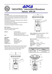
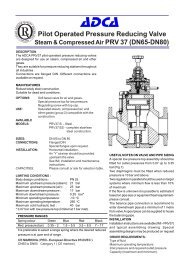
Float and Thermostatic Steam Traps<br />
<strong>FLT</strong> <strong>17</strong>( Carbon Steel Body-Cast Iron Cover DN1/2”-1” ; DN 15-DN25 )<br />
Description<br />
<strong>FLT</strong> <strong>17</strong> float and thermostatic (integral air vent) steam traps<br />
series are designed for all types of low and high pressure steam<br />
heating and process equipment.<br />
Typical applications include unit heaters,heat exchangers,<br />
driers,jacketed vessels and all the applications where continuous<br />
drainage is essential.<br />
Connections are female screwed or flanged for horizontal or<br />
vertical installation.<br />
Main Features<br />
Modulating discharge.<br />
Discharges condensate at steam temperature.<br />
Unaffected by sudden or wide load and pressure<br />
changes.<br />
Excellent air discharge (by thermostatic air vent).<br />
Options:<br />
Internal strainer (only on horizontal models).<br />
SLR - steam lock release .<br />
Equalizing plug and venting connection.<br />
Use :<br />
Saturated and superheated steam.<br />
AVAILABLE<br />
Models : <strong>FLT</strong> <strong>17</strong>-4.5 - <strong>FLT</strong> <strong>17</strong>-10 - <strong>FLT</strong> <strong>17</strong>-14 .<br />
Sizes :<br />
Connections :<br />
1/2", 3/4",1” - DN15,DN20,DN25.<br />
Female screwed ISO 7/1 Rp (BS21)<br />
Flanged DIN.Special flanges upon request.<br />
Installation : Standard horizontal installation -<br />
flow from right to left <strong>FLT</strong><strong>17</strong> (R-L)<br />
Upon request:<br />
-horizontal installation with the flow from left to right <strong>FLT</strong><strong>17</strong> (L-R)<br />
-vertical installation with the flow from top to bottom <strong>FLT</strong><strong>17</strong> (V)<br />
See IMI, installation and maintenance instructions.<br />
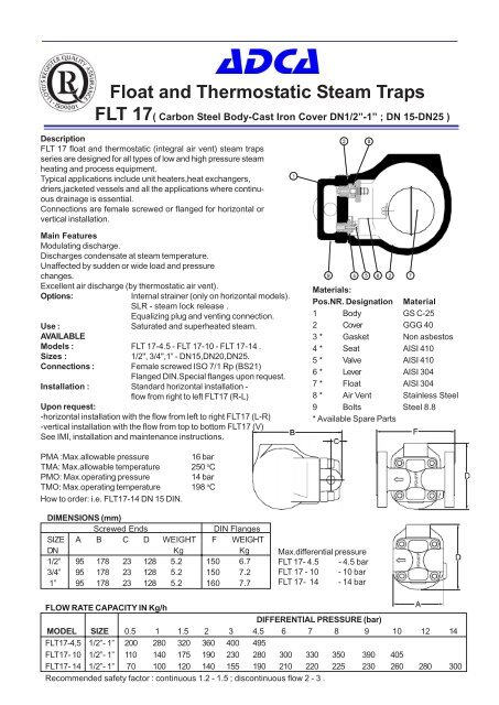
Materials:<br />
Pos.NR. Designation Material<br />
1 Body GS C-25<br />
2 Cover GGG 40<br />
3 * Gasket Non asbestos<br />
4 * Seat AISI 410<br />
5 * Valve AISI 410<br />
6 * Lever AISI 304<br />
7 * Float AISI 304<br />
8 * Air Vent Stainless Steel<br />
9 Bolts Steel 8.8<br />
* Available Spare Parts<br />
PMA :Max.allowable pressure<br />
TMA: Max.allowable temperature<br />
PMO: Max.operating pressure<br />
TMO: Max.operating temperature<br />
How to order: i.e. <strong>FLT</strong><strong>17</strong>-14 DN 15 DIN.<br />
16 bar<br />
250 o C<br />
14 bar<br />
198 o C<br />
DIMENSIONS (mm)<br />
Screwed Ends DIN Flanges<br />
SIZE A B C D WEIGHT F WEIGHT<br />
DN Kg Kg<br />
1/2” 95 <strong>17</strong>8 23 128 5.2 150 6.7<br />
3/4” 95 <strong>17</strong>8 23 128 5.2 150 7.2<br />
1” 95 <strong>17</strong>8 23 128 5.2 160 7.7<br />
Max.differential pressure<br />
<strong>FLT</strong> <strong>17</strong>- 4.5 - 4.5 bar<br />
<strong>FLT</strong> <strong>17</strong> - 10 - 10 bar<br />
<strong>FLT</strong> <strong>17</strong>- 14 - 14 bar<br />
FLOW RATE CAPACITY IN Kg/h<br />
DIFFERENTIAL PRESSURE (bar)<br />
MODEL SIZE 0.5 1 1.5 2 3 4.5 6 7 8 9 10 12 14<br />
<strong>FLT</strong><strong>17</strong>-4,5 1/2”- 1” 200 280 320 360 400 495<br />
<strong>FLT</strong><strong>17</strong>- 10 1/2”- 1” 110 140 <strong>17</strong>5 190 230 280 300 330 350 390 405<br />
<strong>FLT</strong><strong>17</strong>- 14 1/2”- 1” 70 100 120 140 155 190 210 220 225 230 260 280 300<br />
Recommended safety factor : continuous 1.2 - 1.5 ; discontinuous flow 2 - 3 .
abcde<br />
STEAM<br />
EQUIPMENT<br />
INSTALLATION AND MAINTENANCE INSTRUCTIONS<br />
<strong>FLT</strong><strong>17</strong><br />
FLOAT & THERMOSTATIC STEAM TRAPS<br />
GENERAL<br />
1.These instructions must be carefully read before any work involving products supplied by VALSTEAM<br />
<strong>ADCA</strong> ENGINEERING S.A. is undertaken.<br />
2.The installation procedure is a critical stage in a life of a steam trap and care should be taken to avoid<br />
damage to the trap or equipment.<br />
Warning !<br />
-At start up , the presence of small particles in the water (dirt,scale,weld splatters,etc) may cause an<br />
unperfect closure of the seat . If this occur, proceed to an accurate cleaning.<br />
-Do not touch the equipment without appropriate protection during working operation because it may<br />
conduct heat if the used fluid is at high temperature.<br />
-Before starting maintenance be sure that the equipment is not pressurized or hot .<br />
-The equipments must be used within the working temperature and pressure limits laid down for them,<br />
otherwise they may fail ( refer to nameplate and/or IS- Information Sheet).<br />
-Do not remove the nameplate attacched to the equipment.Serial number and other useful information is<br />
stamped on it.<br />
INSTALLATION<br />
1.Before to install remove plastic covers placed on flanges or connection ends. The equipment has<br />
an arrow or Inlet/Outlet designations.Be sure that it will be installed on the appropriate direction.<br />
2.Install the steam trap in the point of the system, where the condensate tends to collect.<br />
It must be installed with the float lever in horizontal plane, so that it rises and falls vertically.<br />
An <strong>ADCA</strong> strainer should be installed upstream of the trap.<br />
Limiting conditions <strong>FLT</strong> <strong>17</strong> :<br />
PMA :Max.allowable pressure 16 bar<br />
TMA: Max.allowable temperature 250 ºC<br />
PMO: Max.operating pressure 14 bar<br />
TMO: Max.operating temperature 198 ºC<br />
Max.differential pressure :<br />
<strong>FLT</strong> <strong>17</strong>-4.5 - 4.5 bar<br />
<strong>FLT</strong> <strong>17</strong> -10 - 10 bar<br />
<strong>FLT</strong> <strong>17</strong>- 14 - 14 bar<br />
MAINTENANCE<br />
1.We recommend that the float steam traps are serviced as necessary.Steam traps should be checked<br />
periodically (at least yearly), to verify that they are operating correctly and to clean the internal parts and<br />
screen (if any).<br />
2.When reassembling make sure that all gasket faces are clean and always use a new gasket. Tighten<br />
cover bolts uniformly in a diagonal sequence.<br />
3.For further information refer to the relevant <strong>FLT</strong><strong>17</strong> brochure or consult our Sales Office.<br />
CE Marking :<br />
This product have been designed for use on steam and water<br />
wich are in Group 2 of the PED-European Pressure Equipment<br />
Directive 97/23/EC and it comply with those requirements.<br />
The product fall within category SEP and must not be CE marked.<br />
GROUP 2 GASES CATEGORIES<br />
MODEL SIZES Category<br />
<strong>FLT</strong> <strong>17</strong> ALL SEP<br />
<strong>FLT</strong><strong>17</strong>HC DN 25 SEP<br />
LOSS OF GUARANTEE : Total or partial disregard of above instructions involves loss of any right to guarantee.<br />
VALSTEAM <strong>ADCA</strong> ENGINEERING SA - Trav.da Douroana -2419-006 Regueira de Pontes-Leria-Portugal<br />
IMI 1.335 E 06.06
STEAM<br />
EQUIPMENT<br />
PARTS LIST FOR <strong>FLT</strong> <strong>17</strong>- STEAM TRAPS DN 1/2”- 1”, DN15-DN25<br />
Code Designation SizeTrap Pos.Nr. Qty.<br />
A.92.1502.015 Valve,seat,float&gasket D.P.4,5bar DN1/2”-1” 3,4,5,6,7 1Set<br />
A.92.1503.015 Valve,seat,float&gasket D.P.10 bar DN1/2”-1” 3,4,5,6,7 1Set<br />
A.92.1504.015 Valve,seat,float&gasket D.P.14 bar DN1/2”-1” 3,4,5,6,7 1Set<br />
A.92.1502.115 Float & gasket DN1/2”-1” 3,7 1Set<br />
A.92.1502.215 Air vent & gasket DN1/2”-1” 3,8 1Set<br />
3 8<br />
Recommended tightening torques <strong>FLT</strong><strong>17</strong> DN 1/2”-1”, DN15-DN25<br />
Pos.Nr. Size Nm<br />
4 1/2”-1” 50-55<br />
8 1/2”-1” 50-55<br />
9 1/2”-1” 40-45<br />
Remarks: Tighten cover bolts uniformly.<br />
1<br />
PARTS LIST FOR <strong>FLT</strong> <strong>17</strong>HC STEAM TRAPS DN 1”, DN25<br />
Code Designation SizeTrap Pos.Nr. Qty.<br />
A.92.1502.025 Valve,seat,float&gasket D.P.4,5bar DN1” 3,4,5,6,7 1Set<br />
A.92.1503.025 Valve,seat,float&gasket D.P.10 bar DN1” 3,4,5,6,7 1Set<br />
A.92.1504.025 Valve,seat,float&gasket D.P.14 bar DN1” 3,4,5,6,7 1Set<br />
A.92.1502.125 Float & gasket DN1” 3,7 1Set<br />
A.92.1502.225 Air vent& gasket DN1” 3,8 1Set<br />
9 4 5 6 2<br />
7<br />
Recommended tightening torques <strong>FLT</strong><strong>17</strong>HC DN 1”, DN25<br />
Pos.Nr. Size Nm<br />
4 1” 50-55<br />
8 1” 50-55<br />
9 1” 40-45<br />
Remarks: Tighten cover bolts uniformly.<br />
9<br />
8<br />
PARTS LIST FOR <strong>FLT</strong> <strong>17</strong> STEAM TRAPS DN DN40-DN50<br />
Code Designation SizeTrap Pos.Nr. Qty.<br />
A.92.1502.040 Valve,seat,float&gasket D.P.4,5bar DN11/2”-2” 3,4,5,6,7 1Set<br />
A.92.1503.040 Valve,seat,float&gasket D.P.10 bar DN11/2”-2” 3,4,5,6,7 1Set<br />
A.92.1504.040 Valve,seat,float&gasket D.P.14 bar DN11/2”-2” 3,4,5,6,7 1Set<br />
A.92.1502.140 Float & gasket DN11/2”-2” 3,7 1Set<br />
A.92.1502.240 Air vent& gasket DN11/2”-2” 3,8 1Set<br />
1<br />
3 4 5 10 6 2 7<br />
Recommended tightening torques <strong>FLT</strong><strong>17</strong> DN40-DN50<br />
Pos.Nr. Size Nm<br />
4 11/2”-2” 10-15 (4xM6)<br />
8 11/2” -2” 50-55<br />
9 11/2”-2” 80-85<br />
Remarks: Tighten cover bolts uniformly.<br />
IMI 1.335 E 06.06