The Memory Hierarchy
The Memory Hierarchy
The Memory Hierarchy

Create successful ePaper yourself
Turn your PDF publications into a flip-book with our unique Google optimized e-Paper software.
<strong>Memory</strong> Architecture<br />
<strong>Memory</strong> Architecture<br />
Chapter Six<br />
6.1 Chapter Overview<br />
This chapter discusses the memory hierarchy – the different types and performance levels of memory<br />
found on a typical 80x86 computer system. Many programmers tend to view memory as this big nebulous<br />
block of storage that holds values for future use. From a semantic point of view, this is a reasonable view.<br />
However, from a performance point of view there are many different kinds of memory and using the wrong<br />
one or using one form improperly can have a dramatically negative impact on the performance of a program.<br />
This chapter discusses the memory hierarchy and how to best use it within your programs.<br />
6.2 <strong>The</strong> <strong>Memory</strong> <strong>Hierarchy</strong><br />
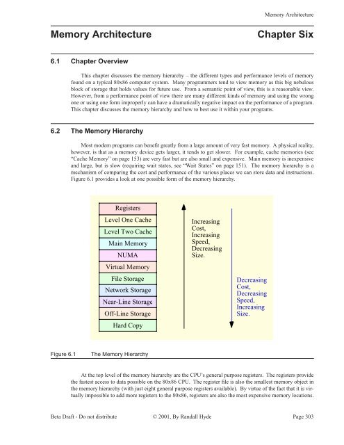
Most modern programs can benefit greatly from a large amount of very fast memory. A physical reality,<br />
however, is that as a memory device gets larger, it tends to get slower. For example, cache memories (see<br />
“Cache <strong>Memory</strong>” on page 153) are very fast but are also small and expensive. Main memory is inexpensive<br />
and large, but is slow (requiring wait states, see “Wait States” on page 151). <strong>The</strong> memory hierarchy is a<br />
mechanism of comparing the cost and performance of the various places we can store data and instructions.<br />
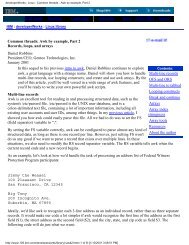
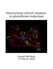
Figure 6.1 provides a look at one possible form of the memory hierarchy.<br />
Registers<br />
Level One Cache<br />
Level Two Cache<br />
Main <strong>Memory</strong><br />
NUMA<br />
Virtual <strong>Memory</strong><br />
File Storage<br />
Network Storage<br />
Near-Line Storage<br />
Off-Line Storage<br />
Hard Copy<br />
Increasing<br />
Cost,<br />
Increasing<br />
Speed,<br />
Decreasing<br />
Size.<br />
Decreasing<br />
Cost,<br />
Decreasing<br />
Speed,<br />
Increasing<br />
Size.<br />
Figure 6.1<br />
<strong>The</strong> <strong>Memory</strong> <strong>Hierarchy</strong><br />
At the top level of the memory hierarchy are the CPU’s general purpose registers. <strong>The</strong> registers provide<br />
the fastest access to data possible on the 80x86 CPU. <strong>The</strong> register file is also the smallest memory object in<br />
the memory hierarchy (with just eight general purpose registers available). By virtue of the fact that it is virtually<br />
impossible to add more registers to the 80x86, registers are also the most expensive memory locations.<br />
Beta Draft - Do not distribute © 2001, By Randall Hyde Page 303
Chapter Six<br />
Volume Two<br />
Note that we can include FPU, MMX, SIMD, and other CPU registers in this class as well. <strong>The</strong>se additional<br />
registers do not change the fact that there are a very limited number of registers and the cost per byte is quite<br />
high (figuring the cost of the CPU divided by the number of bytes of register available).<br />
Working our way down, the Level One Cache system is the next highest performance subsystem in the<br />
memory hierarchy. On the 80x86 CPUs, the Level One Cache is provided on-chip by Intel and cannot be<br />
expanded. <strong>The</strong> size is usually quite small (typically between 4Kbytes and 32Kbytes), though much larger<br />
than the registers available on the CPU chip. Although the Level One Cache size is fixed on the CPU and<br />
you cannot expand it, the cost per byte of cache memory is much lower than that of the registers because the<br />
cache contains far more storage than is available in all the combined registers.<br />
<strong>The</strong> Level Two Cache is present on some CPUs, on other CPUs it is the system designer’s task to incorporate<br />
this cache (if it is present at all). For example, most Pentium II, III, and IV CPUs have a level two<br />
cache as part of the CPU package, but many of Intel’s Celeron chips do not 1 . <strong>The</strong> Level Two Cache is generally<br />
much larger than the level one cache (e.g., 256 or 512KBytes versus 16 Kilobytes). On CPUs where<br />
Intel includes the Level Two Cache as part of the CPU package, the cache is not expandable. It is still lower<br />
cost than the Level One Cache because we amortize the cost of the CPU across all the bytes in the Level Two<br />
Cache. On systems where the Level Two Cache is external, many system designers let the end user select<br />
the cache size and upgrade the size. For economic reasons, external caches are actually more expensive than<br />
caches that are part of the CPU package, but the cost per bit at the transistor level is still equivalent to the<br />
in-package caches.<br />
Below the Level Two Cache system in the memory hierarchy falls the main memory subsystem. This is<br />
the general-purpose, relatively low-cost memory found in most computer systems. Typically, this is DRAM<br />
or some similar inexpensive memory technology.<br />
Below main memory is the NUMA category. NUMA, which stands for NonUniform <strong>Memory</strong> Access is<br />
a bit of a misnomer here. NUMA means that different types of memory have different access times. <strong>The</strong>refore,<br />
the term NUMA is fairly descriptive of the entire memory hierarchy. In Figure 6.1a, however, we’ll use<br />
the term NUMA to describe blocks of memory that are electronically similar to main memory but for one<br />
reason or another operate significantly slower than main memory. A good example is the memory on a video<br />
display card. Access to memory on video display cards is often much slower than access to main memory.<br />
Other peripheral devices that provide a block of shared memory between the CPU and the peripheral probably<br />
have similar access times as this video card example. Another example of NUMA includes certain<br />
slower memory technologies like Flash <strong>Memory</strong> that have significant slower access and transfers times than<br />
standard semiconductor RAM. We’ll use the term NUMA in this chapter to describe these blocks of memory<br />
that look like main memory but run at slower speeds.<br />
Most modern computer systems implement a Virtual <strong>Memory</strong> scheme that lets them simulate main<br />
memory using storage on a disk drive. While disks are significantly slower than main memory, the cost per<br />
bit is also significantly lower. <strong>The</strong>refore, it is far less expensive (by three orders of magnitude) to keep some<br />
data on magnetic storage rather than in main memory. A Virtual <strong>Memory</strong> subsystem is responsible for transparently<br />
copying data between the disk and main memory as needed by a program.<br />
File Storage also uses disk media to store program data. However, it is the program’s responsibility to<br />
store and retrieve file data. In many instances, this is a bit slower than using Virtual <strong>Memory</strong>, hence the<br />
lower position in the memory hierarchy 2 .<br />
Below File Storage in the memory hierarchy comes Network Storage. At this level a program is keeping<br />
data on a different system that connects the program’s system via a network. With Network Storage you<br />
can implement Virtual <strong>Memory</strong>, File Storage, and a system known as Distributed Shared <strong>Memory</strong> (where<br />
processes running on different computer systems share data in a common block of memory and communicate<br />
changes to that block across the network).<br />
Virtual <strong>Memory</strong>, File Storage, and Network Storage are examples of so-called on-line memory subsystems.<br />
<strong>Memory</strong> access via these mechanism is slower than main memory access, but when a program<br />
1. Note, by the way, that the level two cache on the Pentium CPUs is typically not on the same chip as the CPU. Instead, Intel<br />
packages a separate chip inside the box housing the Pentium CPU and wires this second chip (containing the level two cache)<br />
directly to the Pentium CPU inside the package.<br />
2. Note, however, that in some degenerate cases Virtual <strong>Memory</strong> can be much slower than file access.<br />
Page 304 © 2001, By Randall Hyde Beta Draft - Do not distribute
<strong>Memory</strong> Architecture<br />
requests data from one of these memory devices, the device is ready and able to respond to the request as<br />
quickly as is physically possible. This is not true for the remaining levels in the memory hierarchy.<br />
<strong>The</strong> Near-Line and Off-Line Storage subsystems are not immediately ready to respond to a program’s<br />
request for data. An Off-Line Storage system keeps its data in electronic form (usually magnetic or optical)<br />
but on media that is not (necessarily) connected to the computer system while the program that needs the<br />
data is running. Examples of Off-Line Storage include magnetic tapes, disk cartridges, optical disks, and<br />
floppy diskettes. When a program needs data from an off-line medium, the program must stop and wait for a<br />
someone or something to mount the appropriate media on the computer system. This delay can be quite<br />
long (perhaps the computer operator decided to take a coffee break?). Near-Line Storage uses the same<br />
media as Off-Line Storage, the difference is that the system holds the media in a special robotic jukebox<br />
device that can automatically mount the desired media when some program requests it. Tapes and removable<br />
media are among the most inexpensive electronic data storage formats available. Hence, these media<br />
are great for storing large amounts of data for long time periods.<br />
Hard Copy storage is simply a print-out (in one form or another) of some data. If a program requests<br />
some data and that data is present only in hard copy form, someone will have to manually enter the data into<br />
the computer. Paper (or other hard copy media) is probably the least expensive form of memory, at least for<br />
certain data types.<br />
6.3 How the <strong>Memory</strong> <strong>Hierarchy</strong> Operates<br />
<strong>The</strong> whole point of the memory hierarchy is to allow reasonably fast access to a large amount of memory.<br />
If only a little memory was necessary, we’d use fast static RAM (i.e., the stuff they make cache memory<br />
out of) for everything. If speed wasn’t necessary, we’d just use low-cost dynamic RAM for everything. <strong>The</strong><br />
whole idea of the memory hierarchy is that we can take advantage of the principle of locality of reference<br />
(see “Cache <strong>Memory</strong>” on page 153) to move often-referenced data into fast memory and leave less-used data<br />
in slower memory. Unfortunately, the selection of often-used versus lesser-used data varies over the execution<br />
of any given program. <strong>The</strong>refore, we cannot simply place our data at various levels in the memory hierarchy<br />
and leave the data alone throughout the execution of the program. Instead, the memory subsystems<br />
need to be able to move data between themselves dynamically to adjust for changes in locality of reference<br />
during the program’s execution.<br />
Moving data between the registers and the rest of the memory hierarchy is strictly a program function.<br />
<strong>The</strong> program, of course, loads data into registers and stores register data into memory using instructions like<br />
MOV. It is strictly the programmer’s or compiler’s responsibility to select an instruction sequence that keeps<br />
heavily referenced data in the registers as long as possible.<br />
<strong>The</strong> program is largely unaware of the memory hierarchy. In fact, the program only explicitly controls<br />
access to main memory and those components of the memory hierarchy at the file storage level and below<br />
(since manipulating files is a program-specific operation). In particular, cache access and virtual memory<br />
operation are generally transparent to the program. That is, access to these levels of the memory hierarchy<br />
usually take place without any intervention on the program’s part. <strong>The</strong> program just accesses main memory<br />
and the hardware (and operating system) take care of the rest.<br />
Of course, if the program really accessed main memory on each access, the program would run quite<br />
slowly since modern DRAM main memory subsystems are much slower than the CPU. <strong>The</strong> job of the cache<br />
memory subsystems (and the cache controller) is to move data between main memory and the cache so that<br />
the CPU can quickly access data in the cache. Likewise, if data is not available in main memory, but is available<br />
in slower virtual memory, the virtual memory subsystem is responsible for moving the data from hard<br />
disk to main memory (and then the caching subsystem may move the data from main memory to cache for<br />
even faster access by the CPU).<br />
With few exceptions, most transparent memory subsystem accesses always take place between one level<br />
of the memory hierarchy and the level immediately below or above it. For example, the CPU rarely accesses<br />
main memory directly. Instead, when the CPU requests data from memory, the Level One Cache subsystem<br />
takes over. If the requested data is in the cache, then the Level One Cache subsystem returns the data and<br />
that’s the end of the memory access. On the other hand if the data is not present in the level one cache, then<br />
Beta Draft - Do not distribute © 2001, By Randall Hyde Page 305
Chapter Six<br />
Volume Two<br />
it passes the request on down to the Level Two Cache subsystem. If the Level Two Cache subsystem has the<br />
data, it returns this data to the Level One Cache, which then returns the data to the CPU. Note that requests<br />
for this same data in the near future will come from the Level One Cache rather than the Level Two Cache<br />
since the Level One Cache now has a copy of the data.<br />
If neither the Level One nor Level Two Cache subsystems have a copy of the data, then the memory subsystem<br />
goes to main memory to get the data. If found in main memory, then the memory subsystems copy<br />
this data to the Level Two Cache which passes it to the Level One Cache which gives it to the CPU. Once<br />
again, the data is now in the Level One Cache, so any references to this data in the near future will come<br />
from the Level One Cache.<br />
If the data is not present in main memory, but is present in Virtual <strong>Memory</strong> on some storage device, the<br />
operating system takes over, reads the data from disk (or other devices, such as a network storage server) and<br />
places this data in main memory. Main memory then passes this data through the caches to the CPU.<br />
Because of locality of reference, the largest percentage of memory accesses take place in the Level One<br />
Cache system. <strong>The</strong> next largest percentage of accesses occur in the Level Two Cache subsystems. <strong>The</strong> most<br />
infrequent accesses take place in Virtual <strong>Memory</strong>.<br />
6.4 Relative Performance of <strong>Memory</strong> Subsystems<br />
If you take another look at Figure 6.1 you’ll notice that the speed of the various levels increases at the<br />
higher levels of the memory hierarchy. A good question to ask, and one we’ll hope to answer in this section,<br />
is "how much faster is each successive level in the memory hierarchy?" It actually ranges from "almost no<br />
difference" to "four orders of magnitude" as you’ll seem momentarily.<br />
Registers are, unquestionably, the best place to store data you need to access quickly. Accessing a register<br />
never requires any extra time 3 . Further, instructions that access data can almost always access that data in<br />
a register. Such instructions already encode the register "address" as part of the MOD-REG-R/M byte (see<br />
“Encoding Instruction Operands” on page 290). <strong>The</strong>refore, it never takes any extra bits in an instruction to use a<br />
register. Instructions that access memory often require extra bytes (i.e., displacement bytes) as part of the<br />
instruction encoding. This makes the instruction longer which means fewer of them can sit in the cache or in<br />
a prefetch queue. Hence, the program may run slower if it uses memory operands more often than register<br />
operands simply due to the instruction size difference.<br />
If you read Intel’s instruction timing tables, you’ll see that they claim that an instruction like<br />
"mov( someVar, ecx );" is supposed to run as fast as an instruction of the form "mov( ebx, ecx );" However,<br />
if you read the fine print, you’ll find that they make several assumptions about the former instruction. First,<br />
they assume that someVar’s value is present in the level one cache memory. If it is not, then the cache controller<br />
needs to look in the level two cache, in main memory, or worse, on disk in the virtual memory subsystem.<br />
All of a sudden, this instruction that should execute in one cycle (e.g., one nanosecond on a one<br />
gigahertz processor) requires several milliseconds to execution. That’s over six orders of magnitude difference,<br />
if you’re counting. Now granted, locality of reference suggests that future accesses to this variable will<br />
take place in one cycle. However, if you access someVar’s value one million times immediately thereafter,<br />
the average access time of each instruction will be two cycles because of the large amount of time needed to<br />
access someVar the very first time (when it was on a disk in the virtual memory system). Now granted, the<br />
likelihood that some variable will be on disk in the virtual memory subsystem is quite low. But there is a<br />
three orders of magnitude difference in performance between the level one cache subsystem and the main<br />
memory subsystem. So if the program has to bring in the data from main memory, 999 accesses later you’re<br />
still paying an average cost of two cycles for the instruction that Intel’s documentation claims should execute<br />
in one cycle. Note that register accesses never suffer from this problem. Hence, register accesses are much<br />
faster.<br />
3. Okay, strictly speaking this is not true. However, we’ll ignore data hazards in this discussion and assume that the programmer<br />
or compiler has scheduled their instructions properly to avoid pipeline stalls due to data hazards with register data.<br />
Page 306 © 2001, By Randall Hyde Beta Draft - Do not distribute
<strong>Memory</strong> Architecture<br />
<strong>The</strong> difference between the level one and level two cache systems is not so dramatic. Usually, a level<br />
two caching subsystem introduces between one and eight wait states (see “Wait States” on page 151). <strong>The</strong><br />
difference is usually much greater, though, if the secondary cache is not packaged together with the CPU.<br />
On a one gigahertz processor the level one cache must respond within one nanosecond if the cache operates<br />
with zero wait states (note that some processors actually introduce wait states in accesses to the level<br />
one cache, but system designers try not to do this). Accessing data in the level two cache is always slower<br />
than in the level one cache and there is always the equivalent of at least one wait state, perhaps more, when<br />
accessing data in the level two cache. <strong>The</strong> reason is quite simple – it takes the CPU time to determine that<br />
the data it is seeking is not in the L1 (level one) cache; by the time it determines that the data is not present,<br />
the memory access cycle is nearly complete and there is no time to access the data in the L2 (level two)<br />
cache.<br />
It may also be that the L2 cache is slower than the L1 cache. This is usually done in order to make the<br />
L2 cache less expensive. Also, larger memory subsystems tend to be slower than smaller ones, and L2<br />
caches are usually 16 to 64 times larger than the L1 cache, hence they are usually slower as well. Finally,<br />
because L2 caches are not usually on the same silicon chip as the CPU, there are some delays associated<br />
with getting data in and out of the cache. All this adds up to additional wait states when accessing data in the<br />
L2 cache. As noted above, the L2 cache can be as much as an order of magnitude slower than the L1 cache.<br />
Another difference between the L1 and L2 caches is the amount of data the system fetches when there is<br />
an L1 cache miss. When the CPU fetches data from the L1 cache, it generally fetches (or writes) only the<br />
data requested. If you execute a "mov( al, memory);" instruction, the CPU writes only a single byte to the<br />
cache. Likewise, if you execute "mov( mem32, eax );" then the CPU reads 32 bits from the L1 cache.<br />
Access to memory subsystems below the L1 cache, however, do not work in small chucks like this. Usually,<br />
memory subsystems read blocks (or cache lines) of data whenever accessing lower levels of the memory<br />
hierarchy. For example, if you execute the "mov( mem32, eax );" instruction and mem32’s value is not in the<br />
L1 cache, the cache controller doesn’t simply read mem32’s value from the L2 cache (assuming it’s present<br />
there). Instead, the cache controller will actually read a block of bytes (generally 16, 32, or 64 bytes, this<br />
depends on the particular processor) from the lower memory levels. <strong>The</strong> hope is that spatial locality exists<br />
and reading a block of bytes will speed up accesses to adjacent objects in memory 4 . <strong>The</strong> bad news, however,<br />
is that the "mov( mem32, eax );" instruction doesn’t complete until the L1 cache reads the entire cache line<br />
(of 16, 32, 64, etc., bytes) from the L2 cache. Although the program may amortize the cost of reading this<br />
block of bytes over future accesses to adjacent memory locations, there is a large passage of time between<br />
the request for mem32 and the actual completion of the "mov( mem32, eax );" instruction. This excess time<br />
is known as latency. As noted, the hope is that extra time will be worth the cost when future accesses to adjacent<br />
memory locations occur; however, if the program does not access memory objects adjacent to mem32,<br />
this latency is lost time.<br />
A similar performance gulf separates the L2 cache and main memory. Main memory is typically an<br />
order of magnitude slower than the L2 cache. Again the L2 cache reads data from main memory in blocks<br />
(cache lines) to speed up access to adjacent memory elements.<br />
<strong>The</strong>re is a three to four order of magnitude difference in performance between standard DRAM and disk<br />
storage. To overcome this difference, there is usually a two to three orders of magnitude difference in size<br />
between the L2 cache and the main memory. In other words, the idea is "if the access time difference<br />
between main memory and virtual memory is two orders of magnitude greater than the difference between<br />
the L2 cache and main memory, then we’d better make sure we have two orders of magnitude more main<br />
memory than we have L2 cache." This keeps the performance loss to a reasonable level since we access virtual<br />
memory on disk two orders of magnitude less often.<br />
We will not consider the performance of the other memory hierarchy subsystems since they are more or<br />
less under programmer control (their access is not automatic by the CPU or operating system). Hence, very<br />
little can be said about how frequently a program will access them.<br />
4. Note that reading a block of n bytes is much faster than n reads of one byte. So this scheme is many times faster if spatial<br />
locality does occur in the program. For information about spatial locality, see “Cache <strong>Memory</strong>” on page 153.<br />
Beta Draft - Do not distribute © 2001, By Randall Hyde Page 307
Chapter Six<br />
Volume Two<br />
6.5 Cache Architecture<br />
Up to this point, cache has been this magical place that automatically stores data when we need it, perhaps<br />
fetching new data as the CPU requires it. However, a good question is "how exactly does the cache do<br />
this?" Another might be "what happens when the cache is full and the CPU is requesting additional data not<br />
in the cache?" In this section, we’ll take a look at the internal cache organization and try to answer these<br />
questions along with a few others.<br />
<strong>The</strong> basic idea behind a cache is that a program only access a small amount of data at a given time. If<br />
the cache is the same size as the typical amount of data the program access at any one given time, then we<br />
can put that data into the cache and access most of the data at a very high speed. Unfortunately, the data<br />
rarely sits in contiguous memory locations; usually, there’s a few bytes here, a few bytes there, and some<br />
bytes somewhere else. In general, the data is spread out all over the address space. <strong>The</strong>refore, the cache<br />
design has got to accommodate the fact that it must map data objects at widely varying addresses in memory.<br />
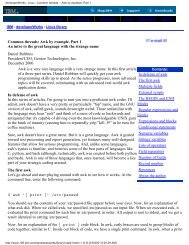
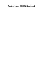
As noted in the previous section, cache memory is not organized as a group of bytes. Instead, cache<br />
organization is usually in blocks of cache lines with each line containing some number of bytes (typically a<br />
small number that is a power of two like 16, 32, or 64), see Figure 6.2.<br />
An 8KByte cache is often organized as a set<br />
of 512 lines of 16 bytes each.<br />
Figure 6.2<br />
Possible Organization of an 8 Kilobyte Cache<br />
<strong>The</strong> idea of a cache system is that we can attach a different (non-contiguous) address to each of the<br />
cache lines. So cache line #0 might correspond to addresses $10000..$1000F and cache line #1 might correspond<br />
to addresses $21400..$2140F. Generally, if a cache line is n bytes long (n is usually some power of<br />
two) then that cache line will hold n bytes from main memory that fall on an n-byte boundary. In this example,<br />
the cache lines are 16 bytes long, so a cache line holds blocks of 16 bytes whose addresses fall on<br />
16-byte boundaries in main memory (i.e., the L.O. four bits of the address of the first byte in the cache line<br />
are always zero).<br />
When the cache controller reads a cache line from a lower level in the memory hierarchy, a good question<br />
is "where does the data go in the cache?" <strong>The</strong> most flexible cache system is the fully associative cache.<br />
In a fully associative cache subsystem, the caching controller can place a block of bytes in any one of the<br />
cache lines present in the cache memory. While this is a very flexible system, the flexibility is not without<br />
cost. <strong>The</strong> extra circuitry to achieve full associativity is expensive and, worse, can slow down the memory<br />
subsystem. Most L1 and L2 caches are not fully associative for this reason.<br />
At the other extreme is the direct mapped cache (also known as the one-way set associative cache). In a<br />
direct mapped cache, a block of main memory is always loaded into the same cache line in the cache. Generally,<br />
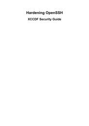
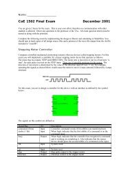
some number of bits in the main memory address select the cache line. For example, Figure 6.3<br />
shows how the cache controller could select a cache line for an 8 Kilobyte cache with 16-byte cache lines<br />
and a 32-bit main memory address. Since there are 512 cache lines, this example uses bits four through<br />
twelve to select one of the cache lines (bits zero through three select a particular byte within the 16-byte<br />
cache line). <strong>The</strong> direct-mapped cache scheme is very easy to implement. Extracting nine (or some other<br />
Page 308 © 2001, By Randall Hyde Beta Draft - Do not distribute
<strong>Memory</strong> Architecture<br />
number of) bits from the address and using this as an index into the array of cache lines is trivial and fast.<br />
However, direct-mapped caches to suffer from some other problems.<br />
31<br />
13<br />
12<br />
4<br />
3<br />
0<br />
32-bit physical address<br />
Nine bits (bits 4..12)<br />
provide an index to<br />
select one of the 512<br />
different cache lines<br />
in the cache.<br />
An 8KByte cache<br />
organized as a set<br />
of 512 lines of 16<br />
bytes each.<br />
Figure 6.3<br />
Selecting a Cache Line in a Direct-mapped Cache<br />
Perhaps the biggest problem with a direct-mapped cache is that it may not make effective use of all the<br />
cache memory. For example, the cache scheme in Figure 6.3 maps address zero to cache line #0. It also<br />
maps address $2000 (8K), $4000 (16K), $6000 (24K), $8000 (32K), and, in fact, it maps every address that<br />
is an even multiple of eight kilobytes to cache line #0. This means that if a program is constantly accessing<br />
data at addresses that are even multiples of 8K and not accessing any other locations, the system will only<br />
use cache line #0, leaving all the other cache lines unused. Each time the CPU requests data at an address<br />
that is not at an address within cache line #0, the CPU will have to go down to a lower level in the memory<br />
hierarchy to access the data. In this pathological case, the cache is effectively limited to the size of one<br />
cache line. Had we used a fully associative cache organization, each access (up to 512 cache lines’ worth)<br />
could have their own cache line, thus improving performance.<br />
If a fully associative cache organization is too complex, expensive, and slow to implement, but a<br />
direct-mapped cache organization isn’t as good as we’d like, one might ask if there is a compromise that<br />
gives us more capability that a direct-mapped approach without all the complexity of a fully associative<br />
cache. <strong>The</strong> answer is yes, we can create an n-way set associative cache which is a compromise between<br />
these two extremes. <strong>The</strong> idea here is to break up the cache into sets of cache lines. <strong>The</strong> CPU selects a particular<br />
set using some subset of the address bits, just as for direct-mapping. Within each set there are n cache<br />
lines. <strong>The</strong> caching controller uses a fully associative mapping algorithm to select one of the n cache lines<br />
within the set.<br />
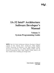
As an example, an 8 kilobyte two-way set associative cache subsystem with 16-byte cache lines organizes<br />
the cache as a set of 256 sets with each set containing two cache lines ("two-way" means each set contains<br />
two cache lines). Eight bits from the memory address select one of these 256 different sets. <strong>The</strong>n the<br />
cache controller can map the block of bytes to either cache line within the set (see Figure 6.4). <strong>The</strong> advantage<br />
of a two-way set associative cache over a direct mapped cache is that you can have two accesses on 8<br />
Kilobyte boundaries (using the current example) and still get different cache lines for both accesses. However,<br />
once you attempt to access a third memory location at an address that is an even multiple of eight kilobytes<br />
you will have a conflict.<br />
Beta Draft - Do not distribute © 2001, By Randall Hyde Page 309
Chapter Six<br />
Volume Two<br />
31<br />
12<br />
11<br />
4<br />
3<br />
0<br />
32-bit physical address<br />
Eight bits (bits 4..11)<br />
provide an index to<br />
select one of the 256<br />
different sets of cache<br />
lines in the cache.<br />
<strong>The</strong> cache controller<br />
chooses one of<br />
the two different<br />
cache lines within<br />
the set.<br />
Figure 6.4<br />
A Two-Way Set Associative Cache<br />
A two-way set associative cache is much better than a direct-mapped cache and considerably less complex<br />
than a fully associative cache. However, if you’re still getting too many conflicts, you might consider<br />
using a four-way set associative cache. A four-way set associative cache puts four associative cache lines in<br />
each block. In the current 8K cache example, a four-way set associative example would have 128 sets with<br />
each set containing four cache lines. This would allow up to four accesses to an address that is an even multiple<br />
of eight kilobytes before a conflict would occur.<br />
Obviously, we can create an arbitrary m-way set associative cache (well, m does have to be a power of<br />
two). However, if m is equal to n, where n is the number of cache lines, then you’ve got a fully associative<br />
cache with all the attendant problems (complexity and speed). Most cache designs are direct-mapped,<br />
two-way set associative, or four-way set associative. <strong>The</strong> 80x86 family CPUs use all three (depending on<br />
the CPU and cache).<br />
Although this section has made direct-mapped cache look bad, they are, in fact, very effective for many<br />
types of data. In particular, they are very good for data that you access in a sequential rather than random<br />
fashion. Since the CPU typically executes instructions in a sequential fashion, instructions are a good thing<br />
to put into a direct-mapped cache. Data access is probably a bit more random access, so a two-way or<br />
four-way set associative cache probably makes a better choice.<br />
Because access to data and instructions is different, many CPU designers will use separate caches for<br />
instructions and data. For example, the CPU designer could choose to implement an 8K instruction cache<br />
and an 8K data cache rather than a 16K unified cache. <strong>The</strong> advantage is that the CPU designer could choose<br />
a more appropriate caching scheme for instructions versus data. <strong>The</strong> drawback is that the two caches are<br />
now each half the size of a unified cache and you may get fewer cache misses from a unified cache. <strong>The</strong><br />
choice of an appropriate cache organization is a difficult one and can only be made after analyzing lots of<br />
running programs on the target processor. How to choose an appropriate cache format is beyond the scope<br />
of this text, just be aware that it’s not an easy choice you can make by reading some textbook.<br />
Thus far, we’ve answered the question "where do we put a block of data when we read it into the<br />
cache?" An equally important question we ignored until now is "what happens if a cache line isn’t available<br />
when we need to read data from memory?" Clearly, if all the lines in a set of cache lines contain data, we’re<br />
going to have to replace one of these lines with the new data. <strong>The</strong> question is, "how do we choose the cache<br />
line to replace?"<br />
For a direct-mapped (one-way set associative) cache architecture, the answer is trivial. We replace<br />
exactly the block that the memory data maps to in the cache. <strong>The</strong> cache controller replaces whatever data<br />
Page 310 © 2001, By Randall Hyde Beta Draft - Do not distribute
<strong>Memory</strong> Architecture<br />
was formerly in the cache line with the new data. Any reference to the old data will result in a cache miss<br />
and the cache controller will have to bring that data into the cache replacing whatever data is in that block at<br />
that time.<br />
For a two-way set associative cache, the replacement algorithm is a bit more complex. Whenever the<br />
CPU references a memory location, the cache controller uses some number of the address bits to select the<br />
set that should contain the cache line. Using some fancy circuity, the caching controller determines if the<br />
data is already present in one of the two cache lines in the set. If not, then the CPU has to bring the data in<br />
from memory. Since the main memory data can go into either cache line, somehow the controller has to<br />
pick one or the other. If either (or both) cache lines are currently unused, the selection is trivial: pick an<br />
unused cache line. If both cache lines are currently in use, then the cache controller must pick one of the<br />
cache lines and replace its data with the new data. Ideally, we’d like to keep the cache line that will be referenced<br />
first (that is, we want to replace the one whose next reference is later in time). Unfortunately, neither<br />
the cache controller nor the CPU is omniscient, they cannot predict which is the best one to replace.<br />
However, remember the principle of temporal locality (see “Cache <strong>Memory</strong>” on page 153): if a memory<br />
location has been referenced recently, it is likely to be referenced again in the very near future. A corollary<br />
to this is "if a memory location has not been accessed in a while, it is likely to be a long time before the CPU<br />
accesses it again." <strong>The</strong>refore, a good replacement policy that many caching controllers use is the "least<br />
recently used" or LRU algorithm. <strong>The</strong> idea is to pick the cache line that was not most frequently accessed<br />
and replace that cache line with the new data. An LRU policy is fairly easy to implement in a two-way set<br />
associative cache system. All you need is a bit that is set to zero whenever the CPU accessing one cache line<br />
and set it to one when you access the other cache line. This bit will indicate which cache line to replace<br />
when a replacement is necessary. For four-way (and greater) set associative caches, maintaining the LRU<br />
information is a bit more difficult, which is one of the reasons the circuitry for such caches is more complex.<br />
Other possible replacement policies include First-in, First-out 5 (FIFO) and random. <strong>The</strong>se are easier to<br />
implement than LRU, but they have their own problems.<br />
<strong>The</strong> replacement policies for four-way and n-way set associative caches are roughly the same as for<br />
two-way set associative caches. <strong>The</strong> major difference is in the complexity of the circuit needed to implement<br />
the replacement policy (see the comments on LRU in the previous paragraph).<br />
Another problem we’ve overlooked in this discussion on caches is "what happens when the CPU writes<br />
data to memory?" <strong>The</strong> simple answer is trivial, the CPU writes the data to the cache. However, what happens<br />
when the cache line containing this data is replaced by incoming data? If the contents of the cache line<br />
is not written back to main memory, then the data that was written will be lost. <strong>The</strong> next time the CPU reads<br />
that data, it will fetch the original data values from main memory and the value written is lost.<br />
Clearly any data written to the cache must ultimately be written to main memory as well. <strong>The</strong>re are two<br />
common write policies that caches use: write-back and write-through. Interestingly enough, it is sometimes<br />
possible to set the write policy under software control; these aren’t hardwired into the cache controller like<br />
most of the rest of the cache design. However, don’t get your hopes up. Generally the CPU only allows the<br />
BIOS or operating system to set the cache write policy, your applications don’t get to mess with this. However,<br />
if you’re the one writing the operating system...<br />
<strong>The</strong> write-through policy states that any time data is written to the cache, the cache immediately turns<br />
around and writes a copy of that cache line to main memory. Note that the CPU does not have to halt while<br />
the cache controller writes the data to memory. So unless the CPU needs to access main memory shortly<br />
after the write occurs, this writing takes place in parallel with the execution of the program. Still, writing a<br />
cache line to memory takes some time and it is likely that the CPU (or some CPU in a multiprocessor system)<br />
will want to access main memory during this time, so the write-through policy may not be a high performance<br />
solution to the problem. Worse, suppose the CPU reads and writes the value in a memory location<br />
several times in succession. With a write-through policy in place the CPU will saturate the bus with cache<br />
line writes and this will have a very negative impact on the program’s performance. On the positive side, the<br />
write-through policy does update main memory with the new value as rapidly as possible. So if two different<br />
CPUs are communicating through the use of shared memory, the write-through policy is probably better<br />
because the second CPU will see the change to memory as rapidly as possible when using this policy.<br />
5. This policy does exhibit some anomalies. <strong>The</strong>se problems are beyond the scope of this chapter, but a good text on architecture<br />
or operating systems will discuss the problems with the FIFO replacement policy.<br />
Beta Draft - Do not distribute © 2001, By Randall Hyde Page 311
Chapter Six<br />
Volume Two<br />
<strong>The</strong> second common cache write policy is the write-back policy. In this mode, writes to the cache are<br />
not immediately written to main memory; instead, the cache controller updates memory at a later time. This<br />
scheme tends to be higher performance because several writes to the same variable (or cache line) only<br />
update the cache line, they do not generate multiple writes to main memory.<br />
Of course, at some point the cache controller must write the data in cache to memory. To determine<br />
which cache lines must be written back to main memory, the cache controller usually maintains a dirty bit<br />
with each cache line. <strong>The</strong> cache system sets this bit whenever it writes data to the cache. At some later time<br />
the cache controller checks this dirty bit to determine if it must write the cache line to memory. Of course,<br />
whenever the cache controller replaces a cache line with other data from memory, it must first write that<br />
cache line to memory if the dirty bit is set. Note that this increases the latency time when replacing a cache<br />
line. If the cache controller were able to write dirty cache lines to main memory while no other bus access<br />
was occurring, the system could reduce this latency during cache line replacement.<br />
A cache subsystem is not a panacea for slow memory access. In order for a cache system to be effective<br />
the software must exhibit locality of reference. If a program accesses memory in a random fashion (or in a<br />
fashion guaranteed to exploit the caching controller’s weaknesses) then the caching subsystem will actually<br />
cause a big performance drop. Fortunately, real-world programs do exhibit locality of reference, so most<br />
programs will benefit from the presence of a cache in the memory subsystem.<br />
Another feature to the cache subsystem on modern 80x86 CPUs is that the cache automatically handles<br />
many misaligned data references. As you may recall from an earlier chapter, there is a penalty for accesses<br />
larger data objects (words or dwords) at an address that is not an even multiple of that object’s size. As it<br />
turns out, by providing some fancy logic, Intel’s designers have eliminated this penalty as long as the data<br />
access is completely within a cache line. <strong>The</strong>refore, accessing a word or double word at an odd address does<br />
not incur a performance penalty as long as the entire object lies within the same cache line. However, if the<br />
object crosses a cache line, then there will be a performance penalty for the memory access.<br />
6.6 Virtual <strong>Memory</strong>, Protection, and Paging<br />
In a modern operating system such as Linux or Windows, it is very common to have several different<br />
programs running concurrently in memory. This presents several problems. First, how do you keep the programs<br />
from interfering with one another? Second, if one program expects to load into memory at address<br />
$1000 and a second program also expects to load into memory at address $1000, how can you load and execute<br />
both programs at the same time? One last question we might ask is what happens if our computer has<br />
64 megabytes of memory and we decide to load and execute three different applications, two of which<br />
require 32 megabytes and one that requires 16 megabytes (not to mention the memory the operating system<br />
requires for its own purposes)? <strong>The</strong> answer to all these questions lies in the virtual memory subsystem the<br />
80x86 processors support 6 .<br />
Virtual memory on the 80x86 gives each process its own 32-bit address space 7 . This means that address<br />
$1000 in one program is physically different than address $1000 in a separate program. <strong>The</strong> 80x86 achieves<br />
this sleight of hand by using paging to remap virtual addresses within one program to different physical<br />
addresses in memory. A virtual address in the memory address that the program uses. A physical address is<br />
the bit pattern than actually appears on the CPU’s address bus. <strong>The</strong> two don’t have to be the same (and usually,<br />
they aren’t). For example, program #1’s virtual address $1000 might actually correspond to physical<br />
address $215000 while program #2’s virtual address $1000 might correspond to physical memory address<br />
$300000. How can the CPU do this? Easy, by using paging.<br />
6. Actually, virtual memory is really only supported by the 80386 and later processors. We’ll ignore this issue here since most<br />
people have an 80386 or later processor.<br />
7. Strictly speaking, you actually get a 36-bit address space on Pentium Pro and later processors, but Windows and Linux limits<br />
you to 32-bits so we’ll use that limitation here.<br />
Page 312 © 2001, By Randall Hyde Beta Draft - Do not distribute
<strong>Memory</strong> Architecture<br />
<strong>The</strong> concept behind paging is quite simple. First, you break up memory into blocks of bytes called<br />
pages. A page in main memory is comparable to a cache line in a cache subsystem, although pages are usually<br />
much larger than cache lines. For example, the 80x86 CPUs use a page size of 4,096 bytes.<br />
After breaking up memory into pages, you use a lookup table to translate the H.O. bits of a virtual<br />
address to select a page; you use the L.O. bits of the virtual address as an index into the page. For example,<br />
with a 4,096-byte page, you’d use the L.O. 12 bits of the virtual address as the offset within the page in physical<br />
memory. <strong>The</strong> upper 20 bits of the address you would use as an index into a lookup table that returns the<br />
actual upper 20 bits of the physical address (see Figure 6.5).<br />
32-bit Virtual Address<br />
31<br />
12 11<br />
0<br />
.<br />
.<br />
32-bit Physical Address<br />
Page<br />
Table<br />
Figure 6.5<br />
Translating a Virtual Address to a Physical Address<br />
Of course, a 20-bit index into the page table would require over one million entries in the page table. If<br />
each entry is 32 bits (20 bits for the offset plus 12 bits for other purposes), then the page table would be four<br />
megabytes long. This would be larger than most of the programs that would run in memory! However,<br />
using what is known as a multi-level page table, it is very easy to create a page table that is only 8 kilobytes<br />
long for most small programs. <strong>The</strong> details are unimportant here, just rest assured that you don’t need a four<br />
megabyte page table unless your program consumes the entire four gigabyte address space.<br />
If you study Figure 6.5 for a few moments, you’ll probably discover one problem with using a page<br />
table – it requires two memory accesses in order to access an address in memory: one access to fetch a value<br />
from the page table and one access to read or write the desired memory location. To prevent cluttering the<br />
data (or instruction) cache with page table entries (thus increasing the number of cache misses), the page<br />
table uses its own cache known as the Translation Lookaside Buffer, or TLB. This cache typically has 32<br />
entries on a Pentium family processor. This provides a sufficient lookup capability to handle 128 kilobytes<br />
of memory (32 pages) without a miss. Since a program typically works with less data than this at any given<br />
time, most page table accesses come from the cache rather than main memory.<br />
As noted, each entry in the page table is 32 bits even though the system really only needs 20 bits to<br />
remap the addresses. Intel uses some of the remaining 12 bits to provide some memory protection information.<br />
For example, one bit marks whether a page is read/write or read-only. Another bit determines if you<br />
can execute code on that page. Some bits determine if the application can access that page or if only the<br />
operating system can do so. Some bits determine if the page is "dirty" (that is, if the CPU has written to the<br />
page) and whether the CPU has accessed the page recently (these bits have the same meaning as for cache<br />
Beta Draft - Do not distribute © 2001, By Randall Hyde Page 313
Chapter Six<br />
Volume Two<br />
lines). Another bit determines whether the page is actually present in physical memory or if it’s stored on<br />
secondary storage somewhere. Note that your applications do not have access to the page table, and therefore<br />
they cannot modify these bits. However, Windows does provide some functions you can call if you<br />
want to change certain bits in the page table (e.g., Windows will allow you to set a page to read-only if you<br />
want to do so). Linux users also have some memory mapping functions they can call to play around with the<br />
access bits.<br />
Beyond remapping memory so multiple programs can coexist in memory even though they access the<br />
same virtual addresses, paging also provides a mechanism whereby the operating system can move infrequently<br />
used pages to secondary storage (i.e., a disk drive). Just as locality of reference applies to cache<br />
lines, it applies to pages in memory as well. At any one given time a program will only access a small percentage<br />
of the pages in memory that contain data and code (this set of pages is known as the working set).<br />
While this working set of pages varies (slowly) over time, for a reasonable time period the working set<br />
remains constant. <strong>The</strong>refore, there is little need to have the remainder of the program in memory consuming<br />
valuable physical memory that some other process could be using. If the operating system can save those<br />
(currently unused) pages to disk, the physical memory they consume would be available for other programs<br />
that need it.<br />
Of course, the problem with moving data out of physical memory is that sooner or later the program<br />
might actually need it. If you attempt to access a page of memory and the page table bit tells the MMU<br />
(memory management unit) that this page is not present in physical memory, then the CPU interrupts the<br />
program and passes control to the operating system. <strong>The</strong> operating system analyzes the memory access<br />
request and reads the corresponding page of data from the disk drive to some available page in memory. <strong>The</strong><br />
process is nearly identical to that used by a fully associative cache subsystem except, of course, accessing<br />
the disk is much slower than main memory. In fact, you can think of main memory as a fully associative<br />
write-back cache with 4,096 byte cache lines that caches the data on the disk drive. Placement and replacement<br />
policies and other issues are very similar to those we’ve discussed for caches. Discussing how the virtual<br />
memory subsystem works beyond equating it to a cache is will beyond the scope of this text. If you’re<br />
interested, any decent text on operating system design will explain how a virtual memory subsystem swaps<br />
pages between main memory and the disk. Our main goal here is to realize that this process takes place in<br />
operating systems like Linux or Windows and that accessing the disk is very slow.<br />
One important issue resulting from the fact that each program as a separate page table and the programs<br />
themselves don’t have access to the page table is that programs cannot interfere with the operation of other<br />
programs by overwriting those other program’s data (assuming, of course, that the operating system is properly<br />
written). Further, if your program crashes by overwriting itself, it cannot crash other programs at the<br />
same time. This is a big benefit of a paging memory system.<br />
Note that if two programs want to cooperate and share data, they can do so. All they’ve got to do is to<br />
tell the operating system that they want to share some blocks of memory. <strong>The</strong> operating system will map<br />
their corresponding virtual addresses (of the shared memory area) to the same physical addresses in memory.<br />
Under Windows, you can achieve this use memory mapped files; see the operating system documentation<br />
for more details. Linux also supports memory mapped files as well as some special shared memory<br />
operations; again, see the OS documentation for more details.<br />
6.7 Thrashing<br />
Thrashing is a degenerate case that occurs when there is insufficient memory at one level in the memory<br />
hierarchy to properly contain the working set required by the upper levels of the memory hierarchy. This can<br />
result in the overall performance of the system dropping to the speed of a lower level in the memory hierarchy.<br />
<strong>The</strong>refore, thrashing can quickly reduce the performance of the system to the speed of main memory<br />
or, worse yet, the speed of the disk drive.<br />
<strong>The</strong>re are two primary causes of thrashing: (1) insufficient memory at a given level in the memory hierarchy,<br />
and (2) the program does not exhibit locality of reference. If there is insufficient memory to hold a<br />
working set of pages or cache lines, then the memory system is constantly replacing one block (cache line or<br />
page) with another. As a result, the system winds up operating at the speed of the slower memory in the hierarchy.<br />
A common example occurs with virtual memory. A user may have several applications running at the<br />
Page 314 © 2001, By Randall Hyde Beta Draft - Do not distribute
<strong>Memory</strong> Architecture<br />
same time and the sum total of these programs’ working sets is greater than all of physical memory available<br />
to the program. As a result, as the operating system switches between the applications it has to copy each<br />
application’s data to and from disk and it may also have to copy the code from disk to memory. Since a<br />
context switch between programs is often much faster than retrieving data from the disk, this slows the programs<br />
down by a tremendous factor since thrashing slows the context switch down to the speed of swapping<br />
the applications to and from disk.<br />
If the program does not exhibit locality of reference and the lower memory subsystems are not fully<br />
associative, then thrashing can occur even if there is free memory at the current level in the memory hierarchy.<br />
For example, suppose an eight kilobyte L1 caching system uses a direct-mapped cache with 16-byte<br />
cache lines (i.e., 512 cache lines). If a program references data objects 8K apart on each access then the system<br />
will have to replace the same line in the cache over and over again with each access. This occurs even<br />
though the other 511 cache lines are currently unused.<br />
If insufficient memory is the cause of thrashing, an easy solution is to add more memory (if possible, it<br />
is rather hard to add more L1 cache when the cache is on the same chip as the processor). Another alternative<br />
is to run fewer processes concurrently or modify the program so that it references less memory over a<br />
given time period. If lack of locality of reference is causing the problem, then you should restructure your<br />
program and its data structures to make references local to one another.<br />
6.8 NUMA and Peripheral Devices<br />
Although most of the RAM memory in a system is based on high-speed DRAM interfaced directly to<br />
the processor’s bus, not all memory is connected to the CPU in this manner. Sometimes a large block of<br />
RAM is part of a peripheral device and you communicate with that device by writing data to the RAM on the<br />
peripheral. Video display cards are probably the most common example, but some network interface cards<br />
and USB controllers also work this way (as well as other peripherals). Unfortunately, the access time to the<br />
RAM on these peripheral devices is often much slower than access to normal memory. We’ll call such<br />
access NUMA 8 access to indicate that access to such memory isn’t uniform (that is, not all memory locations<br />
have the same access times). In this section we’ll use the video card as an example, although NUMA<br />
performance applies to other devices and memory technologies as well.<br />
A typical video card interfaces to the CPU via the AGP or PCI (or much worse, ISA) bus inside the<br />
computer system. <strong>The</strong> PCI bus nominally runs at 33 MHz and is capable of transferring four bytes per bus<br />
cycle. In burst mode, a video controller card, therefore, is capable of transferring 132 megabytes per second<br />
(though few would ever come close to achieving this for technical reasons). Now compare this with main<br />
memory access. Main memory usually connects directly to the CPU’s bus and modern CPUs have a<br />
400 MHz 64-bit wide bus. Technically (if memory were fast enough), the CPU’s bus could transfer<br />
800 MBytes/sec. between memory and the CPU. This is six times faster than transferring data across the<br />
PCI bus. Game programmers long ago discovered that it’s much faster to manipulate a copy of the screen<br />
data in main memory and only copy that data to the video display memory when a vertical retrace occurs<br />
(about 60 times/sec.). This mechanism is much faster than writing directly to the video memory every time<br />
you want to make a change.<br />
Unlike caches and the virtual memory subsystem that operate in a transparent fashion, programs that<br />
write to NUMA devices must be aware of this and minimize the accesses whenever possible (e.g., by using<br />
an off-screen bitmap to hold temporary results). If you’re actually storing and retrieving data on a NUMA<br />
device, like a Flash memory card, then you must explicitly cache the data yourself. Later in this text you’ll<br />
learn about hash tables and searching. Those techniques will help you create your own caching system for<br />
NUMA devices.<br />
8. Remember, NUMA stands for NonUniform <strong>Memory</strong> Access.<br />
Beta Draft - Do not distribute © 2001, By Randall Hyde Page 315
Chapter Six<br />
Volume Two<br />
6.9 Segmentation<br />
Segmentation is another memory management scheme, like paging, that provides memory protection<br />
and virtual memory capabilities. Linux and Windows do not support the use of segments, nor does HLA<br />
provide any instructions that let you manipulate segment registers or use segment override prefixes on an<br />
instruction 9 . <strong>The</strong>se 32-bit operating system employ the flat memory model that, essentially, ignore segments<br />
on the 80x86. Furthermore, the remainder of this text also ignores segmentation. What this means is that<br />
you don’t really need to know anything about segmentation in order to write assembly language programs<br />
that run under modern OSes. However, it’s unthinkable to write a book on 80x86 assembly language programming<br />
that doesn’t at least mention segmentation. Hence this section.<br />
<strong>The</strong> basic idea behind the segmentation model is that memory is managed using a set of segments. Each<br />
segment is, essentially, its own address space. A segment consists of two components: a base address that<br />
contains the address of some physical memory location and a length value that specifies the length of the<br />
segment. A segmented address also consists of two components: a segment selector and an offset into the<br />
segment. <strong>The</strong> segment selector specifies the segment to use (that is, the base address and length values)<br />
while the offset component specifies the offset from the base address for the actual memory access. <strong>The</strong><br />
physical address of the actual memory location is the sum of the offset and the base address values. If the<br />
offset exceeds the length of the segment, the system generates a protection violation.<br />
Segmentation on the 80x86 got a (deservedly) bad name back in the days of the 8086, 8088, and 80286<br />
processors. <strong>The</strong> problem back then is that the offset into the segment was only a 16-bit value, effectively<br />
limiting segments to 64 kilobytes in length. By creating multiple segments in memory it was possible to<br />
address more than 64K within a single program; however, it was a major pain to do so, especially if a single<br />
data object exceeded 64 kilobytes in length. With the advent of the 80386, Intel solved this problem (and<br />
others) with their segmentation model. By then, however, the damage had been done; segmentation had<br />
developed a really bad name that it still bears to this day.<br />
Segments are an especially powerful memory management system when a program needs to manipulate<br />
different variable sized objects and the program cannot determine the size of the objects before run time.<br />
For example, suppose you want to manipulate several different files using the memory mapped file scheme.<br />
Under Windows or Linux, which don’t support segmentation, you have to specify the maximum size of the<br />
file before you map it into memory. If you don’t do this, then the operating system can’t leave sufficient<br />
space at the end of the first file in memory before the second file starts. On the other hand, if the operating<br />
system supported segmentation, it could easily return segmented pointers to these two memory mapped files,<br />
each in their own logical address space. This would allow the files to grow to the size of the maximum offset<br />
within a segment (or the maximum file size, whichever is smaller). Likewise, if two programs wanted to<br />
share some common data, a segmented system could allow the two programs to put the shared data in a segment.<br />
This would allow both programs to reference objects in the shared area using like-valued pointer (offset)<br />
values. This makes is easier to pass pointer data (within the shared segment) between the two programs,<br />
a very difficult thing to do when using a flat memory model without segmentation as Linux and Windows<br />
currently do.<br />
One of the more interesting features of the 80386 and later processors is the fact that Intel combined<br />
both segmentation and paging in the same memory management unit. Prior to the 80386 most real-world<br />
CPUs used paging or segmentation but not both. <strong>The</strong> 80386 processor merged both of these memory management<br />
mechanisms into the same chip, offering the advantages of both systems on a single chip. Unfortunately,<br />
most 32-bit operating systems (e.g., Linux and Windows) fail to take advantage of segmentation so<br />
this feature goes wasted on the chip.<br />
6.10 .text.textPutting it All Together<br />
CPU architects divide memory into several different types depending on cost, capacity, and speed. <strong>The</strong>y<br />
call this the memory hierarchy. Many of the levels in the memory hierarchy are transparent to the program-<br />
9. Though you could easily create macros to do this.<br />
Page 316 © 2001, By Randall Hyde Beta Draft - Do not distribute
<strong>Memory</strong> Architecture<br />
mer. That is, the system automatically moves data between levels in the memory hierarchy without intervention<br />
on the programmer’s part. However, if you are aware of the effects of the memory hierarchy on<br />
program performance, you can write faster programs by organizing your data and code so that it conforms to<br />
the expectations of the caching and virtual memory subsystems in the memory hierarchy.<br />
Beta Draft - Do not distribute © 2001, By Randall Hyde Page 317
Chapter Six<br />
Volume Two<br />
Page 318 © 2001, By Randall Hyde Beta Draft - Do not distribute