Variable displacement pumps - Total Hydraulics BV
Variable displacement pumps - Total Hydraulics BV
Variable displacement pumps - Total Hydraulics BV

You also want an ePaper? Increase the reach of your titles
YUMPU automatically turns print PDFs into web optimized ePapers that Google loves.
mise en route des pompes txV<br />
stArting up And setting oF txV <strong>pumps</strong><br />
F<br />
ATTENTION<br />
ImpOrTANT :<br />
GB<br />
A lire impérativement<br />
please read before<br />
avant le montage de la<br />
installation !<br />
pompe.<br />
AVAnt de monter lA pompe :<br />
stArting up And setting oF txV <strong>pumps</strong> :<br />
1. Vérifier que les paramètres techniques de la prise de<br />
1. Check that technical parameters of the PTO are compatible<br />
mouvement sont compatibles avec l’utilisation de la pompe<br />
with the use of the TXV pump (necessary drive torque, continuous<br />
TXV (couple utile de transmission, temps d’utilisation, couple de<br />
operating time, overhang torque/ bending moment). See HYDRO<br />
renversement). Se reporter à la notice « Pompe hydraulique à<br />
LEDUC <strong>Variable</strong> Displacement Pumps catalogue.<br />
cylindrée variable ».<br />
2. Check the direction of rotation of the pump according tothe PTO<br />
2. Vérifier le sens de rotation de la pompe par rapport au sens de<br />
(see arrow on pump housing). Looking at the front of the PTO, if<br />
PMT, (voir flèche sur carter de pompe). Si la PMT est sens horaire,<br />
its rotation is clockwise, then the rotation of the pump seen at shaft<br />
le pompe doit tourner sens inverse horaire en regardant l’axe de<br />
end must be anti-clockwise.<br />
pompe face à soi.<br />
MOnTagE DE La POMPE SUR LE VEHiCULE :<br />
aSSEMBLY Of PUMP OnTO VEHiCLE PTO :<br />
- Vérifier la présence du joint carré frontal, bien positionné dans sa Check that there is a front square seal, correctly placed in its<br />
gorge. ne pas utiliser de joint papier ;<br />
groove. Do not use any paper seal.<br />
- En l’absence de préconisations du constructeur de la PMT,<br />
- if no recommendation from PTO manufacturer, grease the splines<br />
graisser les cannelures avec de la graisse MOLiKOTE ;<br />
with MOLiKOTE grease.<br />
- Monter la pompe sur la PMT en assurant le bon couple de<br />
- Mount the pump onto the PTO ensuring tightening torque at all<br />
serrage sur les écrous, suivant les préconisations du constructeur nuts conforms to the PTO manufacturer recommendation.<br />
de la pmt.<br />
RaCCORDEMEnT DES TUYaUTERiES / COnnECTiOn Of HOSES :<br />
Type de pompe / pump type Aspiration / Inlet refoulement / output Ligne LS / LS line Drain<br />
TXV40 à 92 et cylindrées inférieures /<br />
g1” 1/2 g 3/4”<br />
TXV up to and including 92cc <strong>displacement</strong><br />
g 1/4” g 3/8”<br />
txV 120 g1” 1/2 g1”<br />
txV 130 g1” 1/2 g1”<br />
1. Prévoir des raccords cylindriques équipés d’une bague<br />
1. Use cylindrical connectors fitted with a seal to ensure perfect<br />
d’étanchéité afin d’assurer une parfaite étanchéité.<br />
tightness.<br />
2. La durite d’aspiration doit avoir un diamètre intérieur le plus gros 2. The internal diameter of the supply line must be as large as<br />
possible (min 50 mm), et le plus directe possible afin de faciliter<br />
possible (at least 50 mm), and this supply line should be as direct<br />
l’aspiration de l’huile.<br />
as possible to facilitate oil supply to pump.<br />
3. Le tuyau de drain de l’asservissement doit être raccordé<br />
3. The drain line from the LS valve assembly should be connected<br />
directement au réservoir ou éventuellement passer par un<br />
directly to the tank or go through oil cooler if there is one. it must<br />
refroidisseur si l’installation en est équipée. Dans tous les cas, la always be submerged under the oil level in tank. This is to ensure<br />
connexion au réservoir doit se faire en dessous du niveau d’huile. no intake of air is possible when the pump is not used for some<br />
ainsi les prises d’air lors d’un arrêt prolongé sont impossibles.<br />
time.<br />
4. Raccorder directement l’orifice LS de la pompe à l’orifice LS du 4. Connect the LS port of the pump directly to the LS port on the<br />
distributeur proportionnel.<br />
proportional valve.<br />
5. Le tuyau plastique situé à l’avant de la pompe doit être accroché 5. The plastic pipe at the front of the pump should be attached to a<br />
le long d’un flexible hydraulique. attention à ne pas le pincer. il<br />
hydraulic hose. Be careful not to nip it. it protects the sealing and<br />
protège l’étanchéité et permet de visualiser une fuite, dans le cas shows leakage should any occur.<br />
d’une détérioration de l’un des 2 joints d’arbre.<br />
CHOiCE Of fLUiD anD RECOMMEnDED fiLTRaTiOn :<br />
TYPE DE fLUiDE a UTiLiSER ET fiLTRaTiOn PRECOnniSEE : generally use mineral-based hydraulic oil of class iSO 32, iSO<br />
46 or iSO 68 depending on the temperature conditions, to ensure<br />
correct operating viscosity which should be between 10 and 400<br />
cSt.<br />
filtration should be 20T or sufficient to ensure of pollution 18/13 (to<br />
iSO standard 4406)<br />
Bleeding :<br />
En général : huile minérale hydraulique classe iSO 32, iSO 46 et<br />
iSO 68, selon les conditions thermiques pour assurer une viscosité<br />
fonctionnelle correcte, comprise entre 10 et 400 cSt.<br />
Classe de filtration : 20µ ou classe de pollution 18/13 selon norme<br />
iso 4406.<br />
MiSE En HUiLE DE La POMPE :<br />
avant de procéder à la mise en route de la pompe, il est<br />
nécessaire de purger l’air dans la pompe.<br />
■ Si le réservoir est au-dessus de la pompe :<br />
- Desserrer le bouchon de purge le plus haut suivant le<br />
croquis ci-joint ;<br />
- Laisser ouvert jusqu’à écoulement d’un filet d’huile<br />
régulier ;<br />
- Procéder au resserrage du bouchon à la fin de cette<br />
opération.<br />
all air must be bled before starting up the pump.<br />
■ if tank is above the pump :<br />
- Slacken the uppermost bleed plug, see drawing below;<br />
- Wait until there is a regular flow of oil;<br />
- Retighten the screw<br />
assurer la purge par les vis / Perform bleeding<br />
Vis de purge/<br />
Bleed screw<br />
Vis de purge/<br />
Bleed screw<br />
Bp 9 - F 54122 Azerailles - France - tel : (33) 03.83.76.77.40 - Fax : (33) 03.83.75.21.58 - www.hydroleduc.com - mail@hydroleduc.com<br />
Installation and start-up<br />
TXV series <strong>pumps</strong><br />
Make sure your pump<br />
lives a long happy life !<br />
12<br />
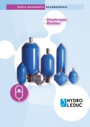
■■The tank:<br />
Generally, hydraulic <strong>pumps</strong> much prefer a tank above the pump.<br />
LEDUC <strong>pumps</strong> can also operate with oil level beneath the pump, for further<br />
information on such installations, please contact our Technical Department.<br />
Correct inlet conditions are between 0.8 to 2 bar absolute pressure.<br />
The tank should preferably have a separation between inlet side and return.<br />
This avoids fluid emulsion and the introduction of air into the hydraulic circuit.<br />
Ensure also that the suction is not from the very bottom of the tank, so as to<br />
protect the pump from any deposits (particles).<br />
■■Hosing:<br />
Should be dimensioned to ensure flow between 0.5 and 0.8 m/second.<br />
Choose as direct a supply line as possible, avoiding sharp bends.<br />
■■Filtration:<br />
Hydro Leduc recommends using a very clean tank, filtered during filling and<br />
with filter on air vent.<br />
The pump supply line must be cleaned (decontaminated) and the return line<br />
should be filtered as follows:<br />
--for relatively simple circuits (e.g. tippers):<br />
use a 20 micron filter on pump return line.<br />
--for more complex circuits (e.g. cranes):<br />
Ideal solution:<br />
--high pressure filter between the pump and the crane hydraulic circuit;<br />
--10 to 20 micron filter;<br />
--clogging indicator.<br />
■■Preparation of the pump:<br />
Before start-up, the <strong>pumps</strong> should preferably be filled with oil.<br />
■■Start-up:<br />
--open the supply valve if there is one;<br />
--check the valve is in “back to tank” position;<br />
--partially unscrew the output fitting;<br />
--start up at low speed, or by successive starts/stops;<br />
--retighten the output connector as soon as air bubbles have disappeared;<br />
--let the pump run for one to two minutes, and check that the flow is well<br />
established;<br />
--check the pump is running correctly, with no vibrations nor abnormal noise;<br />
--after several hours of operation, check the tightening torque of the pump<br />
fixture to PTO.<br />
■■Maintenance:<br />
Some regular checks are necessary, namely:<br />
--tightening of pump to PTO;<br />
--cleanliness of fluid;<br />
--state of filter;<br />
if you notice traces of oil in the plastic tube, it is essential to<br />
check the sealing between PTO and pump.<br />
■■The fluid:<br />
Use a mineral hydraulic oil with viscosity between 10 and 400 cSt. It is in this<br />
viscosity range that the <strong>pumps</strong> keep their volumetric characteristics. If you<br />
wish to use other fluids, please consult our Technical Department.<br />
Maximum temperature of fluid in the pump should not exceed 100°C.<br />
■■Drive and assembly recommendations:<br />
For PTO mount applications, be careful to respect<br />
the tightening recommendations in terms of pump<br />
onto PTO and PTO onto vehicle gearbox.<br />
TXV <strong>pumps</strong> are not designed to withstand any<br />
axial load on the pump shaft. Check your installation<br />
conforms to this requirement.<br />
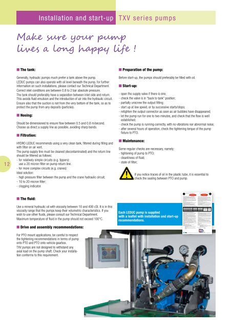
Each LEDUC pump is supplied<br />
with a leaflet with installation and start-up<br />
recommendations.