Variable displacement pumps - Total Hydraulics BV
Variable displacement pumps - Total Hydraulics BV
Variable displacement pumps - Total Hydraulics BV

Create successful ePaper yourself
Turn your PDF publications into a flip-book with our unique Google optimized e-Paper software.
<strong>Variable</strong><br />
<strong>displacement</strong> <strong>pumps</strong><br />
TXVSeries<br />
for<br />
trucks
Contents<br />
■■Why use a variable <strong>displacement</strong> pump?............ 1<br />
■■<strong>Variable</strong> <strong>displacement</strong> .......................... 2<br />
■■Flow-pressure control (LS)....................... 3<br />
■■Range and characteristics ....................... 4<br />
■■Performance. ................................. 5<br />
■■Dimensions ................................ 6-7<br />
■■TXV with through shaft........................ 8-9<br />
■■Controls, settings and fittings.................... 10<br />
TXV <strong>pumps</strong><br />
LEDUC TXV <strong>pumps</strong> are intelligent <strong>pumps</strong>! With variable <strong>displacement</strong> and<br />
pressure-flow control – called Load Sensing – they automatically regulate<br />
to give just what is needed for each movement. Specifically designed for the<br />
needs of the truck hydraulic market, the TXV <strong>pumps</strong> are particularly attractive<br />
solutions for applications in loading cranes, forestry cranes, refuse vehicles,<br />
salt spreaders and snow and ice equipment, and construction equipment<br />
vehicles.<br />
Extremely compact in size (only 125mm wide) to allow direct flange-mounting<br />
on motor PTOs or gearbox PTOs, TXV <strong>pumps</strong> are available in 7 models from<br />
40cc to 150cc maximum <strong>displacement</strong>. Maximum service pressure is up to<br />
440 bar depending on models.<br />
■■Shaft sealing ................................ 11<br />
■■Installation and start-up recommendations.......... 12<br />
■■The complete LEDUC product range.............. 13<br />
A complete range dedicated to truck hydraulics<br />
XP Serie<br />
XP bent axis piston <strong>pumps</strong>,<br />
<strong>displacement</strong> from 12 to 130 cc/rev.<br />
Literature on request or on our website: www.hydroleduc.com<br />
XA SAE<br />
Series<br />
The SAE version of XP bent axis <strong>pumps</strong>.<br />
Literature on request or on our website: www.hydroleduc.com<br />
PA-PAC-PAD<br />
Series<br />
The PA-PAC-PAD pump series comprises three ranges:<br />
single flow 12 to 114 cc/rev, twin-flow of 2x25 to 2x75 cc/rev<br />
and two different flows 75-40 cc/rev.<br />
Literature on request or on our website: www.hydroleduc.com<br />
HYDRO LEDUC<br />
Head Office & Factory<br />
BP 9<br />
F-54122 AZERAILLES (FRANCE)<br />
Tél. +33 (0)3 83 76 77 40<br />
Fax +33 (0)3 83 75 21 58
Why use a variable<br />
<strong>displacement</strong> pump?<br />
<strong>Variable</strong> <strong>displacement</strong>: only advantages!<br />
Installing a TXV variable <strong>displacement</strong> pump will transform your hydraulic<br />
equipment. Slow or rapid movements are done with precision, due to the<br />
constant adjustment of pump flow rate.<br />
1<br />
slow<br />
and precise<br />
2<br />
quick<br />
3 precise control of all<br />
movements<br />
slow<br />
and precise<br />
multi-function capabilities:<br />
● simultaneous movements,<br />
all independant of load<br />
● avoid problems<br />
of fluid over-heating<br />
● reduce energy consumption<br />
1<br />
Q<br />
The pump incorporates a load sensing device to control flow and maximum<br />
pressure.<br />
This is piloted by a proportional valve which sends a signal directly to the<br />
pump to advise of the flow needed by the hydraulic circuits, as a function of<br />
required speed but regardless of load.<br />
1 & 3<br />
For slow, precise movements, the pump can adjust its flow whilst also controlling<br />
pressure. This avoids over-heating of fluid, excessive noise and fluid<br />
degradation which can occur with fixed <strong>displacement</strong> <strong>pumps</strong>.<br />
The motor driving the pump only provides the power actually needed by the<br />
equipment, thus ensuring longer service life of that equipment, significant<br />
gains in energy consumption, and overall a more environmentally<br />
friendly solution.<br />
2<br />
For rapid movements, the pump supplies the required flow virtually<br />
instantaneously.<br />
The proportional movement of<br />
the control lever is perfectly<br />
reproduced.<br />
time
Why use a variable<br />
<strong>displacement</strong> pump?<br />
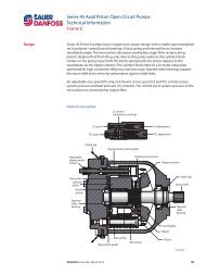
The TXV variable <strong>displacement</strong> <strong>pumps</strong> are of axial piston design, with<br />
11 pistons, thus allowing very slim size envelope (125mm wide), optimal<br />
regularity of flow, and low noise levels.<br />
The <strong>displacement</strong> of the pump is proportional to the stroke of the pistons.<br />
Displacement – and thus flow - is varied by changing the angle of the<br />
swashplate.<br />
To change <strong>displacement</strong> from maximum to zero (complete flow cancellation),<br />
the swashplate angle goes from max. (Fig. 1) to min. (=0) (Fig. 2).<br />
1. Maximum <strong>displacement</strong><br />
2. Zero <strong>displacement</strong><br />
bleed screw<br />
2<br />
<br />
swashplate<br />
bleed screw
Flow-<br />
pressure control (LS)<br />
LS Line<br />
P Line<br />
Spool<br />
Standby<br />
spring<br />
Cancellation piston<br />
Swashplate<br />
Zero flow, standby<br />
The proportional valve is closed. The pressure in the P line increases until<br />
it reaches the value at which the standby spring is set. Under the pressure<br />
in the P line, the spool moves and oil flow supplies the setting piston which<br />
moves the swashplate into vertical position (angle =0): no flow, but standby<br />
pressure is maintained.<br />
Full flow<br />
LS Line<br />
P Line<br />
The proportional valve is fully open, allowing passage of pump flow. The pressure<br />
in the LS line is the same as in the P line. Hydraulic pressure is the same<br />
on either side of the spool. The standby spring holds the spool in its initial<br />
position. The cancellation piston is not supplied with oil. The swashplate is at<br />
maximum angle : the pump is at full <strong>displacement</strong>.<br />
Flow control<br />
3<br />
LS Line<br />
P Line<br />
The proportional valve is partly open. Not all of the pump flow can go through<br />
the valve. Pressure increases in the P line. The pressure in the LS line is the<br />
same as the effort required by the application. Pressures in the P line and in<br />
the LS line + the force of the standby spring balance. Under the pressure in<br />
the P line, the spool moves and an oil flow supplies the cancellation piston<br />
which pushes the swashplate into the position which will give the required<br />
flow.<br />
LS Line<br />
P Line<br />
Zero flow (maximum pressure)<br />
The proportional valve is open, but the cylinder in the application is at a<br />
mechanical stop. Pressure in the system increases to reach the pressure at<br />
which the PC spring is set. This relief valve opens and connects the LS line to<br />
the drain. The pressure drops on the standby spring side. Under the pressure<br />
in the P line, the spool moves and an oil flow supplies the cancellation piston<br />
which pushes the swashplate to vertical position (angle =0): no flow, but<br />
maximum pressure maintained.<br />
PC setting<br />
LS P setting<br />
Drain<br />
LS inlet
TXV series <strong>pumps</strong><br />
main characteristics<br />
Pump<br />
■■standard pump range<br />
TXV 40<br />
TXV 60<br />
TXV 75<br />
TXV 92<br />
TXV 120<br />
TXV 130<br />
TXV 150<br />
0512950<br />
0512955<br />
0512500<br />
0512505<br />
0512510<br />
0512515<br />
0512520<br />
0512525<br />
0515700<br />
0515705<br />
0515300<br />
0515515<br />
0518600<br />
0518605<br />
■■with through shaft<br />
0518700<br />
TXV 130<br />
0518705<br />
Direction<br />
of rotation<br />
SH<br />
SIH<br />
SH<br />
SIH<br />
SH<br />
SIH<br />
SH<br />
SIH<br />
SH<br />
SIH<br />
SH<br />
SIH<br />
SH<br />
SIH<br />
SH<br />
SIH<br />
Displacement (1)<br />
maxi<br />
(cc)<br />
Maximum<br />
operating<br />
pressure<br />
(bar)<br />
Maximum<br />
peak pressure<br />
(intermittent : 5%)<br />
(bar)<br />
Maximum<br />
operating<br />
pressure at<br />
flow-cancellation<br />
(bar)<br />
Max torque<br />
at 300 bar<br />
(Nm)<br />
Max<br />
speed (2)<br />
(rpm)<br />
Weight<br />
(kg)<br />
Overhang<br />
torque<br />
(N.m)<br />
40 400 420 440 220 3000 26.8 35<br />
60 400 420 440 295 2600 26.8 35<br />
75 400 420 440 410 2000 26.8 35<br />
92 380 400 420 483 1900 26.8 35<br />
120 360 380 400 680 2100 26.8 35<br />
130 360 380 400 730 2100 27.2 35<br />
150 310 330 350 840 2000 27.2 35<br />
130 360 380 400 730 1900 31.1 47.4 (3)<br />
(1) TXV <strong>pumps</strong> can be set for smaller maximum <strong>displacement</strong>s: please contact us.<br />
(2) Higher speed possible depending on flow required : please contact us<br />
(3) Overhang torque of the pump only.<br />
Viscosity affects maximum possible rotating speed. If viscosity > 150 cSt, please contact us to obtain corresponding speed possibilities.<br />
4<br />
■■Setting pump maximum <strong>displacement</strong><br />
The TXV <strong>pumps</strong> from 40cc to 120cc are made as standard to be able to use<br />
the setting screw reference 0518386.<br />
The pump <strong>displacement</strong> can thus be adjusted to exactly what is needed.<br />
■■How to use the setting screw<br />
Unscrew 1 completely, loosen 3 and screw 2 to the required <strong>displacement</strong>.<br />
See figure above.<br />
For TXV: 1 turn of the screw changes the <strong>displacement</strong> by 9 cc.<br />
For TXV92 to TXV40: 1 turn of the screw changes the <strong>displacement</strong> by 8 cc.<br />
Back of the pump<br />
1 2 3<br />
X<br />
Displacement of the pump in cc<br />
120<br />
110<br />
100<br />
90<br />
80<br />
70<br />
60<br />
50<br />
40<br />
30<br />
20<br />
10<br />
0<br />
16 18 20 22 24 26 28 30 32 34 36 38<br />
Dimension X - mm<br />
TXV 120<br />
TXV 92
Performances<br />
TXV series <strong>pumps</strong><br />
■■Absorbed torque at maximum <strong>displacement</strong><br />
90<br />
80<br />
70<br />
60<br />
50<br />
40<br />
m.daN<br />
150<br />
130<br />
120<br />
92<br />
75<br />
■■Calculating power as a function of torque<br />
C = (kW)<br />
ω<br />
ω = πN<br />
30<br />
x 100 = m.daN<br />
(kW) = ∆P x Q<br />
600<br />
where:<br />
= theoretical hydraulic power<br />
C = torque<br />
N = speed in rpm<br />
P = working pressure in bar<br />
Q = flow in l/minute<br />
30<br />
20<br />
10<br />
0<br />
0<br />
50<br />
100<br />
200<br />
40<br />
60<br />
300 360<br />
bar<br />
Graph of flow as a function of speed, <strong>displacement</strong> and inlet pressure.<br />
These graphs are the results of tests carried out by the HYDRO<br />
LEDUC Research Laboratory, on a specific test bench, with ISO 46<br />
fluid at 25°C (100 cSt), a 50 mm diameter supply line 1.5 m long,<br />
and a tank with oil level at the same height as the pump.<br />
■■Ideal installation<br />
Tank above the pump<br />
■■Flow<br />
Q (l/min.)<br />
300<br />
150<br />
130<br />
250<br />
130*<br />
120<br />
5<br />
200<br />
92<br />
150<br />
75 60<br />
40<br />
100<br />
50<br />
0<br />
1000<br />
*TXV pump with through shaft.<br />
2000 3000 3600<br />
N (rpm)<br />
■■Volumetric efficiency<br />
Efficiency at 1,500 rpm<br />
%<br />
100<br />
90<br />
0<br />
100<br />
200<br />
300 360<br />
bar
Dimensions<br />
TXV series <strong>pumps</strong><br />
TXV 40 to 120<br />
M 12<br />
Drain G 3/8 "<br />
LS G 1/4 "<br />
PC setting<br />
LS setting<br />
Stand-by<br />
Splines 8-32-36<br />
DIN ISO 14 - NF E 22.131<br />
9<br />
80<br />
194.2<br />
248.1<br />
F<br />
∅ 80 f7<br />
4 x ∅ 12.75<br />
80<br />
125<br />
Connection for<br />
pressure gauge<br />
G 1/4 "<br />
328.2<br />
55.1<br />
6<br />
TXV connections<br />
Pump Outlet pressure Inlet A B<br />
(Ø) (Ø) (mm) (mm)<br />
36<br />
A<br />
6.45<br />
25<br />
25<br />
29<br />
6.45<br />
TXV 40 to 92 G 3/4"<br />
15 19<br />
G 1"1/2<br />
TXV 120 G 1" 6 23.57<br />
View from F<br />
Outlet<br />
View from F<br />
Intlet<br />
B 28 2 x M10 depth 15<br />
28<br />
to attach support device<br />
CW<br />
CCW<br />
■■Support device<br />
In cases where it is necessary to use a support device for the pump, this<br />
MUST be fixed to the same part which the pump is mounted on.<br />
Support<br />
device<br />
■■Mass and position of centre of gravity<br />
CDG<br />
M<br />
screw M10<br />
L (mm) M (kg)<br />
TXV 92 to 40 130 26.8<br />
TXV 120 130 26.8<br />
TXV 130-150 128 27.2<br />
TXV 130 with through shaft 152.6 31.1<br />
L<br />
Dimensions are given only as an indication.
Dimensions<br />
TXV series <strong>pumps</strong><br />
TXV 130 and TXV 150<br />
PC setting<br />
M 12<br />
LS G 1/4 "<br />
Drain G 3/8 "<br />
LS setting<br />
Stand-by<br />
Splines 8-32-36<br />
DIN ISO 14 - NF E 22.131<br />
9<br />
80<br />
219<br />
277<br />
F<br />
∅ 80 f7<br />
4 x ∅ 12.75<br />
55.1<br />
80<br />
127<br />
321.1<br />
7<br />
100<br />
View from F<br />
View from F<br />
Intlet<br />
G 1"½<br />
2 x M10 depth 15<br />
to attach support device<br />
Outlet<br />
G 1"<br />
Connection for<br />
pressure gauge<br />
G 1/4"<br />
29.4<br />
37<br />
CW<br />
CCW<br />
Dimensions are given only as an indication.
Dimensions<br />
TXV series <strong>pumps</strong><br />
TXV130 with through shaft pump<br />
The TXV130 pump exists in a « through shaft » version.<br />
With side porting for inlet and output, this “through shaft” TXV130 configuration<br />
means any LEDUC TXV pump, or fixed <strong>displacement</strong> XP or PA pump, can<br />
be mounted on the back.<br />
As for all the TXV130 <strong>pumps</strong>, the maximum <strong>displacement</strong> of the “through shaft”<br />
TXV130 can be factory set, on request, between 60cc/rev. and 130 cc/rev.<br />
It is important to check that maximum torque to be transmitted by the shaft of<br />
the “through shaft” TXV130 does not exceed 90 m.daN.<br />
2 x M10 depth 15<br />
to attach support device<br />
15<br />
29<br />
Connection for pressure<br />
gauge G 1/4”<br />
PC setting<br />
8<br />
Interface to mount TXV, XP, PA <strong>pumps</strong><br />
(splines 8-32-36 DIN ISO 14 - NF E 22.131)<br />
Drain G 3/8"<br />
Réglage LS<br />
Stand-by<br />
9<br />
Splines 8-32-36<br />
DIN ISO 14 - NF E 22.131<br />
M 12<br />
80<br />
281.5<br />
∅ 80 f7<br />
57.1<br />
55.1<br />
382.6<br />
LS G 1/4"<br />
Outlet G 1”<br />
4 x ∅ 12.75<br />
Intlet G 1”½<br />
Shaft side<br />
80<br />
120<br />
125<br />
80<br />
Rear view<br />
(SH Pump)<br />
Dimensions are given only as an indication.
Dimensions<br />
TXV series <strong>pumps</strong><br />
TXV130 with through shaft pump<br />
On request, the <strong>displacement</strong> of the TXV130 with through shaft pump<br />
can be set for any maximum <strong>displacement</strong> between 60cc and 130cc.<br />
Outlet<br />
Intlet<br />
Intlet<br />
Outlet<br />
SH<br />
SIH<br />
■■Support device<br />
The support device for the pump MUST be fixed to the same part which the<br />
pump is mounted on.<br />
■■Maximum torque transferable by the shaft of the pump driven by the PTO:<br />
C = 90 m.daN.<br />
That is, the sum of torque for both <strong>pumps</strong> must be < 90 m.daN.<br />
9<br />
support device<br />
C<br />
C<br />
Example of 2 TXV <strong>pumps</strong>.<br />
Example of TXV with a XP pump.<br />
C<br />
Example of TXV with a PA pump.<br />
Dimensions are given only as an indication.
Settings<br />
TXV series <strong>pumps</strong><br />
■■Setting maximum <strong>displacement</strong><br />
See page 4.<br />
■■Stand-by<br />
TXV <strong>pumps</strong> are supplied as standard with standby pressure set at 30 bar.<br />
On request, this standby pressure can be set between 25 and 60 bar.<br />
■■Maximum pressure<br />
Cancellation pressure PC of the pump must be the same as the maximum<br />
pressure in the installation: this PC pressure should be stipulated in the order.<br />
If no PC setting is stipulated, <strong>pumps</strong> will be supplied with PC set at 100 bar.<br />
■■Relief valve in the entry plate of proportional valve:<br />
Must be set 25 to 30 bar higher than the chosen PC pressure<br />
■■Response time<br />
Response time of TXV <strong>pumps</strong>, from zero flow up to full flow, can be made<br />
shorter (quicker) on request.<br />
■■TXV pump with constant torque LS control<br />
Description<br />
This constant torque control for the TXV <strong>pumps</strong> ensures that the power<br />
installed in the circuit cannot be exceeded, whilst still allowing control of flow<br />
and of maximum circuit pressure.<br />
The constant torque LS control is available for TXV <strong>pumps</strong> of 40, 60, 75, 92<br />
and 120cc.<br />
This device does not change the external dimensions of the pump.<br />
Principle<br />
The constant torque control means “pressure x flow = constant” is permanently<br />
achieved.<br />
Precision is 5% to 10% around the theoretical curve. The setting is done at<br />
the factory. For each order, please stipulate the pump <strong>displacement</strong>, standby<br />
pressure, and the constant torque level required.<br />
The constant torque control is always complete with constant pressure (PC)<br />
control and flow control.<br />
LS<br />
not supplied<br />
Under development<br />
P<br />
T<br />
A<br />
Inlet fittings<br />
10<br />
Pour utilisation sur l’orifice d’aspiration des pompes TXV.<br />
90° elbow fittings, swivel<br />
F<br />
T<br />
B<br />
E<br />
D<br />
C<br />
A<br />
Reference A ØB C D E F<br />
240131 G 1"½ 40 60 17 61 77<br />
240133 G 1"½ 50 60 17 65 82<br />
Straight fittings<br />
B<br />
■■Example: graph of flow as a function of power<br />
E<br />
D<br />
C<br />
A<br />
Reference A ØB C D E<br />
051523 G 1"½ 40 56 14 54<br />
240067 G 1"½ 50 52 14 66<br />
240066 G 1"½ 60 64 14 69<br />
240186 G 1"½ 63.5 64 14 69<br />
240201 G 1"½ 76.2 80 14 89<br />
Flow (l/min)<br />
200<br />
180<br />
160<br />
140<br />
120<br />
100<br />
P = 75kW<br />
80<br />
P = 55kW<br />
60<br />
P = 47kW<br />
40<br />
P = 35kW<br />
P = 22kW<br />
20<br />
0<br />
0 50 100 150 200 250 300 350 400<br />
pressure (bar)<br />
The constant torque control on the TXV pump shaft is controlled by the Load<br />
Sensing device (flow and pressure regulation).
Shaft sealing<br />
TXV series <strong>pumps</strong><br />
LEDUC <strong>pumps</strong> destined for truck hydraulics are all fitted with reinforced<br />
sealing comprising:<br />
■■Example of tube attachment<br />
●●two radial seals: an external seal adapted to the needs of PTOs and gearboxes;<br />
and an internal seal adapted to the needs of hydraulic performance;<br />
●●an original protection of the pump shaft seals. This is a flexible transparent<br />
tube which avoids any entry of contaminants between the two seals, and<br />
guarantees high pressure water jet cleaning of vehicle will not damage the<br />
sealing area. It also allows air vent of the chamber between the two seals.<br />
11<br />
✔ Recommendations for attaching the protective tube:<br />
●●make a siphon with the tube so as to avoid any introduction of:<br />
- dirt from road;<br />
- water or damp from high pressure washing of vehicle.<br />
●●put the end of the tube downwards, or in a place sheltered from any<br />
projections;<br />
●●fix the tube in place using a collar/clip.<br />
✘ Avoid:<br />
●●attaching the tube to any parts which may move, this could lead to it being<br />
damaged or torn off;<br />
●●any pinching or folds in the tube when fixing it in place;<br />
●●any obturation of the end of the tube.<br />
HHydro Leduc stresses that on non-sealed PTO installations<br />
it is the hydraulic pump which ensures the sealing of the<br />
vehicle gearbox. This is why Hydro Leduc offers tried and<br />
tested solutions approved by vehicle manufacturers.<br />
Note in particular the pump – PTO sealing via a frontal square section<br />
ring seal ensuring metal to metal contact between pump and PTO.
mise en route des pompes txV<br />
stArting up And setting oF txV <strong>pumps</strong><br />
F<br />
ATTENTION<br />
ImpOrTANT :<br />
GB<br />
A lire impérativement<br />
please read before<br />
avant le montage de la<br />
installation !<br />
pompe.<br />
AVAnt de monter lA pompe :<br />
stArting up And setting oF txV <strong>pumps</strong> :<br />
1. Vérifier que les paramètres techniques de la prise de<br />
1. Check that technical parameters of the PTO are compatible<br />
mouvement sont compatibles avec l’utilisation de la pompe<br />
with the use of the TXV pump (necessary drive torque, continuous<br />
TXV (couple utile de transmission, temps d’utilisation, couple de<br />
operating time, overhang torque/ bending moment). See HYDRO<br />
renversement). Se reporter à la notice « Pompe hydraulique à<br />
LEDUC <strong>Variable</strong> Displacement Pumps catalogue.<br />
cylindrée variable ».<br />
2. Check the direction of rotation of the pump according tothe PTO<br />
2. Vérifier le sens de rotation de la pompe par rapport au sens de<br />
(see arrow on pump housing). Looking at the front of the PTO, if<br />
PMT, (voir flèche sur carter de pompe). Si la PMT est sens horaire,<br />
its rotation is clockwise, then the rotation of the pump seen at shaft<br />
le pompe doit tourner sens inverse horaire en regardant l’axe de<br />
end must be anti-clockwise.<br />
pompe face à soi.<br />
MOnTagE DE La POMPE SUR LE VEHiCULE :<br />
aSSEMBLY Of PUMP OnTO VEHiCLE PTO :<br />
- Vérifier la présence du joint carré frontal, bien positionné dans sa Check that there is a front square seal, correctly placed in its<br />
gorge. ne pas utiliser de joint papier ;<br />
groove. Do not use any paper seal.<br />
- En l’absence de préconisations du constructeur de la PMT,<br />
- if no recommendation from PTO manufacturer, grease the splines<br />
graisser les cannelures avec de la graisse MOLiKOTE ;<br />
with MOLiKOTE grease.<br />
- Monter la pompe sur la PMT en assurant le bon couple de<br />
- Mount the pump onto the PTO ensuring tightening torque at all<br />
serrage sur les écrous, suivant les préconisations du constructeur nuts conforms to the PTO manufacturer recommendation.<br />
de la pmt.<br />
RaCCORDEMEnT DES TUYaUTERiES / COnnECTiOn Of HOSES :<br />
Type de pompe / pump type Aspiration / Inlet refoulement / output Ligne LS / LS line Drain<br />
TXV40 à 92 et cylindrées inférieures /<br />
g1” 1/2 g 3/4”<br />
TXV up to and including 92cc <strong>displacement</strong><br />
g 1/4” g 3/8”<br />
txV 120 g1” 1/2 g1”<br />
txV 130 g1” 1/2 g1”<br />
1. Prévoir des raccords cylindriques équipés d’une bague<br />
1. Use cylindrical connectors fitted with a seal to ensure perfect<br />
d’étanchéité afin d’assurer une parfaite étanchéité.<br />
tightness.<br />
2. La durite d’aspiration doit avoir un diamètre intérieur le plus gros 2. The internal diameter of the supply line must be as large as<br />
possible (min 50 mm), et le plus directe possible afin de faciliter<br />
possible (at least 50 mm), and this supply line should be as direct<br />
l’aspiration de l’huile.<br />
as possible to facilitate oil supply to pump.<br />
3. Le tuyau de drain de l’asservissement doit être raccordé<br />
3. The drain line from the LS valve assembly should be connected<br />
directement au réservoir ou éventuellement passer par un<br />
directly to the tank or go through oil cooler if there is one. it must<br />
refroidisseur si l’installation en est équipée. Dans tous les cas, la always be submerged under the oil level in tank. This is to ensure<br />
connexion au réservoir doit se faire en dessous du niveau d’huile. no intake of air is possible when the pump is not used for some<br />
ainsi les prises d’air lors d’un arrêt prolongé sont impossibles.<br />
time.<br />
4. Raccorder directement l’orifice LS de la pompe à l’orifice LS du 4. Connect the LS port of the pump directly to the LS port on the<br />
distributeur proportionnel.<br />
proportional valve.<br />
5. Le tuyau plastique situé à l’avant de la pompe doit être accroché 5. The plastic pipe at the front of the pump should be attached to a<br />
le long d’un flexible hydraulique. attention à ne pas le pincer. il<br />
hydraulic hose. Be careful not to nip it. it protects the sealing and<br />
protège l’étanchéité et permet de visualiser une fuite, dans le cas shows leakage should any occur.<br />
d’une détérioration de l’un des 2 joints d’arbre.<br />
CHOiCE Of fLUiD anD RECOMMEnDED fiLTRaTiOn :<br />
TYPE DE fLUiDE a UTiLiSER ET fiLTRaTiOn PRECOnniSEE : generally use mineral-based hydraulic oil of class iSO 32, iSO<br />
46 or iSO 68 depending on the temperature conditions, to ensure<br />
correct operating viscosity which should be between 10 and 400<br />
cSt.<br />
filtration should be 20T or sufficient to ensure of pollution 18/13 (to<br />
iSO standard 4406)<br />
Bleeding :<br />
En général : huile minérale hydraulique classe iSO 32, iSO 46 et<br />
iSO 68, selon les conditions thermiques pour assurer une viscosité<br />
fonctionnelle correcte, comprise entre 10 et 400 cSt.<br />
Classe de filtration : 20µ ou classe de pollution 18/13 selon norme<br />
iso 4406.<br />
MiSE En HUiLE DE La POMPE :<br />
avant de procéder à la mise en route de la pompe, il est<br />
nécessaire de purger l’air dans la pompe.<br />
■ Si le réservoir est au-dessus de la pompe :<br />
- Desserrer le bouchon de purge le plus haut suivant le<br />
croquis ci-joint ;<br />
- Laisser ouvert jusqu’à écoulement d’un filet d’huile<br />
régulier ;<br />
- Procéder au resserrage du bouchon à la fin de cette<br />
opération.<br />
all air must be bled before starting up the pump.<br />
■ if tank is above the pump :<br />
- Slacken the uppermost bleed plug, see drawing below;<br />
- Wait until there is a regular flow of oil;<br />
- Retighten the screw<br />
assurer la purge par les vis / Perform bleeding<br />
Vis de purge/<br />
Bleed screw<br />
Vis de purge/<br />
Bleed screw<br />
Bp 9 - F 54122 Azerailles - France - tel : (33) 03.83.76.77.40 - Fax : (33) 03.83.75.21.58 - www.hydroleduc.com - mail@hydroleduc.com<br />
Installation and start-up<br />
TXV series <strong>pumps</strong><br />
Make sure your pump<br />
lives a long happy life !<br />
12<br />
■■The tank:<br />
Generally, hydraulic <strong>pumps</strong> much prefer a tank above the pump.<br />
LEDUC <strong>pumps</strong> can also operate with oil level beneath the pump, for further<br />
information on such installations, please contact our Technical Department.<br />
Correct inlet conditions are between 0.8 to 2 bar absolute pressure.<br />
The tank should preferably have a separation between inlet side and return.<br />
This avoids fluid emulsion and the introduction of air into the hydraulic circuit.<br />
Ensure also that the suction is not from the very bottom of the tank, so as to<br />
protect the pump from any deposits (particles).<br />
■■Hosing:<br />
Should be dimensioned to ensure flow between 0.5 and 0.8 m/second.<br />
Choose as direct a supply line as possible, avoiding sharp bends.<br />
■■Filtration:<br />
Hydro Leduc recommends using a very clean tank, filtered during filling and<br />
with filter on air vent.<br />
The pump supply line must be cleaned (decontaminated) and the return line<br />
should be filtered as follows:<br />
--for relatively simple circuits (e.g. tippers):<br />
use a 20 micron filter on pump return line.<br />
--for more complex circuits (e.g. cranes):<br />
Ideal solution:<br />
--high pressure filter between the pump and the crane hydraulic circuit;<br />
--10 to 20 micron filter;<br />
--clogging indicator.<br />
■■Preparation of the pump:<br />
Before start-up, the <strong>pumps</strong> should preferably be filled with oil.<br />
■■Start-up:<br />
--open the supply valve if there is one;<br />
--check the valve is in “back to tank” position;<br />
--partially unscrew the output fitting;<br />
--start up at low speed, or by successive starts/stops;<br />
--retighten the output connector as soon as air bubbles have disappeared;<br />
--let the pump run for one to two minutes, and check that the flow is well<br />
established;<br />
--check the pump is running correctly, with no vibrations nor abnormal noise;<br />
--after several hours of operation, check the tightening torque of the pump<br />
fixture to PTO.<br />
■■Maintenance:<br />
Some regular checks are necessary, namely:<br />
--tightening of pump to PTO;<br />
--cleanliness of fluid;<br />
--state of filter;<br />
if you notice traces of oil in the plastic tube, it is essential to<br />
check the sealing between PTO and pump.<br />
■■The fluid:<br />
Use a mineral hydraulic oil with viscosity between 10 and 400 cSt. It is in this<br />
viscosity range that the <strong>pumps</strong> keep their volumetric characteristics. If you<br />
wish to use other fluids, please consult our Technical Department.<br />
Maximum temperature of fluid in the pump should not exceed 100°C.<br />
■■Drive and assembly recommendations:<br />
For PTO mount applications, be careful to respect<br />
the tightening recommendations in terms of pump<br />
onto PTO and PTO onto vehicle gearbox.<br />
TXV <strong>pumps</strong> are not designed to withstand any<br />
axial load on the pump shaft. Check your installation<br />
conforms to this requirement.<br />
Each LEDUC pump is supplied<br />
with a leaflet with installation and start-up<br />
recommendations.
other product lines<br />
hydraulic motors<br />
XP<br />
Fixed <strong>displacement</strong><br />
bent-axis pistons motors.<br />
Models from 12 to 126 cc.<br />
Available both in ISO<br />
and SAE versions.<br />
TXV<br />
PA<br />
PAC<br />
PAD<br />
piston <strong>pumps</strong><br />
for trucks<br />
HYDRO LEDUC offers 3 types of piston <strong>pumps</strong> perfectly<br />
suited to all truck and PTO-mount applications.<br />
Fixed and variable <strong>displacement</strong> from 12 to 150 cc.<br />
micro-hydraulics<br />
mobile and<br />
industrial <strong>pumps</strong><br />
Fixed <strong>displacement</strong> <strong>pumps</strong>, the W series, and variable<br />
<strong>displacement</strong> <strong>pumps</strong>, the DELTA series. High pressure<br />
capabilities within minimal size.<br />
W series: fl anges to ISO 3019/2, shafts to DIN 5480.<br />
DELTA series: SAE shafts and fl anges.<br />
This is a fi eld of exceptional<br />
HYDRO LEDUC know-how:<br />
• axial and radial piston <strong>pumps</strong>,<br />
of fi xed and variable <strong>displacement</strong>,<br />
• axial piston micro-hydraulic motors,<br />
• micro-hydraulic units incorporating<br />
pump, electric motors, valving, controls,<br />
etc.<br />
To users of hydraulic components which have to<br />
be housed in extremely small spaces,<br />
HYDRO LEDUC offers complete, original and reliable<br />
solutions for even the most diffi cult environments.<br />
we are passionate<br />
about hydraulics…<br />
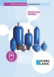
hydro-pneumatic<br />
accumulators<br />
Bladder, diaphragm accumulators.<br />
Spherical and cylindrical accumulators.<br />
Volume capacities from 20 cc to 50 liters.<br />
Pressures up to 500 bar.<br />
Accessories for use with hydraulic accumulators.<br />
A dedicated R&D team means HYDRO LEDUC is able to adapt or create<br />
products to meet specifi c customer requirements. Working in close<br />
cooperation with the decision-making teams of its customers, HYDRO LEDUC optimizes<br />
proposals based on the specifi cations submitted.
a passion<br />
for hydraulics<br />
HYDRO LEDUC<br />
Head Office & Factory<br />
BP 9 - F-54122 AZERAILLES (FRANCE)<br />
Tél. +33 (0)3 83 76 77 40<br />
Fax +33 (0)3 83 75 21 58<br />
HYDRO LEDUC GmbH<br />
Haselwander Str. 5<br />
D-77746 SCHUTTERWALD (DEUTSCHLAND)<br />
Tel. +49 (0) 781-9482590<br />
Fax +49 (0) 781-9482592<br />
HYDRO LEDUC N.A., Inc.<br />
19416 Park Row - Suite 170<br />
HOUSTON, TEXAS 77084 (USA)<br />
Tel. +1 281 679 9654<br />
Fax +1 832 321 3553<br />
Complete catalogues available at:<br />
www.hydroleduc.com<br />
HYDRO LEDUC<br />
SAS with capital of 4 065 000 euros<br />
Siret 319 027 421 00019<br />
RC Nancy B 319 027 421<br />
mail@hydroleduc.com<br />
The information is given as rough guide. Not contractual document. Cancels and replaces previous version.<br />
Editech.com<br />
03/07/2012