SIPS - The Bridge to Secure Electric Power Systems - PAC World ...
SIPS - The Bridge to Secure Electric Power Systems - PAC World ...
SIPS - The Bridge to Secure Electric Power Systems - PAC World ...

You also want an ePaper? Increase the reach of your titles
YUMPU automatically turns print PDFs into web optimized ePapers that Google loves.
48<br />
Wide Area<br />
System Integrity Protection<br />
<strong>The</strong> trend in<br />
power system<br />
planning has<br />
become tight<br />
operating<br />
margins,<br />
with less<br />
redundancy. It<br />
is also apparent<br />
that the<br />
present trend<br />
of load growth<br />
outstripping<br />
transmission<br />
will continue for<br />
the foreseeable<br />
future.<br />
will fall short of the reliability standards our economy<br />
requires, and will result in higher costs <strong>to</strong> consumers.<br />
<strong>The</strong> Transmission program's mission specifically is<br />
<strong>to</strong> develop technologies and policy options that will<br />
contribute <strong>to</strong> maintaining and enhancing the reliability<br />
of the nation's electric power delivery system during the<br />
transition <strong>to</strong> competitive power markets.<br />
<strong>The</strong>re are often many issues <strong>to</strong> address in terms of<br />
reliable system operation, however the primary issue is<br />
typically the heavily loaded transmission system (with<br />
subsequent high reactive power losses/requirements).<br />
This overloading is often at the root of system instability<br />
problems. <strong>The</strong> understanding of the reactive margin<br />
requirements is not lost on legisla<strong>to</strong>rs and regula<strong>to</strong>ry<br />
bodies who have expressed their concerns about potential<br />
blackout scenarios. Reactive power flow analysis, including<br />
mitigation of voltage instability, should become an integral<br />
part of planning and operating studies and have been<br />
mandated in the recent industry recommendations for<br />
prevention and mitigation of future blackout scenarios.<br />
<strong>The</strong> Union for the Coordination of <strong>Electric</strong>ity<br />
Transmission (UCTE) report lists 14 observations for<br />
the September 28, 2003 outage, that are very similar <strong>to</strong><br />
those identified for the outages in North America and in<br />
Europe.<br />
It should be noted that the issues faced, in many cases,<br />
are not easily overcome. Even when new generation is<br />
justified, transmission owners are faced with challenges<br />
such as market forces, permit availability, sighting<br />
opportunities, and strict environmental constraints as<br />
opposed <strong>to</strong> system studies. Under these scenarios, load<br />
centers often end up connected far from generation<br />
resources and through heavily loaded weak transmission<br />
systems. Subsequently, deregulation and the high cost<br />
of building new transmission infrastructures have placed<br />
the transmission owners under increasing pressure <strong>to</strong><br />
maximize asset utilization. Transmission opera<strong>to</strong>rs note<br />
that they have credible contingency situations that can<br />
result in voltage collapse or system instability challenges<br />
imposed by insufficient levels of reactive compensation.<br />
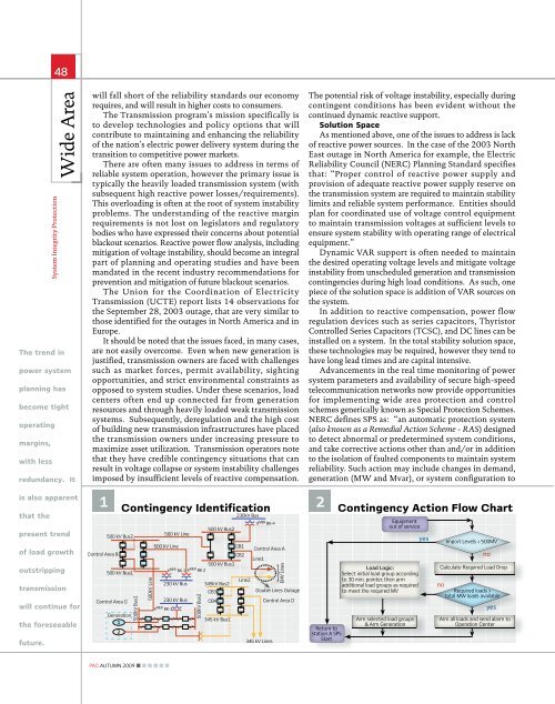
1 Contingency Identification<br />
Control Area B<br />
500 kV Bus2<br />
500 kV Bus1<br />
Control Area C<br />
Generation<br />
1<br />
2<br />
500kV Bus1<br />
500kV Line<br />
500 kV Line<br />
500 kV Line<br />
230 kV Bus<br />
230 kV Bus<br />
500kV Bus2<br />
500 kV Bus2<br />
500 kV Bus1<br />
345kV Bus2<br />
CB3<br />
CB4<br />
345 kV Bus1<br />
230kV Bus<br />
CB1<br />
CB2<br />
Line2<br />
Control Area A<br />
Line1<br />
Double Lines Outage<br />
345 kV Lines<br />
EHV Lines<br />
Control Area D<br />
<strong>The</strong> potential risk of voltage instability, especially during<br />
contingent conditions has been evident without the<br />
continued dynamic reactive support.<br />
Solution Space<br />
As mentioned above, one of the issues <strong>to</strong> address is lack<br />
of reactive power sources. In the case of the 2003 North<br />
East outage in North America for example, the <strong>Electric</strong><br />
Reliability Council (NERC) Planning Standard specifies<br />
that: “Proper control of reactive power supply and<br />
provision of adequate reactive power supply reserve on<br />
the transmission system are required <strong>to</strong> maintain stability<br />
limits and reliable system performance. Entities should<br />
plan for coordinated use of voltage control equipment<br />
<strong>to</strong> maintain transmission voltages at sufficient levels <strong>to</strong><br />
ensure system stability with operating range of electrical<br />
equipment.”<br />
Dynamic VAR support is often needed <strong>to</strong> maintain<br />
the desired operating voltage levels and mitigate voltage<br />
instability from unscheduled generation and transmission<br />
contingencies during high load conditions. As such, one<br />
piece of the solution space is addition of VAR sources on<br />
the system.<br />
In addition <strong>to</strong> reactive compensation, power flow<br />
regulation devices such as series capaci<strong>to</strong>rs, Thyris<strong>to</strong>r<br />
Controlled Series Capaci<strong>to</strong>rs (TCSC), and DC lines can be<br />
installed on a system. In the <strong>to</strong>tal stability solution space,<br />
these technologies may be required, however they tend <strong>to</strong><br />
have long lead times and are capital intensive.<br />
Advancements in the real time moni<strong>to</strong>ring of power<br />
system parameters and availability of secure high-speed<br />
telecommunication networks now provide opportunities<br />
for implementing wide area protection and control<br />
schemes generically known as Special Protection Schemes.<br />
NERC defines SPS as: “an au<strong>to</strong>matic protection system<br />
(also known as a Remedial Action Scheme - RAS) designed<br />
<strong>to</strong> detect abnormal or predetermined system conditions,<br />
and take corrective actions other than and/or in addition<br />
<strong>to</strong> the isolation of faulted components <strong>to</strong> maintain system<br />
reliability. Such action may include changes in demand,<br />
generation (MW and Mvar), or system configuration <strong>to</strong><br />
1 12<br />
Contingency Action Flow Chart<br />
Return <strong>to</strong><br />
station A SPS<br />
Start<br />
Equipment<br />
out of service<br />
Load Logic:<br />
Select initial load group according<br />
<strong>to</strong> 30 min. pointer, then arm<br />
additional load groups as required<br />
<strong>to</strong> meet the required MV<br />
Arm selected load groups<br />
& Arm Generation<br />
yes<br />
Import Levels < 500MV<br />
no<br />
Calculate Required Load Drop<br />
no<br />
Required loads ><br />
<strong>to</strong>tal MW loads available<br />
yes<br />
Arm all loads and send alarm <strong>to</strong><br />
Operation Center<br />
<strong>PAC</strong>.AUTUMN.2009