SIPS - The Bridge to Secure Electric Power Systems - PAC World ...
SIPS - The Bridge to Secure Electric Power Systems - PAC World ...
SIPS - The Bridge to Secure Electric Power Systems - PAC World ...

Create successful ePaper yourself
Turn your PDF publications into a flip-book with our unique Google optimized e-Paper software.
y Vahid Madani, Jon Sykes, PG&E, and Mark Adamiak, GE Multilin, USA<br />
maintain system stability, acceptable voltage, or power<br />
flows.<br />
SPS Design Process<br />
In this article, the SPS design process is broken<br />
down in<strong>to</strong> five steps, namely: 1 System Study; 2<br />
Solution Development; 3 Design and Implementation;<br />
4 Commissioning / Periodic Testing; 5 Training &<br />
Documentation. Items <strong>to</strong> be considered in each of these<br />
steps are described in the sections below.<br />
1. System Study<br />
In order <strong>to</strong> design a wide area moni<strong>to</strong>ring and<br />
prevention scheme, accurate system studies need <strong>to</strong><br />
be completed <strong>to</strong> identify the ensemble of contingency<br />
scenarios and <strong>to</strong> define the parameters required for proper<br />
implementation. Some of the critical items include:<br />
Understanding the requirements and the intent of<br />
the application – (different requirements result in different<br />
solutions)<br />
Types of studies <strong>to</strong> be performed – Planning and<br />
Operating studies, followed by on-going system studies<br />
including protection coordination studies<br />
Evaluating multiple solutions – Studying alternatives<br />
and performing contingency analysis<br />
On-going dialog with all entities involved – Internal<br />
and external (Regional)<br />
Identifying moni<strong>to</strong>ring quantities, locations and set<br />
points – overload conditions, undervoltage,<br />
underfrequency, phasor measurement<br />
Arming conditions and levels – Determining whether<br />
the scheme arming should be power system condition<br />
based or outage/contingency based<br />
Contingency identification<br />
Identify islanding points if applicable<br />
Voltage or phase angle stability<br />
System res<strong>to</strong>ration process; Cold Load Pickup<br />
considerations<br />
Wide area moni<strong>to</strong>ring and intelligent dispatch<br />
Reliability and dependability levels – Redundancy,<br />
Voting, Fail safe, etc.<br />
System studies identify limitations or restrictions. <strong>The</strong><br />
limitations may be thermal, voltage, or angular instability<br />
related limits wherein the latter items are of significantly<br />
more concern than thermal capacity limits. It should<br />
be noted, however, that relaxing non-thermal limits<br />
in a cost-effective fashion can be very challenging in a<br />
deregulated environment.<br />
2. Solution Development<br />
Once the system studies are completed, the solution<br />
space must be analyzed and specific recommendations<br />
must be made. Figure 1 shows an example area that might<br />
have been modeled in a system study. <strong>The</strong> figure depicts<br />
outages (breakers open are filled inside) and/or overloads<br />
on particular pieces of equipment. Of note in this example<br />
is the fact that a genera<strong>to</strong>r outage in one area of the system<br />
coupled with the outage of one line near Control Area B<br />
and C of the system and an overload on two other lines<br />
Moni<strong>to</strong>ring 3 EHV Substations<br />
<strong>The</strong> fundamental changes in<br />
the design and operation of the<br />
electric power system require<br />
that system-wide protection<br />
solutions be implemented.<br />
near Control Area A and B of the system will create a<br />
potential voltage collapse or generation/load imbalance<br />
scenario.<br />
Given the defined contingencies, a method of<br />
conveying the actions for a given contingency is required.<br />
One technique is <strong>to</strong> migrate the moni<strong>to</strong>red quantities<br />
and subsequent state transitions in a flowchart. Figure 2<br />
illustrates such a flow-chart for a situation where remedial<br />
action is required for a particular piece of equipment<br />
being out of service. Once the outage is detected, updated<br />
power flow measurements are used <strong>to</strong> determine whether<br />
any arming is needed. If the measured line flows are less<br />
than the value from the study (500 MW in this example),<br />
stable system operation can be expected. However, when<br />
line flows exceed the limits identified by system studies,<br />
the system is au<strong>to</strong>matically armed for a pre-calculated<br />
load-shed upon detection of the next defined contingency.<br />
In this example, the amount of load shed needed is<br />
compared against that available and then an optimal<br />
load-shed decision is selected.<br />
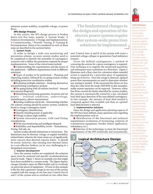
3. Implementation Solutions<br />
Once the design and application planning aspects of<br />
the SPS have been defined, many questions arise regarding<br />
the implementation such as:<br />
Identification of the functional and technical<br />
requirements (evaluation of moni<strong>to</strong>ring, isolation of<br />
transmission equipment, breaker failure application,<br />
redundancy, etc.)<br />
Selection of the technology <strong>to</strong> meet the functional<br />
requirements of the SPS technically and economically,<br />
3<br />
1 Logical Architecture Design<br />
500 kV Lines 230 kV<br />
sub<br />
station 1<br />
Load Group of<br />
sub<br />
stations<br />
345 kV Lines<br />
sub<br />
station 2<br />
230 kV Lines<br />
sub<br />
station 3<br />
Line Out of Service<br />
Network<br />
How much load <strong>to</strong> drop and in<br />
which part of the system?<br />
Load<br />
Load<br />
115 kV<br />
Group of<br />
sub<br />
stations<br />
12 kV<br />
Group of<br />
sub<br />
stations<br />
49<br />
Vahid Madani -<br />
IEEE Fellow, is the<br />
primary architect<br />
and developer<br />
of standards in<br />
protection & control<br />
integration applications<br />
and substation<br />
modernization at<br />
Pacific Gas and <strong>Electric</strong><br />
Co. (PG&E).<br />
He is a Tau Beta<br />
Pi member, and a<br />
registered <strong>Electric</strong>al<br />
Engineer with more<br />
than 25 years of<br />
academic and utility<br />
experience, and<br />
recipient of many<br />
honorary and distinguished<br />
citations.<br />
For a decade, he<br />
served as Chair<br />
of the WECC RAS<br />
Reliability Subcommittee<br />
and received<br />
the best Chair<br />
Person award for his<br />
leadership twice. He<br />
Chairs the Performance<br />
Standards<br />
Task Team within<br />
the North American<br />
Synchrophasor<br />
Initiative (NASPI).<br />
Mr. Madani is the<br />
author of more than<br />
60 publications,<br />
the co-edi<strong>to</strong>r of<br />
the 2006 McGraw<br />
Hill year book of<br />
science technology,<br />
and the 2008 Edition<br />
of International<br />
Journal of Reliability<br />
and Safety (IJRS)<br />
for InderScience<br />
Publishing.<br />
<strong>PAC</strong>.AUTUMN.2009