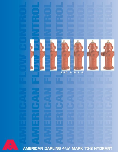
American Darling 4 1/2" Mark 73-2 Hydrant -- 250 P.S.I.G. - scardo.at
American Darling 4 1/2" Mark 73-2 Hydrant -- 250 P.S.I.G. - scardo.at
American Darling 4 1/2" Mark 73-2 Hydrant -- 250 P.S.I.G. - scardo.at
Create successful ePaper yourself
Turn your PDF publications into a flip-book with our unique Google optimized e-Paper software.
AMERICAN FLOW CONTROL<br />
AMERICAN FLOW CONTROL<br />
AMERICAN FLOW CONTROL<br />
AMERICAN FLOW CONTROL<br />
AMERICAN FLOW CONTROL<br />
AMERICAN FLOW CONTROL<br />
AMERICAN FLOW CONTROL<br />
AMERICAN FLOW CONTROL<br />
AMERICAN FLOW CONTROL<br />
2 5 0 P . S . I . G .<br />
AMERICAN DARLING 4 1 /2" MARK <strong>73</strong>-2 HYDRANT
CONSTRUCTION<br />
AMERICAN FLOW CONTROL<br />
4 1/2" MARK <strong>73</strong>-2<br />
OPERATING NUT-cast one piece<br />
bronze oper<strong>at</strong>ing nut. Design of the<br />
oper<strong>at</strong>ing thread permits slow closing<br />
of the hydrant valve, reducing the<br />
possibility of w<strong>at</strong>er hammer.<br />
PIPE PLUG-provides access to<br />
lubric<strong>at</strong>ion chamber. Pipe plug can<br />
be replaced with lubric<strong>at</strong>ing fitting to<br />
lubric<strong>at</strong>e the rod threads and thrust<br />
washers.<br />
O-RINGS-seal lubric<strong>at</strong>ion chamber,<br />
assure dry-top hydrant, reduce<br />
friction, prevent w<strong>at</strong>er from reaching<br />
the oper<strong>at</strong>ing mechanism.<br />
TOP TRAVEL STOP NUT-provides a<br />
positive limit to main rod travel.<br />
Elimin<strong>at</strong>es contact of valve bottom<br />
with interior of base, thereby protecting<br />
co<strong>at</strong>ing.<br />
HYDRANT ROD-furnished in two<br />
sections of high-tensile steel. Upper<br />
section has bronze sleeve where it<br />
passes through O-Rings. Upper and<br />
lower sections are connected by cast<br />
iron coupling using stainless steel pins.<br />
DRAIN LEVER-rugged bronze lever performs<br />
dual function as carrier for drain<br />
lever washers and as wrench to<br />
remove working parts.<br />
HYDRANT SEAT-made of bronze, with<br />
accur<strong>at</strong>ely machined se<strong>at</strong> for hydrant<br />
valve with (2) drain ports.<br />
HYDRANT SPRING-assures quick drain<br />
closure and allows throttling.<br />
BOLTS AND NUTS-all bolts and nuts are<br />
pl<strong>at</strong>ed steel for corrosion resistance.<br />
HYDRANT VALVE-consists of a gray iron<br />
valve top and valve bottom and<br />
hydrant valve rubber. Rod threads are<br />
permanently sealed from contact with<br />
w<strong>at</strong>er. <strong>Hydrant</strong> valve seals against the<br />
bronze hydrant se<strong>at</strong>.<br />
WEATHER COVER (gray iron with rubber<br />
we<strong>at</strong>her shield)-The word "open" and an<br />
arrow show direction to turn the oper<strong>at</strong>ing<br />
nut. The rubber we<strong>at</strong>her shield prevents<br />
w<strong>at</strong>er and debris from entering<br />
the housing area.<br />
HOUSING AND HOUSING COVERretain<br />
oper<strong>at</strong>ing nut and thrust washer.<br />
Rugged construction withstands oper<strong>at</strong>ing<br />
forces.<br />
THRUST WASHER-takes upward thrust<br />
when opening hydrant valve and<br />
reduces oper<strong>at</strong>ing torque.<br />
NOZZLES-p<strong>at</strong>ented Amlok design<br />
allows field replacement of damaged<br />
nozzles in minutes by one person.<br />
UPPER BARREL-gray iron with markings<br />
identifying size, model and year of<br />
manufacture.<br />
TRAFFIC FEATURE-Upper barrel is connected<br />
to lower barrel with breakable<br />
traffic flange and 8 bolts and nuts. This<br />
fe<strong>at</strong>ure allows 360° rot<strong>at</strong>ion of upper<br />
nozzle section.<br />
LOWER BARREL-The ductile iron lower<br />
barrel provides extra strength against<br />
traffic impact damage.<br />
HYDRANT DRAIN RING-securely held<br />
between barrel and base flange, provides<br />
bronze-to-bronze threaded connection<br />
for hydrant se<strong>at</strong>. Serves as noncorrosive<br />
multiport (4) drain channel.<br />
BASE-spherical-shaped base has no<br />
projections or cavities to obstruct flow<br />
or collect sediment. 6" M.J. base is<br />
ductile iron.<br />
Fully complies with AWWA C502 and is available UL 246 and Factory Mutual Approved for allowable configur<strong>at</strong>ions.<br />
1
SECTIONAL DRAWINGS/DIMENSIONS<br />
AMERICAN FLOW CONTROL<br />
4 1/2" MARK <strong>73</strong>-2<br />
2
PARTS LIST<br />
AMERICAN FLOW CONTROL<br />
4 1/2" MARK <strong>73</strong>-2<br />
PART NO. QTY. DESCRIPTION MATERIAL<br />
<strong>73</strong>-1 1 Oper<strong>at</strong>ing Nut Bronze<br />
<strong>73</strong>-2-1 1 Cover O-Ring Buna N<br />
<strong>73</strong>-2-2 2 Housing O-Rings Buna N<br />
<strong>73</strong>-4-4 1 Thrust Washer Nyl<strong>at</strong>ron<br />
<strong>73</strong>-5-3 1 Pipe Plug Steel<br />
<strong>73</strong>-7-7 1 We<strong>at</strong>her Cover Gray Iron<br />
<strong>73</strong>-9 1 Housing Cover Gray Iron<br />
<strong>73</strong>-11-2 4 Cover Cap Screws see note 4<br />
<strong>73</strong>-13 1 Cover Gasket Fiber<br />
<strong>73</strong>-14 1 Housing Gasket Composition Rubber<br />
<strong>73</strong>-15 1 Housing Gray Iron<br />
<strong>73</strong>-16 6 Housing Bolts and Nuts see note 4<br />
<strong>73</strong>-18-9 1 Upper Barrel Gray Iron<br />
<strong>73</strong>-19-SR 1 Lower Barrel Ductile Iron<br />
<strong>73</strong>-20-3 2 Hose Nozzles Bronze (see note 8)<br />
<strong>73</strong>-20-4 2 Hose Nozzle O-Rings Buna N<br />
<strong>73</strong>-20-5 2 Hose Nozzle Spacer O-Rings Buna N<br />
<strong>73</strong>-21 2 Hose Caps Gray Iron<br />
<strong>73</strong>-22 2 Hose Cap Gaskets Rubber<br />
<strong>73</strong>-23-1 1 Per Nozzle Cap Chains Steel<br />
<strong>73</strong>-23-2 1 Per Nozzle S Hook Steel<br />
<strong>73</strong>-24-3 1 Per Nozzle Nozzle Set Screw Stainless Steel<br />
<strong>73</strong>-24-4 2 Hose Nozzle Internal Stainless Steel<br />
Set Screws<br />
<strong>73</strong>-24-5 1 Per Nozzle Pumper Nozzle Internal Stainless Steel<br />
Set Screw<br />
<strong>73</strong>-25-3 1 or 0 Pumper Nozzle Bronze (see note 8)<br />
<strong>73</strong>-25-4 1 Per Nozzle Pumper Nozzle O-Ring Buna N<br />
<strong>73</strong>-25-5 1 Per Nozzle Pumper Nozzle, Spacer Buna N<br />
O-Ring<br />
<strong>73</strong>-26 1 Per Nozzle Steamer Cap Gray Iron<br />
<strong>73</strong>-27 1 Per Nozzle Steamer Cap Gasket Rubber<br />
<strong>73</strong>-29-13 2 Barrel Flanges Ductile Iron<br />
<strong>73</strong>-29-14 2 Snap Rings Stainless Steel<br />
<strong>73</strong>-29-30 1 Rod Coupling Gray Iron<br />
<strong>73</strong>-29-31 2 Coupling & Cotter Pins Stainless/Bronze<br />
<strong>73</strong>-29-45 1 Breakable Flange Gray Iron<br />
<strong>73</strong>-30-03 1 <strong>Hydrant</strong> Spring Spring Steel<br />
<strong>73</strong>-30-04 1 Spring Pl<strong>at</strong>e Steel<br />
<strong>73</strong>-30-06 1 Travel Stop Nut Bronze<br />
<strong>73</strong>-30-07 1 Spring Pl<strong>at</strong>e Pin Steel<br />
<strong>73</strong>-30-11 1 Upper Rod Steel<br />
<strong>73</strong>-30-12 1 Lower Rod Steel<br />
<strong>73</strong>-31 1 Drain Lever Bronze (see note 8)<br />
<strong>73</strong>-33 2 Drain Lever Washers Rubber<br />
<strong>73</strong>-34 2 Drain Lever Rivets Bronze<br />
<strong>73</strong>-35-02 1 <strong>Hydrant</strong> Se<strong>at</strong> Bronze (see note 8)<br />
<strong>73</strong>-36-1 2 Se<strong>at</strong> O-Rings Buna N<br />
<strong>73</strong>-37 1 Drain Ring Bronze (see note 8)<br />
<strong>73</strong>-38 2 Drain Ring Gaskets Composition Rubber<br />
<strong>73</strong>-38-1 1 Barrel Gasket Composition Rubber<br />
<strong>73</strong>-39 8 Base Bolts and Nuts see note 4<br />
<strong>73</strong>-39-9 8 Barrel Bolts and Nuts see note 4<br />
<strong>73</strong>-40 1 Valve Top Gray Iron<br />
<strong>73</strong>-40-4 1 Valve Top Cotter Pin Stainless Steel<br />
<strong>73</strong>-41 1 <strong>Hydrant</strong> Valve Rubber<br />
<strong>73</strong>-42 1 Valve Bottom Gray Iron<br />
<strong>73</strong>-46-2 1 Flanged Base Gray Iron<br />
<strong>73</strong>-46-5 1 Mechanical Joint Base Ductile Iron<br />
<strong>73</strong>-46-TY 1 Tyton Base Gray Iron<br />
<strong>73</strong>-144 1 We<strong>at</strong>her Shield Rubber<br />
<strong>73</strong>-145 1 Rod Sleeve Bronze<br />
<strong>73</strong>-146 2 Sleeve O-Rings Buna N<br />
NOTES<br />
1. Size and shape of nut on oper<strong>at</strong>ing<br />
nut and cap, threading on nozzles<br />
and caps, and the direction of<br />
opening made to specific<strong>at</strong>ions.<br />
2. Cap chains are not furnished unless<br />
specified.<br />
3. All gray iron is ASTM A126 class B.<br />
4. Bolts and nuts are rust-proofed steel<br />
ASTM A307 in accordance with<br />
AWWA C502.<br />
5. Working pressure <strong>250</strong> p.s.i.g., test<br />
pressure 500 p.s.i.g.<br />
6. <strong>Hydrant</strong> conforms to AWWA specific<strong>at</strong>ions<br />
C502.<br />
7. Upper Barrel can be rot<strong>at</strong>ed 360°.<br />
8. Bronze in contact with w<strong>at</strong>er contains<br />
less than 16% zinc.<br />
9. All Bases except 4” MJ with lugs are<br />
ductile iron.<br />
10. Se<strong>at</strong> and shell test 500 p.s.i.g.<br />
11. Nominal turns to open is 19 1 /2.<br />
Depth of trench or bury<br />
Size and type of base<br />
connection<br />
Direction to open<br />
Paint color<br />
Number of hose nozzles<br />
Hose nozzle size<br />
Steamer nozzle<br />
Steamer nozzle size<br />
Nozzle cap chains<br />
City specified<br />
SUBMITTAL DATA<br />
4"<br />
M.J.<br />
FLG<br />
LEFT<br />
(CCW)<br />
YES<br />
YES<br />
6"<br />
M.J. Tyton<br />
FLG<br />
2<br />
RIGHT<br />
(CW)<br />
NO<br />
NO<br />
8"<br />
M.J.<br />
3
FEATURES/BENEFITS<br />
SPECIFICATIONS<br />
AMERICAN FLOW CONTROL<br />
4 1/2" MARK <strong>73</strong>-2<br />
FEATURES<br />
<strong>American</strong> Flow Control's <strong>American</strong>-<br />
<strong>Darling</strong> <strong>Mark</strong> <strong>73</strong>-2 hydrant incorpor<strong>at</strong>es<br />
over 80 years of experience in<br />
design, manufacture and field experience.<br />
This means dependable and<br />
efficient oper<strong>at</strong>ion when needed.<br />
Introduced in 1977, the <strong>Mark</strong> <strong>73</strong>-2<br />
hydrant is r<strong>at</strong>ed <strong>at</strong> <strong>250</strong> p.s.i.g. and is<br />
se<strong>at</strong> tested <strong>at</strong> 500 p.s.i.g. This hydrant<br />
meets or exceeds all requirements of<br />
AWWA C502 for dry barrel hydrants.<br />
The <strong>Mark</strong> <strong>73</strong>-2 hydrant is loaded<br />
with the fe<strong>at</strong>ures you expect from a<br />
high quality fire hydrant. The all bronze<br />
se<strong>at</strong> and drain ring assure th<strong>at</strong> the<br />
<strong>Mark</strong> <strong>73</strong>-2 hydrant is easily repaired by<br />
just one person.<br />
Optional UL-FM<br />
The <strong>Mark</strong> <strong>73</strong>-2 hydrant is listed by<br />
Underwriters Labor<strong>at</strong>ories, Inc., as<br />
meeting their standard UL 246, l<strong>at</strong>est<br />
edition. The Factory Mutual Research<br />
Corpor<strong>at</strong>ion has approved the<br />
<strong>Mark</strong> <strong>73</strong>-2. Both Underwriters<br />
Labor<strong>at</strong>ories and Factory Mutual<br />
Research Corpor<strong>at</strong>ion require th<strong>at</strong> we<br />
consistently manufacture and test our<br />
hydrants in full compliance with their<br />
stringent requirements. Our facilities are<br />
subject to periodic inspections to<br />
assure we are in compliance with their<br />
standards.<br />
The <strong>Mark</strong> <strong>73</strong>-2 hydrant has these standard fe<strong>at</strong>ures:<br />
. Positive compression, fast<br />
closing drains<br />
. Travel stop loc<strong>at</strong>ed in top<br />
of hydrant<br />
. Bronze-to-bronze se<strong>at</strong>ing<br />
. Short, lightweight,<br />
disassembly wrench<br />
. Easy 360 o rot<strong>at</strong>ion of nozzle<br />
section<br />
. All 6” bases are ductile iron<br />
. Centrifugally cast highstrength<br />
ductile iron lower<br />
barrel<br />
. Sealed lubric<strong>at</strong>ion chamber<br />
BENEFITS<br />
Spring Loaded Multi-port Drains<br />
There are two drain ports and four<br />
drain outlets as a standard fe<strong>at</strong>ure on<br />
the <strong>Mark</strong> <strong>73</strong>-2 hydrant. The rod spring<br />
assures drains close after approxim<strong>at</strong>ely<br />
three turns of the oper<strong>at</strong>ing<br />
nut. This important safety fe<strong>at</strong>ure<br />
prevents wash-outs th<strong>at</strong> can happen<br />
on hydrant designs th<strong>at</strong> do not have<br />
this important fe<strong>at</strong>ure.<br />
Sealed Lubric<strong>at</strong>ion Chamber<br />
Seals oper<strong>at</strong>ing threads from w<strong>at</strong>er<br />
and debris which gre<strong>at</strong>ly reduces<br />
routine maintenance.<br />
Top Travel Stop Nut<br />
Helps prevent stem buckling and<br />
damage to bronze components which<br />
may occur if excessive torque is<br />
applied in the full open position.<br />
SPECIFICATIONS<br />
Fire hydrants shall meet or exceed<br />
AWWA C502, l<strong>at</strong>est revision. R<strong>at</strong>ed<br />
working pressure shall be <strong>250</strong> p.s.i.g.,<br />
test pressure shall be 500 p.s.i.g., and<br />
hydrants shall include the following<br />
specific design criteria:<br />
The main valve closure shall be of<br />
the compression type. Traffic fe<strong>at</strong>ure to<br />
be designed for easy 360º rot<strong>at</strong>ion of<br />
nozzle section during field install<strong>at</strong>ion.<br />
The main valve opening shall not be<br />
less than 4 1/2" and be designed so<br />
th<strong>at</strong> removal of all working parts can<br />
be accomplished without excav<strong>at</strong>ing.<br />
The bronze se<strong>at</strong> shall be threaded into<br />
m<strong>at</strong>ing threads of bronze. The draining<br />
system of the hydrant shall be bronze<br />
and positively activ<strong>at</strong>ed by the main<br />
oper<strong>at</strong>ing rod. <strong>Hydrant</strong> drains shall<br />
close completely after no more than<br />
three turns of the oper<strong>at</strong>ing nut. There<br />
shall be a minimum of (2) internal ports<br />
and (4) drain port outlets to the exterior<br />
of the hydrant. Drain shutoff to be by<br />
direct compression closure.<br />
Lower hydrant barrel shall be made<br />
of centrifugally cast ductile iron.<br />
Friction loss not to exceed 3.0 p.s.i.g.<br />
<strong>at</strong> 1000 gpm through 4 1/2" pumper<br />
nozzle. <strong>Hydrant</strong>s shall be equal to<br />
<strong>American</strong> Flow Control's <strong>American</strong>-<br />
<strong>Darling</strong> <strong>Mark</strong> <strong>73</strong>-2.<br />
4
®<br />
<strong>American</strong> Flow Control<br />
<strong>American</strong>-<strong>Darling</strong> Valve and W<strong>at</strong>erous<br />
A Division of <strong>American</strong> Cast Iron Pipe Company<br />
http://www.acipco.com/afc<br />
<strong>American</strong>-<strong>Darling</strong> Valve<br />
P.O. Box 2727<br />
Birmingham, AL 35202-2727<br />
Phone: 1-800-326-7861<br />
Fax: 1-800-610-3569<br />
e-mail: bp<strong>at</strong>ton@acipco.com<br />
W<strong>at</strong>erous Company<br />
125 Hardman Avenue South<br />
South St. Paul, MN 55075-1191<br />
Phone: 1-888-266-3686<br />
Fax: 1-800-601-2809<br />
e-mail: medybedahl@w<strong>at</strong>erousco.com<br />
Distributed By:


