MAPAL Competence â Actuating Tools and Facing Heads
MAPAL Competence â Actuating Tools and Facing Heads
MAPAL Competence â Actuating Tools and Facing Heads

Create successful ePaper yourself
Turn your PDF publications into a flip-book with our unique Google optimized e-Paper software.
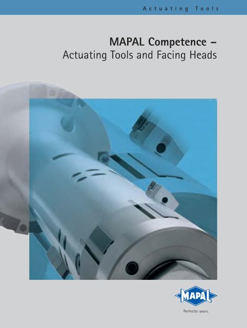
<strong>Actuating</strong> <strong>Tools</strong><br />
<strong>MAPAL</strong> <strong>Competence</strong> –<br />
<strong>Actuating</strong> <strong>Tools</strong> <strong>and</strong> <strong>Facing</strong> <strong>Heads</strong>
The <strong>MAPAL</strong> ISOTOOL <strong>Competence</strong> Center<br />
in Sinsheim<br />
The <strong>MAPAL</strong> group develops, produces <strong>and</strong> markets high quality<br />
precision tools worldwide for the metal cutting industry.<br />
Advice <strong>and</strong> on site technical service are fundamentally important<br />
issues for customer satisfaction on any market.<br />
In order to meet the dem<strong>and</strong> for complete tooling programs,<br />
<strong>MAPAL</strong> has also included complex actuating tools <strong>and</strong> facing<br />
heads in its broad range of products since the 1990s.<br />
<strong>Actuating</strong> tools from the <strong>MAPAL</strong> ISOTOOL GmbH in Sinsheim<br />
offer maximum potential for rationalization <strong>and</strong> optimization<br />
in large batch production. Whether on special machines or<br />
flexible machining centers, wherever complex contours, different<br />
diameters, faces or grooves need to be machined with just<br />
one tool, <strong>MAPAL</strong> will provide the right tooling solution.<br />
The experienced <strong>and</strong> highly specialised <strong>MAPAL</strong> engineering<br />
team will work out the best possible solution with the<br />
customer.<br />
The elaborate, precisely inter-coordinated mechanics <strong>and</strong> the<br />
large number of different components within an actuating<br />
tool require maximum precision <strong>and</strong> care at each step of production.<br />
<strong>MAPAL</strong> ISOTOOL achieves this high precision by an<br />
exclusively manual production process.<br />
3
The Combination is the thing ...<br />
+ =<br />
The <strong>MAPAL</strong> actuating tools with guide pads represent all our experiences in metal-cutting.<br />
New types of high performance tools emerged from proven technologies.<br />
Development, design, production <strong>and</strong> service to the<br />
highest precision provide the basis for products<br />
from <strong>MAPAL</strong>..<br />
In general, <strong>MAPAL</strong> provides a guarantee for the function of the actuating tools<br />
developed <strong>and</strong> produced. For critical trial tools, however, development is always<br />
coordinated <strong>and</strong> concluded with the customer.<br />
In order to complete the installation of the tools at the customer’s works as quickly<br />
<strong>and</strong> efficiently as possible, an extensive trials program is conducted for all actuating<br />
tools under extreme stress <strong>and</strong> real application conditions.<br />
Installation is then carried out at the customer’s works by a <strong>MAPAL</strong> cutting tool<br />
specialist.<br />
Over the next few pages <strong>MAPAL</strong> will introduce a selection of typical complex<br />
actuating tools together with the proven series of st<strong>and</strong>ard facing heads which are<br />
already in use worldwide.<br />
4
<strong>MAPAL</strong> guide pad<br />
technology<br />
<strong>Actuating</strong> tool<br />
technology<br />
Index<br />
The <strong>Competence</strong> Center<br />
<strong>MAPAL</strong> ISOTOOL in Sinsheim 2<br />
Introduction<br />
The combination is the thing ...<br />
<strong>Actuating</strong> tools for every<br />
machining task 6<br />
4<br />
=<br />
+<br />
<strong>MAPAL</strong> Technology<br />
Function principles<br />
<strong>Actuating</strong> with draw bar 8<br />
<strong>Actuating</strong> with contact stop concept 9<br />
<strong>Actuating</strong> with centrifugal force 10<br />
<strong>Actuating</strong> with coolant pressure 11<br />
<strong>Actuating</strong> with Tooltronic 12<br />
<strong>Actuating</strong> principles<br />
<strong>MAPAL</strong> high-tech tools for higher product quality<br />
at reduced production costs.<br />
Machining examples<br />
for special machines 14<br />
for machining centers 17<br />
<strong>Actuating</strong> tools<br />
in practice<br />
<strong>MAPAL</strong> facing heads<br />
Survey 21<br />
LAT ... 1 single slide 26<br />
LAT ... 2 parallel twin slide 28<br />
LAT ... C single slide with counter balance slide 30<br />
EAT facing head with eccentric actuating system 32<br />
Adaptation to customer requirements 34<br />
St<strong>and</strong>ard<br />
facing heads<br />
Test st<strong>and</strong> for actuating tools.<br />
5
The wide variety of<br />
<strong>MAPAL</strong> actuating tools<br />
<strong>MAPAL</strong> <strong>Actuating</strong> <strong>Tools</strong><br />
<strong>MAPAL</strong> offers high performance concepts for every machining<br />
task.<br />
The production program includes tools actuated by draw<br />
bars for special machines <strong>and</strong> tools controlled without<br />
external feed units for machining centers. These are tools<br />
actuated by coolant, spindle speed, centrifugal force or by<br />
contact stop. If the tools have a large overhang, guide pads<br />
based on <strong>MAPAL</strong>’s tried <strong>and</strong> tested system are used.<br />
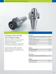
LAT <strong>and</strong> EAT facing heads are included in the st<strong>and</strong>ard<br />
program.<br />
<strong>MAPAL</strong> Technology<br />
<strong>MAPAL</strong> TOOLTRONIC® electronically controlled tools with a<br />
high level of function <strong>and</strong> flexibility are the latest development.<br />
General observations on <strong>MAPAL</strong> facing heads<br />
<strong>Facing</strong> heads are primarily used for facing, grooving <strong>and</strong> NC<br />
contour machining in large batch production on special<br />
machines.<br />
These slide tools, i.e. the toolholder <strong>and</strong> the inserts, are<br />
actuated by means of an NC controlled cross feed device.<br />
This device is located on the spindle drive unit or on the<br />
rear side of the feed unit <strong>and</strong> works centrally through the<br />
machine spindle.<br />
The economic high performance cutting operations call for<br />
a type of facing head specifically suited for each machining<br />
task or for a specially designed actuating tool.<br />
For machining cast iron <strong>and</strong> steel the LAT series is mainly<br />
used, while the EAT series is used for non-ferrous metals<br />
(aluminium).<br />
<strong>MAPAL</strong> offers 2 st<strong>and</strong>ard series of facing heads:<br />
1. The LAT series:<br />
<strong>Facing</strong> heads with linear slide actuation for large strokes in<br />
the medium spindle speed range.<br />
2. The EAT series:<br />
<strong>Actuating</strong> heads with eccentric round slide actuation for<br />
small strokes in the high spindle speed range.<br />
7
<strong>MAPAL</strong> actuating tools<br />
Function principle 1<br />
<strong>Actuating</strong> with draw bars<br />
Slide<br />
- Mainly used on special machines<br />
which are not, or only seldom,<br />
refitted.<br />
F<br />
- Slide generating by means of an<br />
actuating bar, either drawing or<br />
pushing.<br />
- Generating the actuating bar by<br />
means of an hydraulic or NC feed<br />
unit.<br />
Draw bar<br />
8
<strong>MAPAL</strong> actuating tools<br />
Function principle 2<br />
<strong>Actuating</strong> with contact stop<br />
Resetting by spring force<br />
Workpiece<br />
- Slide generating is achieved by<br />
using the workpiece surface or a<br />
special device as a contact stop.<br />
F<br />
- Special generating tools can<br />
mainly be used on machining<br />
centers with torque support.<br />
Rotary slide<br />
<strong>Actuating</strong> bar fixed<br />
by life center<br />
<strong>Actuating</strong> principles<br />
9
<strong>MAPAL</strong> actuating tools<br />
Function principle 3<br />
<strong>Actuating</strong> with coolant pressure<br />
Membrane<br />
Oil<br />
Slide<br />
Slide<br />
Coolant pressure<br />
Pressure valve<br />
Draw bar<br />
- Tool feed can be set manually by<br />
means of a throttle valve.<br />
- Slide actuation is achieved by applying<br />
the existing coolant pressure.<br />
Normally coolant at 50 bar is<br />
required.<br />
- <strong>Actuating</strong> tools can be used on<br />
machining centers with the appropriate<br />
level of coolant pressure.<br />
- Coolant controlled tools are subject<br />
to very low maintenance as<br />
the coolant pressure is not applied<br />
directly on the moving parts but<br />
via a membrane onto an oil pad<br />
which then lubricates the moving<br />
parts.<br />
- Advantage:<br />
A st<strong>and</strong>ard machine can be used<br />
without special adjustment.<br />
10
<strong>MAPAL</strong> actuating tools<br />
Function principle 4<br />
<strong>Actuating</strong> with centrifugal force<br />
F Z<br />
Pistons<br />
Axial slide<br />
- Slide actuation is achieved by using<br />
the centrifugal force produced by<br />
two symmetrically aligned pistons<br />
when the tool is rotated. The tool is<br />
automatically deactivated by spring<br />
force after the spindle slows down.<br />
Oil<br />
F Z<br />
F<br />
- Special slide generating tools driven<br />
by centrifugal force can be used on<br />
machining centers with appropriately<br />
high spindle speeds.<br />
- Advantage:<br />
St<strong>and</strong>ard machining center can be<br />
used without special adjustment.<br />
<strong>Actuating</strong> principles<br />
11
<strong>MAPAL</strong> actuating tools<br />
Function principle 5<br />
<strong>Actuating</strong> with TOOLTRONIC®<br />
Motor<br />
- Generating the slide is achieved by<br />
means of a servomotor in the tool.<br />
TOOLTRONIC® actuating tools can<br />
be used on machining centers or<br />
special machines. Machining complex<br />
contours is also possible on a<br />
machining center.<br />
Stator<br />
Transmission<br />
system<br />
- Advantage:<br />
TOOLTRONIC® provides an additional<br />
axis for a machine.<br />
Electronics<br />
TOOLTRONIC® – The driving<br />
force in precision machining<br />
<strong>MAPAL</strong> TOOLTRONIC® has been developed<br />
as a self-contained drive system. By<br />
inductive <strong>and</strong> bi-directional data transmission,<br />
TOOLTRONIC® provides a full,<br />
additional NC-axis which is incorporated<br />
into the machine control system. This<br />
means that the functions of modern CNC<br />
control systems, such as interpolation of<br />
different axes <strong>and</strong> adjustment for wear<br />
<strong>and</strong> blade radius, can also be fully utilised<br />
when TOOLTRONIC® is incorporated.<br />
The new, fully-developed electronic system<br />
sets new st<strong>and</strong>ards in the inductively<br />
transferred power of mechatronic tools.<br />
Bi-directional data transmission also<br />
allows any sensor data to be transferred<br />
from TOOLTRONIC® to the machine control,<br />
opening up new opportunities in<br />
machining <strong>and</strong> control concepts.<br />
The type of block tool to be used with<br />
TOOLTRONIC® depends on the actual<br />
machining task. In principle all selfgenerating<br />
tools from <strong>MAPAL</strong> ISOTOOL,<br />
which are activated by coolant pressure,<br />
centrifugal force, contact stop or draw<br />
bar, can be driven <strong>and</strong> controlled by<br />
TOOLTRONIC® as an alternative.<br />
However, possible applications are not<br />
just limited to cutting with a geometrically<br />
aligned blade. Combined with<br />
TOOLTRONIC®, a honing tool with selfgenerating<br />
honing pads to provide compensation<br />
for wear <strong>and</strong> dimensional<br />
adjustment becomes a block tool.<br />
12
Boring head with blade<br />
adjustment for cylinder<br />
bores<br />
Honing tool with selfgenerating<br />
honing pads<br />
for cylinder bores<br />
<strong>Actuating</strong> principles<br />
Valve guide reaming <strong>and</strong><br />
valve seat turning with<br />
EAT head<br />
LAT face slide tool with<br />
large radial stroke<br />
EAT head with boring<br />
<strong>and</strong> facing tool for<br />
turning contours<br />
Contour machining with<br />
<strong>MAPAL</strong> TOOLTRONIC®<br />
13
<strong>MAPAL</strong> actuating tools<br />
Actuated by Draw bar<br />
Slide boring bar for machining crankshaft bearing holes <strong>and</strong> thrust walls<br />
201.5<br />
120<br />
HSK 40<br />
ø32<br />
ø144<br />
ø8 H7<br />
90<br />
Description :<br />
Tool for roughing <strong>and</strong> finishing of<br />
crankshaft journals <strong>and</strong> – with<br />
actuating element – for facing the<br />
thrust walls.<br />
Machining values:<br />
vc = 120 m/min<br />
n = 420 1/min<br />
f = 0,16 mm/U<br />
Internal machining with EAT facing head on special machines<br />
HUB 20<br />
14<br />
Description:<br />
Machining various diameters<br />
8 – 13.5 mm in IT7 quality including<br />
machining recesses<br />
Machining values:<br />
vc<br />
= 250...425 m/min<br />
n = 10000 min -1<br />
f cylindrical turning = 0.1 mm/rev<br />
f recessing = 0.1 mm/rev<br />
Material: Gd-AlSi12 (Cu)
<strong>MAPAL</strong> actuating tools<br />
Actuated by Draw bar<br />
Optional for 4 <strong>and</strong> 6 engine blocks<br />
1530<br />
Material: Ci26 CuCr e SCI 60<br />
<strong>Actuating</strong> tools<br />
in practice<br />
Line boring bar for cylinder bore<br />
745<br />
ø60<br />
ø232<br />
Description:<br />
Semi-finishing <strong>and</strong> finishing including<br />
all recesses <strong>and</strong> water jacket control<br />
cuts for truck crankcases.<br />
Feature:<br />
Nine machining steps combined on one<br />
work station.<br />
Material: CG26Cr<br />
15
<strong>MAPAL</strong> actuating tools<br />
Actuated by Draw bar<br />
Boring bar with automatic cutting edge adjustment for wear compensation<br />
212<br />
ø176<br />
ø83<br />
Description:<br />
Finish machining of cylinder bores for<br />
honing.<br />
4 inserts for semi-finishing;<br />
2 adjustable inserts for finishing.<br />
Machining values:<br />
vc = 120 m/min<br />
n = 460 min -1<br />
f = 0.15 mm/rev<br />
Material: CGI<br />
Angular turning head for valve seat <strong>and</strong> valve guide<br />
125<br />
16<br />
Description:<br />
Turning of the main <strong>and</strong> secondary<br />
chamfers of a valve seat. Reaming of<br />
the valve passages. Sleeve movement<br />
does not depend on the feed movement<br />
of the basic tool.<br />
Machining values:<br />
Valve seat<br />
Valve guide<br />
vc = 206 m/min vc = 57 m/min<br />
n = 2000 min -1 n = 3000 min -1<br />
f = 0.03 mm/rev f = 0.1 mm/rev<br />
Material: Misc. sintered metals
75°<br />
<strong>MAPAL</strong> actuating tools<br />
Actuated by contact stop<br />
Special actuating tool with contact stop for facing <strong>and</strong> recessing<br />
235 ± 0.01<br />
EM 71.23<br />
314<br />
200<br />
178<br />
ø29<br />
ø120<br />
ø29<br />
ø120<br />
ø128.31<br />
EM#2 ø123<br />
EM#1<br />
300<br />
Description:<br />
Machining of the balcony depth <strong>and</strong><br />
the recess on a cylinder bore for a<br />
motor. Simultaneous machining of<br />
end face <strong>and</strong> recess acc. to DIN 509 –<br />
Form F.<br />
Machining values:<br />
vc = 120 m/min<br />
n = 300 min -1<br />
f = 0.08 mm/rev<br />
Material: cast iron CG25<br />
<strong>Actuating</strong> tools<br />
in practice<br />
Special generating tool for spherical machining<br />
22<br />
Hub<br />
Description:<br />
Machining the spherical form in<br />
differential housings by contacting<br />
a life center bearing. Slide is reset<br />
by spring force.<br />
Machining values:<br />
vc = 130 m/min<br />
n = 410...1300 min -1<br />
f = 0.05 mm/rev<br />
Material: SCI 40<br />
17
<strong>MAPAL</strong> actuating tools<br />
Actuated by coolant pressure<br />
Line boring bar for machining crankshaft bearing holes on machining centers<br />
725<br />
ø69 H7<br />
ø70<br />
Description:<br />
Tool for simultaneous machining<br />
of journals on machining centers.<br />
Guiding by means of carbide or<br />
PCD pads which can be actuated.<br />
Machining values:<br />
vc = 44 m/min<br />
n = 200 min -1<br />
f = 0.08 mm/rev<br />
Material: SCI 75<br />
Line boring bar for machining thrust bearings on machining centers<br />
364<br />
18<br />
Description:<br />
Average machining values:<br />
Tool for the facing of thrust bearings vc = 95 m/min<br />
of cylindrical crankcases on machining n = 320 min -1<br />
centers.<br />
Supported in the workpiece by carbide<br />
f cylindrical turning = 0.15 mm/rev<br />
or PCD pads. Material: SCI 75
<strong>MAPAL</strong> actuating tools<br />
Actuated by centrifugal force<br />
Centrifugal force tool (CFT) for taper machining<br />
333.42<br />
230<br />
76 45.5<br />
31 Hub<br />
Taper 1:6<br />
9.527283°<br />
ø20<br />
+ 0.084<br />
27.3 ± 0.1<br />
Description:<br />
Angular slide tool for finishing the<br />
taper bore on a passenger car journal.<br />
Machining is starting from the small<br />
diameter of the bore.<br />
Machining values:<br />
vc = 230 m/min<br />
n = 3500 min -1<br />
f = 0.08 mm/rev<br />
Material: SCI 40<br />
<strong>Actuating</strong> tools<br />
in practice<br />
Boring bar with elements controlled by centrifugal force for sleeve generating<br />
218<br />
270<br />
Start position<br />
Plunge cutting valve seat<br />
(up to 3 chamfers)<br />
End position<br />
Machining valve guide<br />
D = 4...9mm<br />
52 Hub 52 Hub<br />
ø125<br />
Gas<br />
spring<br />
Gas<br />
spring<br />
ø125<br />
Description:<br />
Precision machining of valve seat <strong>and</strong><br />
valve guide on a cylinder head.<br />
After plunge cutting the valve seat,<br />
the sleeve is generated with the reamer<br />
Machining values:<br />
Valve seat<br />
Valve guide<br />
vc = 120 m/min vc = 120 m/min<br />
n = 1.000-3.000 U/min n = 3.500-6.000 U/min<br />
f = 0,05 m/min f = 0,15 m/min<br />
Material:<br />
Misc. sintered metals<br />
19
<strong>MAPAL</strong><br />
inserts<br />
Inserts with special geometries for<br />
producing recesses <strong>and</strong> contours<br />
Maximum efficiency <strong>and</strong> economy from the <strong>MAPAL</strong><br />
actuating tools is primarily achieved by using the right<br />
insert.<br />
<strong>MAPAL</strong> offers an extensive range of st<strong>and</strong>ard <strong>and</strong> special<br />
inserts covering all the requirements for a variety<br />
of cutting materials, coatings <strong>and</strong> appropriate insert<br />
geometries <strong>and</strong> accuracies.<br />
Indexable inserts<br />
with PCD or CBN blanks<br />
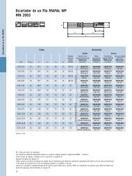
Inserts for tools with guide pads for the<br />
precision machining of bores (WP <strong>and</strong> HX)<br />
ISO inserts in all versions <strong>and</strong> in the high precision<br />
<strong>MAPAL</strong> tolerance grade X<br />
Special inserts with multiple cutting edges for<br />
recessing operations<br />
20
<strong>MAPAL</strong><br />
facing heads<br />
St<strong>and</strong>ard<br />
facing heads<br />
21
<strong>MAPAL</strong> st<strong>and</strong>ard<br />
facing heads<br />
LAT...1...<br />
Single slide<br />
Spindle speed range:<br />
low spindle speeds<br />
LAT…1…spindle speed limit:<br />
n max =<br />
2400<br />
Hub *<br />
* slide stroke <strong>and</strong> change of center of gravity<br />
Type of operation:<br />
Mainly internal machining, medium to<br />
heavy machining with maximum overall<br />
rigidity in the “slide – tool” system.<br />
LAT...2...<br />
Parallel twin slide<br />
Spindle speed range:<br />
Medium spindle speeds.<br />
Important note: The traction force<br />
depends on spindle speed, stroke <strong>and</strong><br />
tool weight.<br />
<strong>MAPAL</strong> ISOTOOL supplies calculations<br />
for the dimensions of the cross feed<br />
device.<br />
Type of operation:<br />
In contrast to the st<strong>and</strong>ard “face turning<br />
from outside to inside”, LAT…2…<br />
facing heads can also be supplied in a<br />
semi-st<strong>and</strong>ard version for “face turning<br />
from inside to outside”.<br />
22
<strong>MAPAL</strong> st<strong>and</strong>ard<br />
facing heads<br />
LAT...C...<br />
Single slide with counter balance<br />
Spindle speed range:<br />
Medium spindle speeds<br />
Important note: Traction depends on<br />
spindle speed, stroke <strong>and</strong> tool weight.<br />
<strong>MAPAL</strong> ISOTOOL supplies calculations<br />
for the dimensions of the cross feed<br />
device.<br />
Type of operation:<br />
With the LAT…C… series the block tools<br />
are designed for a specific weight <strong>and</strong><br />
aligned on the covered counter-balance<br />
slide.<br />
EAT...<br />
Rotary slide<br />
ST<strong>and</strong>ard<br />
facing heads<br />
Spindle speed range:<br />
high to maximum spindle speeds<br />
Advantage: Very low machining forces<br />
on draw bar.<br />
23
<strong>MAPAL</strong> st<strong>and</strong>ard<br />
facing heads<br />
Machining tasks:<br />
Boring<br />
Face turning<br />
Boring<br />
Grooving<br />
Boring with cutting edge lifting<br />
Boring, facing,<br />
grooving (internal)<br />
Contour turning,<br />
grooving (external)<br />
<strong>Facing</strong><br />
Contour turning (internal)<br />
Grooving (external),<br />
centering function optional<br />
24
<strong>MAPAL</strong> st<strong>and</strong>ard<br />
facing heads<br />
The LAT facing heads<br />
Here the translatory draw bar movement<br />
of the cross feed device is redirected<br />
by the mechanical slide drive elements<br />
into radial or angular actuating<br />
movements.<br />
The application data – in particular the<br />
cutting speed – resulting from the<br />
machining task, provide appropriate<br />
dynamics at high spindle speeds. As the<br />
traction depends on the spindle speed<br />
<strong>and</strong> the stroke, the performance of the<br />
cross feed device must be suitably<br />
dimensioned. <strong>MAPAL</strong> ISOTOOL provides<br />
the appropriate support <strong>and</strong> the necessary<br />
calculations.<br />
The EAT actuating heads<br />
In conjunction with the relevant<br />
mechanical elements, the translatory<br />
draw bar movement of the cross feed<br />
device is redirected in the EAT actuating<br />
head by a cam control system into a<br />
rotary movement <strong>and</strong> produces the necessary<br />
swing motion by means of the<br />
excentrically supported rotary slide.<br />
Compared to the LAT system, EAT actuating<br />
heads require significantly less<br />
activating forces <strong>and</strong> drive power in a<br />
stable, dynamically balanced situation<br />
<strong>and</strong> are, therefore, particularly suited<br />
for HSC machining.<br />
ST<strong>and</strong>ard<br />
facing heads<br />
25
Single slide facing head<br />
LAT...1...<br />
LAT-xxx-1-yy<br />
H<br />
L1<br />
L2<br />
C<br />
L4<br />
L3<br />
Z max<br />
A<br />
beta<br />
alpha<br />
D<br />
Q max<br />
d5<br />
d1<br />
d2<br />
d3<br />
d4<br />
L6<br />
L5<br />
Q max<br />
G1<br />
E<br />
40°<br />
D1<br />
1<br />
T 1<br />
Z max<br />
B<br />
Reference code: LAT-xxx-1-yy<br />
LAT<br />
Linear <strong>Actuating</strong> Tool<br />
(facing head)<br />
xxx<br />
head diameter = D<br />
1 with one (1) linear slide<br />
yy<br />
cross stroke = Qmax<br />
26
Single slide facing head<br />
LAT...1...<br />
Reference codes<br />
LAT-080-1-10 LAT-100-1-17 LAT-125-1-22 LAT-160-1-32 LAT-200-1-40 LAT-250-1-50 LAT-320-1-63<br />
Main<br />
dimensions<br />
D<br />
Q max<br />
Z max<br />
H<br />
80 100 125 160 200 250 320<br />
10 17 22 32 40 50 63<br />
11,92 20,26 26,22 38,14 47,67 59,59 75,08<br />
42 48 58 70 85 100 125<br />
Connection dimensions<br />
D1<br />
d 1<br />
d H7 2<br />
d 3<br />
d 4<br />
d 5 j5<br />
L 1<br />
L 2<br />
L 3<br />
L 4<br />
L 5<br />
L 6<br />
G 1<br />
T 1<br />
alpha<br />
beta<br />
gamma<br />
66,7 89 114 149 186 232 300<br />
M10x1 L.H. M10x1 L.H. M12x1,5 L.H. M16x1,5 L.H. M16x1,5 L.H. M20x1,5 L.H. M20x1,5 L.H.<br />
12 12 14 18 18 25 25<br />
16 16 18 25 32 40 40<br />
29,5 29,5 31,5 39,5 55,5 69,5 69,5<br />
30 30 32 40 56 70 70<br />
46 62 73 93 125 153 168<br />
31,08 38,74 43,78 50,86 72,33 88,41 87,92<br />
6 8 10 10 10 20 30<br />
3 3 3 4 5 5 5<br />
8 12 12 12 12 15 15<br />
14 18 18 24 32 40 40<br />
M6 (3x) M6 (4x) M6 (6x) M6 (8x) M8 (8x) M10 (8x) M12 (8x)<br />
7,5 14 14,8 13 15 21 29<br />
- - - 15° 15° 15° 15°<br />
- 35° 35° 45° 45° 45° 50°<br />
3 x 120° - - - - - -<br />
Slide<br />
dimensions<br />
A<br />
B<br />
C<br />
E<br />
70 83 103 128 160 200 257<br />
36 40 56 70 90 110 130<br />
12 12 14 17 19 24 28<br />
28 35 42 60 76 94 107<br />
ST<strong>and</strong>ard<br />
facing heads<br />
27
Parallel double slide facing head<br />
LAT...2...<br />
LAT-xxx-2-yy<br />
H<br />
L1<br />
L2<br />
D1<br />
L4<br />
beta 1<br />
L3<br />
Z max<br />
D<br />
Q max<br />
d5<br />
d1<br />
d2<br />
d3<br />
d4<br />
L6<br />
L5<br />
Q max<br />
G1<br />
A1<br />
alpha 1<br />
40°<br />
1<br />
T 1<br />
Z max<br />
B1<br />
B2<br />
Reference code: LAT-xxx-2-yy<br />
LAT<br />
Linear <strong>Actuating</strong> Tool<br />
(facing head)<br />
xxx<br />
head diameter = D<br />
2 with 2 opposite linear<br />
slide<br />
yy<br />
cross stroke = Qmax<br />
28
Parallel double slide facing head<br />
LAT...2...<br />
Reference codes<br />
LAT-100-2-17 LAT-125-2-22 LAT-160-2-32 LAT-200-2-40 LAT-250-2-50 LAT-320-2-63<br />
Main<br />
Connection dimensions<br />
dimensions<br />
Slide<br />
dimensions<br />
D<br />
Q max<br />
Z max<br />
H<br />
D1<br />
d 1<br />
d H7 2<br />
d 3<br />
d 4<br />
d 5 j5<br />
L 1<br />
L 2<br />
L 3<br />
L 4<br />
L 5<br />
L 6<br />
G 1<br />
T 1<br />
alpha<br />
beta<br />
A 1<br />
B 1<br />
B 2<br />
100 125 160 200 250 320<br />
17 22 32 40 50 63<br />
20,26 26,22 38,14 47,67 59,59 75,08<br />
48 58 70 85 100 125<br />
89 114 149 186 232 300<br />
M10x1 L.H. M12x1,5 L.H. M16x1,5 L.H. M16x1,5 L.H. M20x1,5 L.H. M20x1,5 L.H.<br />
12 14 18 18 25 25<br />
16 18 25 32 40 40<br />
29,5 31,5 39,5 55,5 69,5 69,5<br />
30 32 40 56 70 70<br />
62 73 93 125 153 168<br />
38,74 43,78 50,86 72,33 88,41 87,92<br />
8 10 10 10 20 30<br />
3 3 4 5 5 5<br />
12 12 12 12 15 15<br />
18 18 24 32 40 40<br />
M6 (4x) M6 (6x) M6 (8x) M8 (8x) M10 (8x) M12 (8x)<br />
14 14,8 13 15 21 29<br />
- 0° 15° 15° 15° 15°<br />
35° 35° 45° 45° 45° 50°<br />
83 103 128 158 200 257<br />
53 68 80 102 115 145<br />
19 24 28 36 40 52,5<br />
ST<strong>and</strong>ard<br />
facing heads<br />
29
Single slide facing head LAT...C...<br />
with covered counter balance slide<br />
LAT-xxx-C-yy<br />
H<br />
L1<br />
L2<br />
C<br />
L4<br />
L3<br />
Z max<br />
beta<br />
alpha<br />
D<br />
Q max<br />
d5<br />
d1<br />
d2<br />
d3<br />
d4<br />
L6<br />
L5<br />
G1<br />
A<br />
E<br />
40°<br />
1<br />
T 1<br />
Q max<br />
B<br />
Z max<br />
D1<br />
Reference code: LAT-xxx-C-yy<br />
LAT<br />
Linear <strong>Actuating</strong> Tool<br />
(facing head)<br />
xxx<br />
head diameter = D<br />
C<br />
with one (1) slide<br />
<strong>and</strong> one (1) covered<br />
counter slide<br />
yy<br />
cross stroke = Qmax<br />
30
Single slide facing head LAT...C...<br />
with covered counter balance slide<br />
Reference codes<br />
LAT-100-C-12 LAT-125-C-16 LAT-160-C-24 LAT-200-C-32 LAT-250-C-40<br />
Main<br />
dimensions<br />
D<br />
Q max<br />
Z max<br />
H<br />
100 125 160 200 250<br />
12 16 24 32 40<br />
14,3 19,07 28,6 38,14 47,67<br />
74 92 105 123 145<br />
D1<br />
d 1<br />
d H7 2<br />
d 3<br />
d 4<br />
d 5 j5<br />
L 1<br />
L 2<br />
L 3<br />
L 4<br />
L 5<br />
L 6<br />
G 1<br />
T 1<br />
alpha<br />
beta<br />
89 114 149 186 232<br />
M10x1 L.H. M12x1,5 L.H. M16x1,5 L.H. M16x1,5 L.H. M20x1,5 L.H.<br />
12 14 18 18 25<br />
16 18 25 32 40<br />
29,5 31,5 39,5 55,5 69,5<br />
30 32 40 56 70<br />
56 73 93 125 141<br />
38,7 50,93 60,4 81,86 88,33<br />
8 10 20 10 20<br />
3 3 4 5 5<br />
12 12 12 12 15<br />
18 18 24 24 40<br />
M6 (4x) M6 (6x) M6 (8x) M8 (8x) M10 (8x)<br />
12 14 12,5 17 17<br />
- 0° 15° 15° 15°<br />
35° 35° 45° 45° 45°<br />
Slide<br />
dimensions<br />
A<br />
B<br />
C<br />
E<br />
88 109 136 168 210<br />
40 56 70 90 110<br />
14 14 19 22 24<br />
30 36 52 66 90<br />
ST<strong>and</strong>ard<br />
facing heads<br />
31
NSB<br />
Rotary slide facing head EAT...<br />
with eccentric actuation<br />
EAT-xxx-yyy-HSK-Czz<br />
Wrench accesss –<br />
high HSK drive key<br />
BH<br />
SL<br />
KH<br />
BL<br />
LH<br />
Drive key (shown out<br />
of position)<br />
HSK<br />
Interfering contour – counterweight<br />
L3<br />
ZL<br />
G3<br />
TK1<br />
30°<br />
NSA NSA<br />
0° bis 36°<br />
QH<br />
Cutting edge end<br />
position, bar drawn<br />
KD<br />
AD<br />
E<br />
L2<br />
L1<br />
ZD<br />
BD<br />
G2<br />
D1<br />
SD<br />
MBA<br />
SW<br />
NSL<br />
Counterweight to block tool<br />
7<br />
End position,<br />
bar pushed<br />
MBD<br />
EAT heads in special designs<br />
available on request<br />
Dimensions for small EAT 100 are<br />
designed without internal coolant<br />
system<br />
Reference code example:<br />
EAT-100-050-HSK-C40<br />
EAT Eccentric <strong>Actuating</strong> Tool<br />
100 head diameter = D<br />
050 Eccentricity = E<br />
(here E = 5.0 mm)<br />
HSK-C40 Tool holder<br />
32
Rotary slide facing head EAT...<br />
with eccentric actuation<br />
Reference codes<br />
EAT-085-032-HSK-C32 EAT-100-050-HSK-C40 EAT-125-080-HSK-C50 EAT-160-125-HSK-C63 EAT-200-200-HSK-C80 EAT-280-320-HSK-C80<br />
Main<br />
dimensions<br />
AD<br />
KD<br />
KH<br />
BH<br />
E<br />
QH<br />
55 60 70 90 110 110<br />
85 100 125 160 200 280<br />
85 98 111 129 149 177<br />
95 113 131 154 180 203<br />
3,2 5,0 8,0 12,5 20,0 32,0<br />
3,7 5,9 9,4 14,7 23,5 37,6<br />
Connection dimensions<br />
Bushing <strong>and</strong> bar dimensions<br />
with thread<br />
LH<br />
BD<br />
BL<br />
SD<br />
SL<br />
D1<br />
L1<br />
G2<br />
L2<br />
22,4 28,8 36,0 44,8 56,8 72,0<br />
28,8 32,4 39,6 50,4 63,0 81,0<br />
69 83 98 118 145 178<br />
16 18 22 28 35 45<br />
97 118 140 168 208 256<br />
11 13 16 20 22 25<br />
12,5 13,8 16 19 20,5 22,8<br />
10x1 12x1,5 14x1,5 18x1,5 20x1,5 22x1,5<br />
12,5 15 17,5 22,5 25 27,5<br />
Connection dimensions,<br />
spindle dimensions<br />
ZD<br />
ZL<br />
TK1<br />
G3<br />
L3<br />
MBD<br />
MBA<br />
30 35 45 60 80 100<br />
10 14 19 25 35 50<br />
74 88 110 145 182 260<br />
M5 M6 M8 M8 M10 M12<br />
7,5 9 12 12 15 15<br />
9 14,7 14,7 16,6 16,6 24<br />
35 40 52 68 88 100<br />
Slide<br />
dimensions<br />
NSB<br />
NSA<br />
NSL<br />
SW<br />
HSK<br />
6 8 10 12 16 16<br />
16 20,5 25,5 32 40,5 50<br />
4 4 5 6 8 8<br />
72 72 72 72 72 72<br />
C32 C40 C50 C63 C80 C80<br />
ST<strong>and</strong>ard<br />
facing heads<br />
33
Adjustments to customer requirements<br />
Tooth angle / translation ratio<br />
Radial stroke,<br />
slide<br />
Tooth angle<br />
Axial stroke,<br />
draw bar<br />
Depending on the machining task <strong>and</strong><br />
the machine requirements, the following<br />
variations can be supplied as semist<strong>and</strong>ards<br />
without additional charge.<br />
40° – tooth angle – st<strong>and</strong>ard<br />
45° – tooth angle 1:1<br />
38° – tooth angle 1:1.2<br />
26.565° – tooth angle 1:2<br />
Draw bar designed with bayonet coupling <strong>and</strong> stop<br />
Drawbar designed with stop<br />
L8<br />
L8<br />
S<br />
L7<br />
L2 Zmax V L9<br />
R<br />
L7<br />
L2<br />
Zmax<br />
V<br />
L9<br />
d6<br />
d6<br />
d9<br />
d7<br />
d4<br />
d8<br />
d7<br />
d4<br />
Reference codes<br />
Special design<br />
d6 d7 d8 d9 L7 L8 L9 V S R h6<br />
34<br />
LAT-080-1-10<br />
LAT-100-1-17<br />
LAT-125-1-22<br />
LAT-160-1-32<br />
LAT-200-1-40<br />
LAT-250-1-50<br />
LAT-320-1-63<br />
LAT-100-2-17<br />
LAT-125-2-22<br />
LAT-160-2-32<br />
LAT-200-2-40<br />
LAT-250-2-50<br />
LAT-320-2-63<br />
LAT-100-C-12<br />
LAT-125-C-16<br />
LAT-160-C-24<br />
LAT-200-C-32<br />
LAT-250-C-40<br />
M24x1,5 19 13 17 8 74 11 17 8,2 6<br />
M24x1,5 19 13 17 12 90 11 17 8,2 6<br />
M27x1,5 19 15 17 18 105 13 19 8,2 6<br />
M33x1,5 26 19 21 20,5 133 13 27 10,2 10<br />
M45x1,5 33 19 26 32,5 172 15 32 12,2 10<br />
M56x1,5 41 26 33 38 210 19 38 15,2 12<br />
M56x1,5 41 26 33 36 225 19 38 15,2 12<br />
M24x1,5 19 13 17 12 90 11 17 8,2 6<br />
M27x1,5 19 15 17 18 105 13 19 8,2 6<br />
M33x1,5 26 19 21 20,5 133 13 27 10,2 10<br />
M45x1,5 33 19 26 32,5 172 15 32 12,2 10<br />
M56x1,5 41 26 33 38 210 19 38 15,2 12<br />
M56x1,5 41 26 33 36 225 19 38 15,2 12<br />
M24x1,5 19 13 17 12 84 11 17 8,2 6<br />
M27x1,5 19 15 17 18 105 13 19 8,2 6<br />
M33x1,5 26 19 21 30 133 13 27 10,2 10<br />
M45x1,5 33 19 26 42 172 15 32 12,2 10<br />
M56x1,5 41 26 33 38 198 19 38 15,2 12
Adjustments to customer requirements<br />
Adaptor flanges for st<strong>and</strong>ard spindle heads <strong>and</strong> for special spindles available on request<br />
B<br />
Code:<br />
D<br />
LK<br />
d<br />
B<br />
flange diameter<br />
hole circle diameter<br />
centering diameter<br />
flange thickness<br />
d<br />
LK-Ø<br />
D<br />
Tool holder design – hole pattern for tool fixing<br />
LAT...1 <strong>and</strong> LAT...C<br />
LAT...2<br />
ST<strong>and</strong>ard<br />
facing heads<br />
- flange connection<br />
- short, stable block tool<br />
- only inserts are changed<br />
-HSK<br />
- Rapid tool change<br />
- can be preset<br />
- good tool change<br />
accuracy<br />
- ABS<br />
- Rapid tool change<br />
- can be preset<br />
- flange connection<br />
- tool can also be<br />
changed rapidly<br />
35
A Review of <strong>MAPAL</strong>’s <strong>Competence</strong><br />
Reaming <strong>and</strong> Fine Boring<br />
From the wide range of single <strong>and</strong> twin-bladed reamers with guide pads, together with fine<br />
boring tools with guide pads <strong>and</strong> WP or HX blades, to the HPR High Performance Reamers<br />
combined with the <strong>MAPAL</strong> HFS® Head Fitting System for exact concentricity <strong>and</strong> accurate<br />
changeover – to give you a general view of our complete knowledge <strong>and</strong> experience in<br />
pre cision machining bores.<br />
PCD <strong>Tools</strong><br />
For pre-machining <strong>and</strong> finish machining, <strong>MAPAL</strong> also offers an extensive programme of<br />
pre cision tools with fixed PCD (polycrystalline diamond) blades. This includes precision gun<br />
boring tools plus circular <strong>and</strong> end milling tools. The programme of face milling heads from<br />
the PowerMill <strong>and</strong> EcoMill series is characterised by simple, sturdy design <strong>and</strong> rapid, accurate<br />
blade setting.<br />
ISO <strong>Tools</strong><br />
This aspect of <strong>MAPAL</strong> competence is made up of special tools with ISO elements for gun<br />
boring <strong>and</strong> milling. This includes precision ground blades in the widest variety of cutting<br />
materials <strong>and</strong> coatings. The use of <strong>MAPAL</strong>'s tried <strong>and</strong> tested adjustment system ensures that<br />
the blades are accurately matched to the task. <strong>MAPAL</strong> offers particular knowledge <strong>and</strong> ex -<br />
perience in tangential technology.<br />
<strong>Actuating</strong> Slide <strong>Tools</strong><br />
<strong>Actuating</strong> slide tools offer a high potential for rationalisation <strong>and</strong> optimisation on special<br />
machines <strong>and</strong> machining centres. In addition to the conventional facing heads, <strong>MAPAL</strong> also<br />
supplies EAT <strong>and</strong> LAT performance-enhanced actuating systems for generating slide tools.<br />
<strong>MAPAL</strong> TOOLTRONIC® tools with their extraordinary range of functions are the latest development.<br />
Drilling<br />
Yet another area is the product programme for drilling. <strong>MAPAL</strong> offers the right tool concept<br />
for every task, whether for machining aluminium, steel or cast iron, hard machining or dry<br />
machining or for use in HSC areas. Specially developed coatings <strong>and</strong> drills with PCD blades<br />
complete the broad-based drilling programme.<br />
Clamping<br />
<strong>MAPAL</strong>'s modern clamping systems, in conjunction with <strong>MAPAL</strong>'s tried <strong>and</strong> tested reaming<br />
<strong>and</strong> fine boring tools, guarantee maximum productivity <strong>and</strong> economy. Whether HSK, ISO or<br />
HFS®, these high-precision connections <strong>and</strong> interfaces provide the concentricity <strong>and</strong> changeover<br />
accuracy essential to modern production.<br />
Customer Services<br />
Project planning, maintenance, management <strong>and</strong> optimisation – the complete CTS® service<br />
package from <strong>MAPAL</strong> will accompany you from process design to permanent process optimisation<br />
<strong>and</strong> will ensure optimum <strong>and</strong> cost-saving use of your tools with the best possible<br />
results.<br />
AST-E-01-020-0308-MZ Printed in Germany/Right of technical modifications reserved.<br />
<strong>MAPAL</strong> Präzisionswerkzeuge Dr. Kress KG<br />
P.O. Box 1520 • D-73405 Aalen<br />
Phone +49 (0) 73 61 / 5 85-0 • Fax +49 (0) 73 61 / 5 85-1 50<br />
info@de.mapal.com • www.mapal.com<br />
36