CL151 GLC Compressor/Limiter/ Gate - Pro Music
CL151 GLC Compressor/Limiter/ Gate - Pro Music
CL151 GLC Compressor/Limiter/ Gate - Pro Music

Create successful ePaper yourself
Turn your PDF publications into a flip-book with our unique Google optimized e-Paper software.
The plug connected to the Tip is the "Send" which will connect to the Input of the signal<br />
processing device, and the Ring is the "Return" which connects directly to the detector<br />
(compression control) circuit.<br />
Side Chain circuits are often used in "ducking". Ducking is momentarily lowering one signal<br />
under another signal. For example, you may wish to automatically lower a music signal<br />
under a paging microphone signal, then have the music return to normal level after the<br />
page is over. This would be accomplished by running the music into the compressor, and<br />
having the page signal connect into the Side Chain return. The page signal must also be<br />
connected to the main mixer or amplifier as well. When the paging signal begins, its signal<br />
goes to the main mixer and the Side Chain circuitry. The music is compressed or "ducked"<br />
under the page.<br />
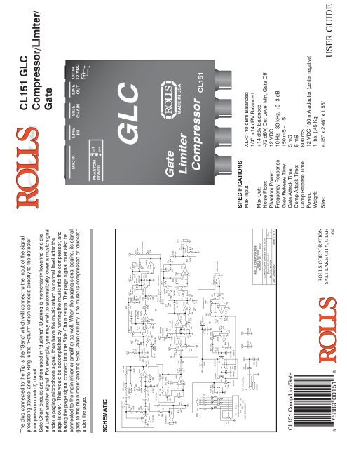
SCHEMATIC<br />
ROLLS CORPORATION<br />
SALT LAKE CITY, UTAH<br />
1/04<br />
<strong>CL151</strong> <strong>GLC</strong><br />
<strong>Compressor</strong>/<strong>Limiter</strong>/<br />
<strong>Gate</strong><br />
SPECIFICATIONS<br />
Max Input: XLR: -10 dBm Balanced<br />
1/4": +14 dBV Balanced<br />
Max Out: +14 dBV Balanced<br />
Noise Floor: -72 dBV, Out Level Min, <strong>Gate</strong> Off<br />
Phantom Power: 12 VDC<br />
Frequency Response: 10 Hz - 30 kHz, +0 -3 dB<br />
<strong>Gate</strong> Release Time: 150 mS - 1 S<br />
<strong>Gate</strong> Attack Time: 5 mS<br />
Comp Attack Time: 5 mS<br />
Comp Release Time: 800 mS<br />
Power: 12 VDC 150 mA adapter (center negative)<br />
Weight: 1 lbs. (.45 Kg)<br />
Size: 4.15" x 2.46" x 1.55"<br />
USER GUIDE
INTRODUCTION<br />
Thank you for your purchase of the <strong>CL151</strong> <strong>GLC</strong> <strong>Gate</strong> <strong>Compressor</strong> <strong>Limiter</strong>. This unit provides<br />
smooth, soft-knee compression and limiting with a gate. Gain reduction is indicated<br />
via a front panel 5-segment LED bargraph. Plus, the unit has a mic preamp input with 12<br />
volts phantom power available.<br />
WARRANTY INFO<br />
Please visit our website, www.rolls.com, for the Rolls 1 Year Warranty information and<br />
registration.<br />
FRONT PANEL<br />
INPUT: Adjusts the amount of input signal to the <strong>CL151</strong>, from no signal to +20 dB.<br />
GATE REL: This control adjusts the amount of time taken for the gate circuitry to "close" or<br />
mute the output, after the signal level has dropped below the gate Threshold level.<br />
THRESH: Sets the point at which the input signal must surpass to "open" the gate circuitry<br />
or allow signal to pass to the output.<br />
GATE LED: When lit, indicates that the gate is "closed" or the output is muted.<br />
COMP RATIO: This control sets the signal to compression ratio. This ratio relates to the<br />
amount of increase of input compared to output signal. Thus, at a 1:1 ratio, a 1 dB increase<br />
of input signal will result in a 1 dB increase of output signal. At 2:1, a 2 dB increase<br />
of input signal will result in only 1 dB increase of output signal. At 8:1, an 8 dB increase of<br />
input signal will result in a 1dB increase of output signal.<br />
THRESH: Sets the point that the input signal must reach for compression to begin.<br />
GAIN REDUCTION LEDs: This LED ladder indicates the amount of signal compression,<br />
or gain reduction.<br />
OUTPUT: Adjusts the amount of overall output signal from the <strong>CL151</strong>.<br />
PWR: Indicates that the <strong>CL151</strong> is connected to the power source, and the unit is on.<br />
REAR PANEL<br />
MIC IN: Balanced XLR jack, for connection to any standard dynamic or condenser microphone.<br />
LINE IN: Balanced 1/4" TRS jack for connection to balanced or unbalanced line level<br />
signals.<br />
SIDE CHAIN: 1/4" TRS jack for connection via TRS insert cable to a device such as an<br />
equalizer or other device, for direct access to the <strong>CL151</strong> detector circuitry.<br />
LINE OUT: Balanced 1/4" TRS jack for connection to a mixer's line input or to an amplifier.<br />
DC IN: For connection to the Rolls PS27 12 VDC, 150 mA power supply; outside of the<br />
barrel is positive.<br />
SIDE PANEL<br />
PHANTOM POWER: Jumper header for connecting 12 VDC phantom power to the XLR<br />
Mic Input. Phantom power is engaged by carefully removing the jumper, and reconnecting<br />
it to the pins toward the <strong>CL151</strong> controls.<br />
CONNECTION AND OPERATION<br />
The example below shows the connection of a microphone. If the microphone requires<br />
phantom power, make sure the Phantom Power jumper is connecting the two pins closest<br />
to the front panel. Connect the output of the <strong>CL151</strong> via a balanced or unbalanced 1/4"<br />
plug to the input of a mixer or amplifier.<br />
Begin adjustments by setting the INPUT and OUTPUT levels at O (about 10 O'clock). This<br />
setting is for "unity gain".<br />
Set the gate THRESH for "off", the COMP RATIO for 1:1, and the compressor THRESH<br />
for +10. These initial settings essentially bypass the gate and compressor circuits.<br />
The compressor RATIO and THRESH controls work together to control the amount of<br />
compression, and the point at which compression begins respectively. Decreasing the<br />
THRESH control lowers the amount of signal required to begin compression - so it compresses<br />
sooner. This works with the RATIO control which, when increased, increases the<br />
amount of compression.<br />
The gate THRESH control, after being turned slightly counterclockwise from the "off" position,<br />
goes to its maximum level. This means it requires a higher signal level to "open" the<br />
gate. As the gate THRESH control is turned counterclockwise, a lower and lower signal is<br />
required to open the gate.<br />
The gate REL (release time) control sets the amount of time taken for the gate to "close"<br />
after the signal drops below the THRESH level. For example, the <strong>CL151</strong> will continue<br />
passing a sustaining note until the level drops below the THRESH level, and the REL time<br />
has passed.<br />
Connection Example<br />
(Explanation continues on the next page)<br />
USING THE SIDE CHAIN<br />
To access the compressor detector<br />
circuit directly, Rolls has included<br />
a Side Chain jack. The Side Chain<br />
works somewhat like an effects<br />
loop, with a send and return point. A<br />
1/4" Tip-Ring-Sleeve "Insert Cable"<br />
is required to utilize the Side Chain.<br />
See the picture below.

![2 Use the CATEGORY [DEC] / [INC] but - Pro Music](https://img.yumpu.com/43682164/1/190x245/2-use-the-category-dec-inc-but-pro-music.jpg?quality=85)